Project 1_Comparative study of different storey buildings for Seismic forces
Aim :Project 1_Comparative study of different storey buildings for Seismic forces
Procedure : Go to ETAB model
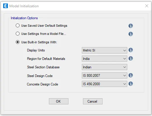
2. Select the Intiallization option
3. Select steel Design Code IS800:2007
4. Select Concrete Design Code IS 456:2000
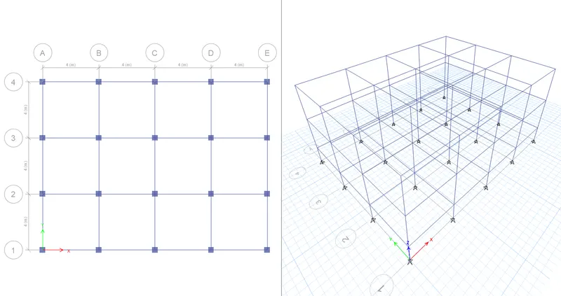
6. Select the grids with the 4M X 4M
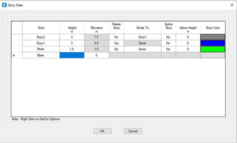
7. Select the no. of Storey
8. And then select it to similar to STOREY 1
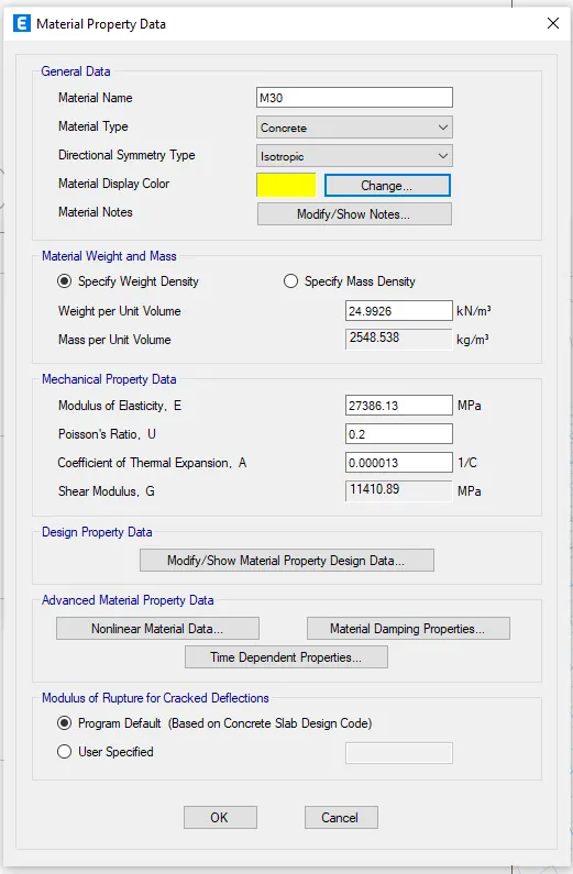
9. Select the Material Properties
10. Select the Concrete Grade as M30
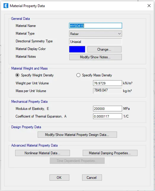
11. Select the Rebars and then Select its grade to 415
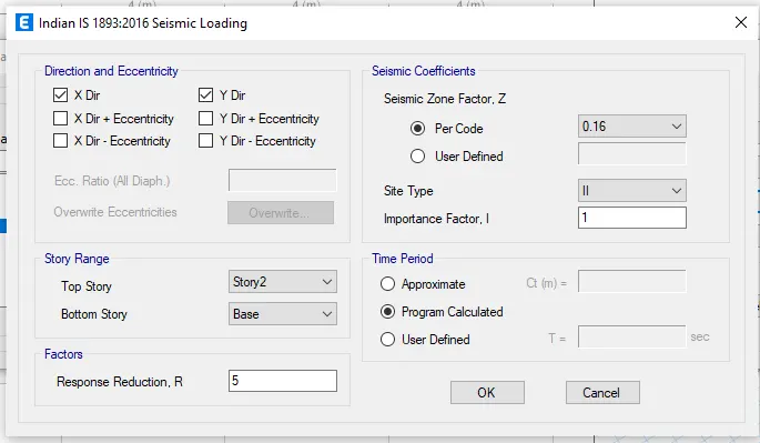
12. Go to Sesmic Loading and select it to X direction
13. Go to Sesmic Loading and select it to Y direction
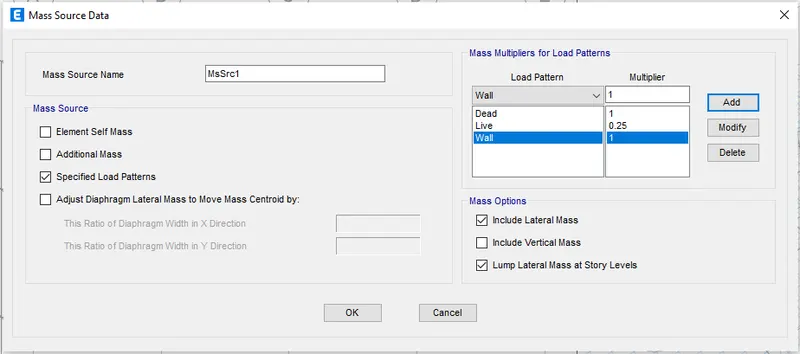
14. Go to mass source Data
15. First select Load pattern Live to 25%
16. Then select Load pattern Dead to 100%
17. Select Wall Load Pattern 100%
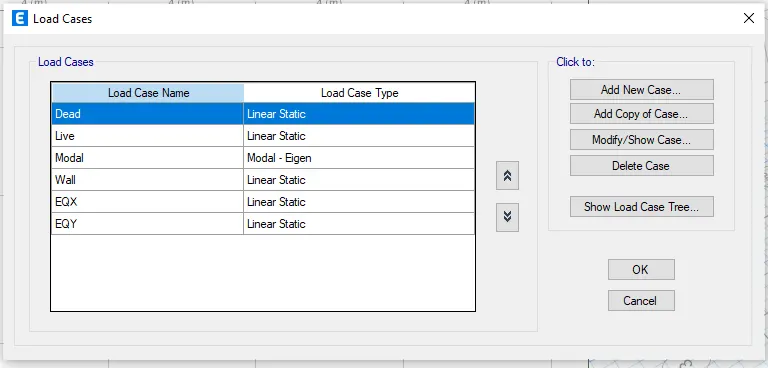
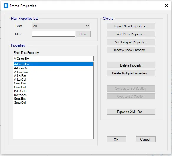
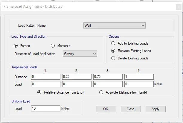
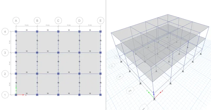
18. Go to frame Load Assignment and Select the Wall Load to 10KN/m
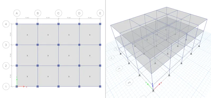
19. Then go to Define and select Slab section
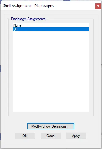
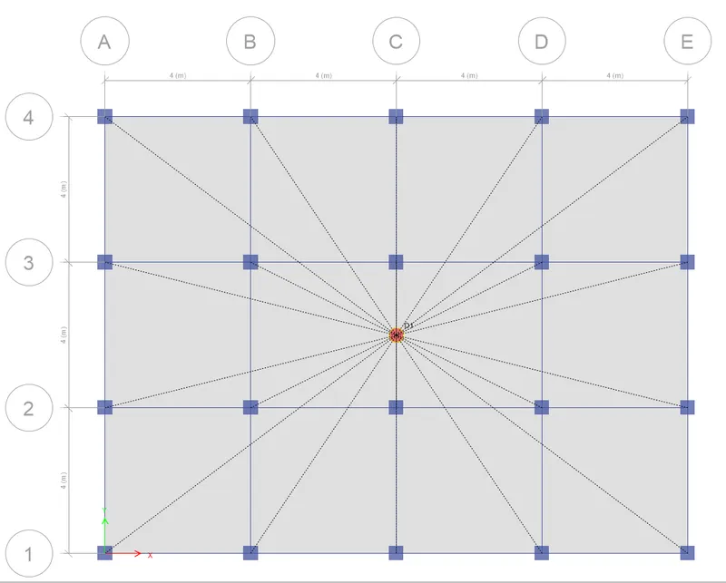
20. Then go to Assign and select the Diapragm
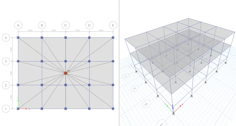
21. Then Run Analysis
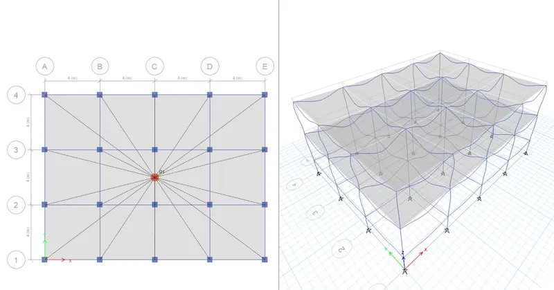
Model B
22. Save as Model A
23. Now Go to Moddel B
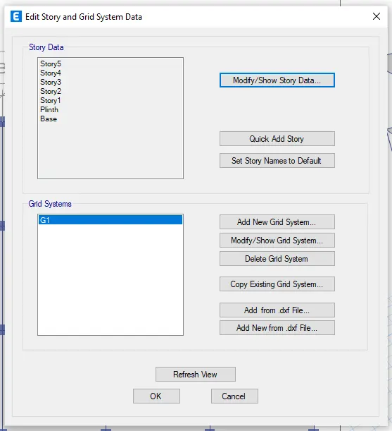
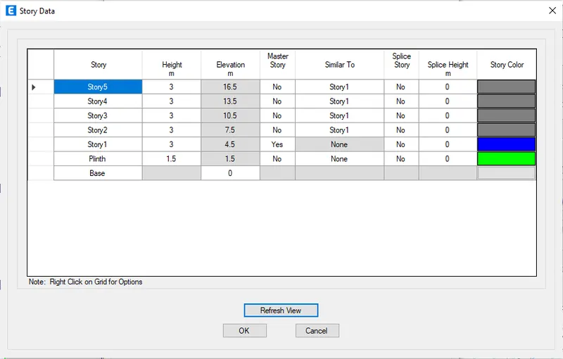
24. Increase the no. of storey according the attachment
26. Add the 5 no. of storey
27. Select the Similar storey to Storey 1
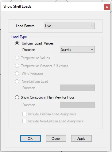
28. Go to Select and select the shell Load
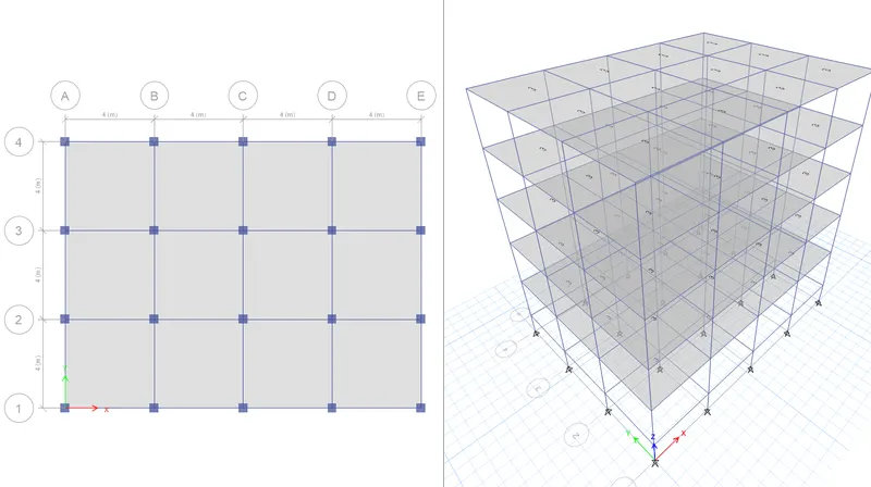
29. Select it to Live Load
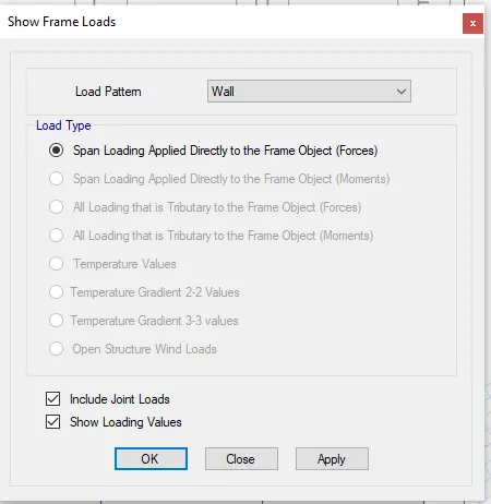
30. Select the Load to Wall Load
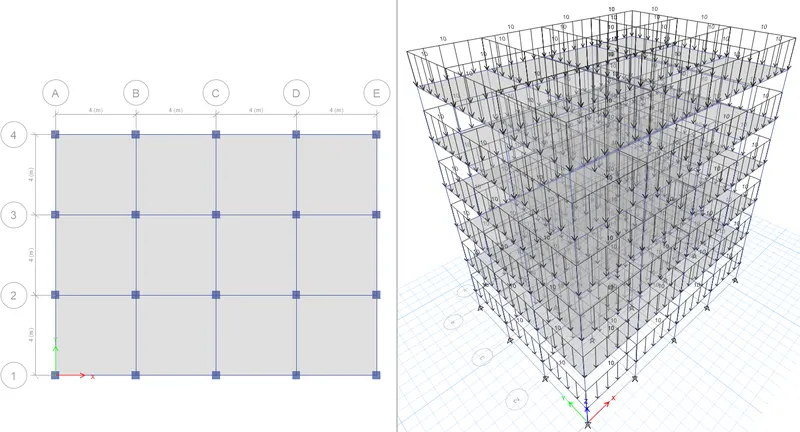
31. It will appear in this way
32. Then go to Define and select Slab section
33. Then go to Assign and select the Diapragm
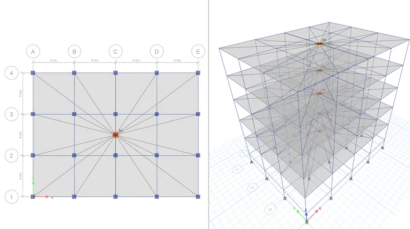
Model C
34. Create a new Model and save it as C
35. Now change the Column size to 550 X 300
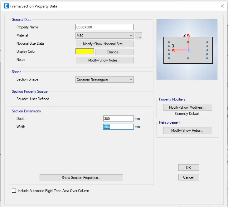
36. Select the Orientation in X Axis
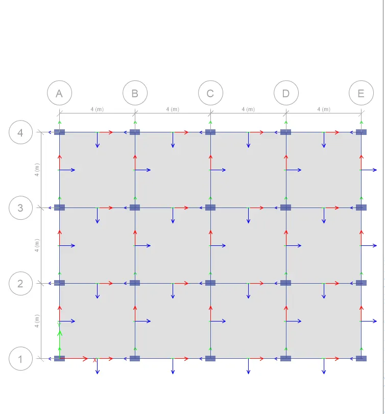
37. Select the Slab section and then Go to Assign and select the diaphragm
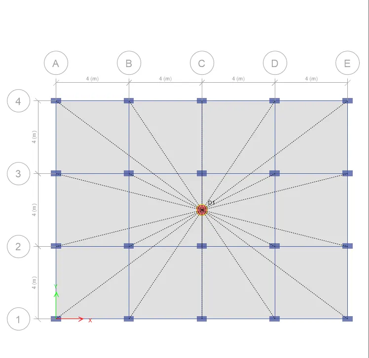
Model D
38. Then go to the Model D
39. Select Orientation in Y axis
40. Select the Slab section and then Go to Assign and select the diaphragm
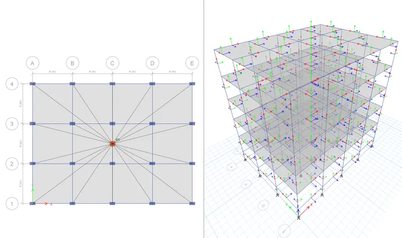
41. Then Run Analysis
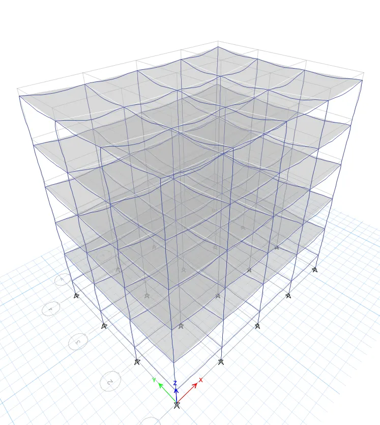
Model E
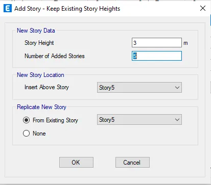
42. Save the Model as Model E and then Go to Add storey and then Select it to 5
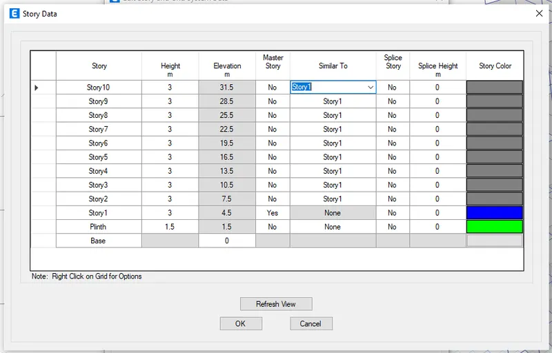
43. Then select the Storey to total 10 Storey
44. Then go to Assign and then assign Load
45. Select the Live Load
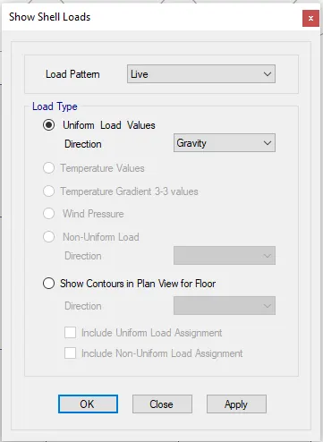
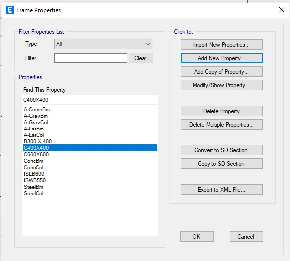
46. Select the Column Size to 400X400
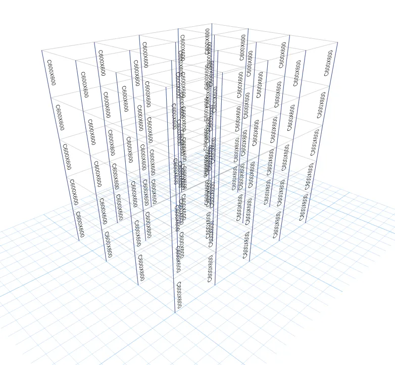
47. Select the Shell and then Assign it to Diphragm
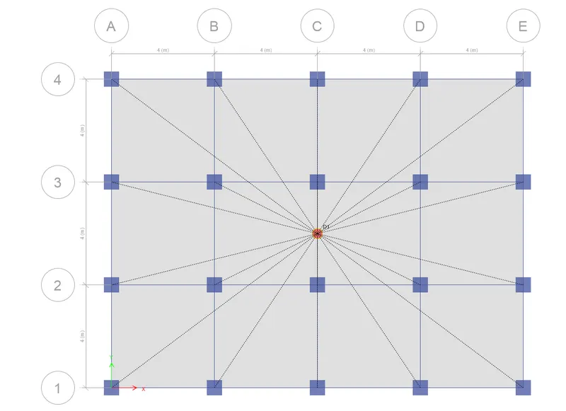
48. Then Run Analysis
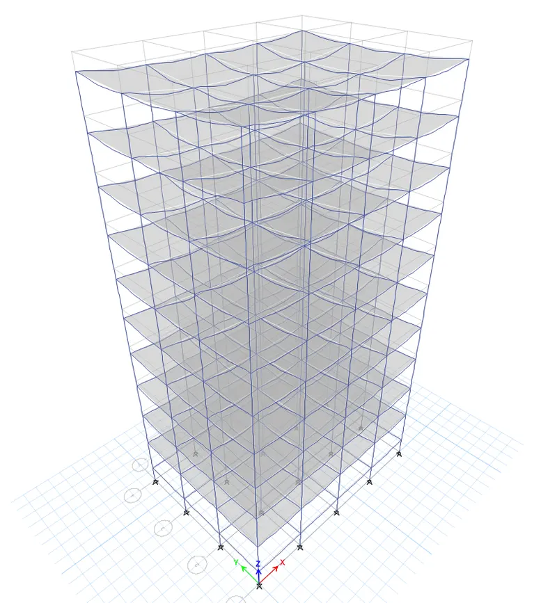
Model F
49. Then Select the a New Model
50. Increase the Floor level
51. And select the Similar Floor to Storey 1
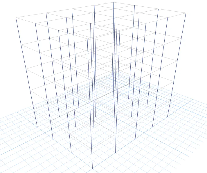
56. Then go to Set Display Option
57. Now un select the Beam and Floor
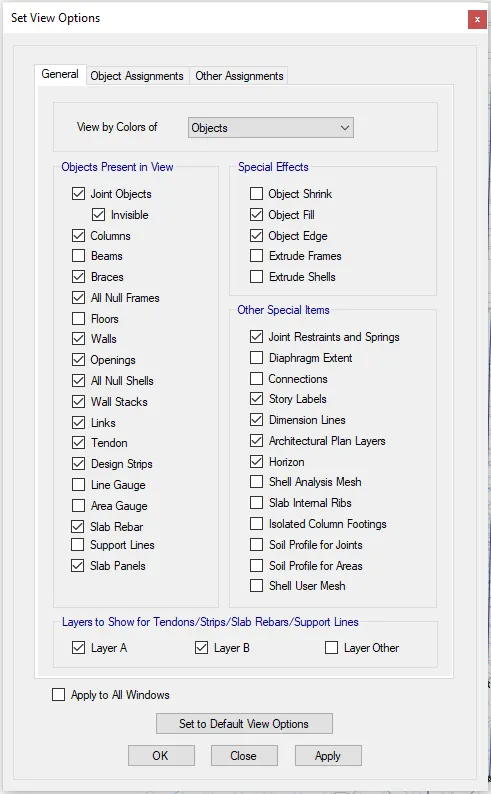
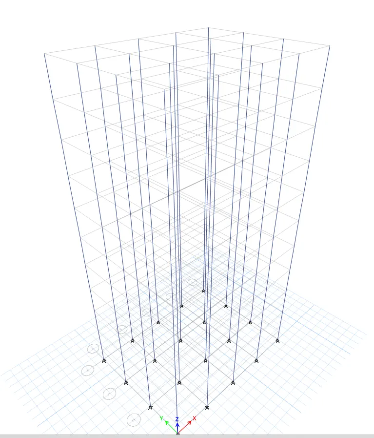
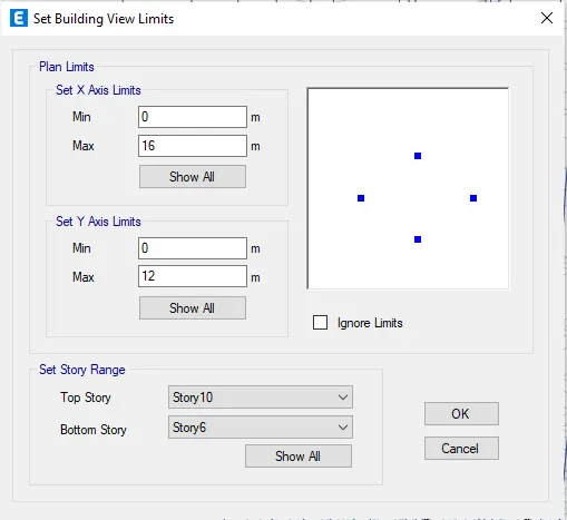
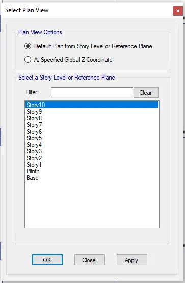
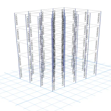
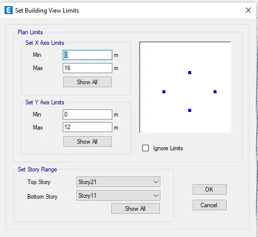
57. Select the Building View Limit from 6 Storey to 10 Storey
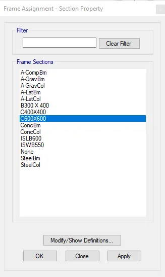
58. After Selecting the Floor Change the Column Size and Apply it
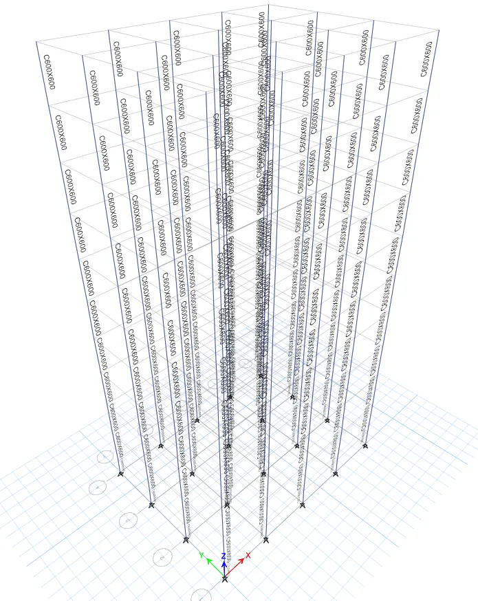
60. Then apply the Shell Unifrom Load
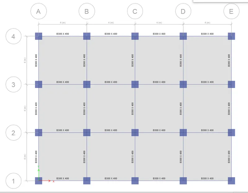
61. Select the Slab Section
62. And then go to Assign and then Select the Diaphragm
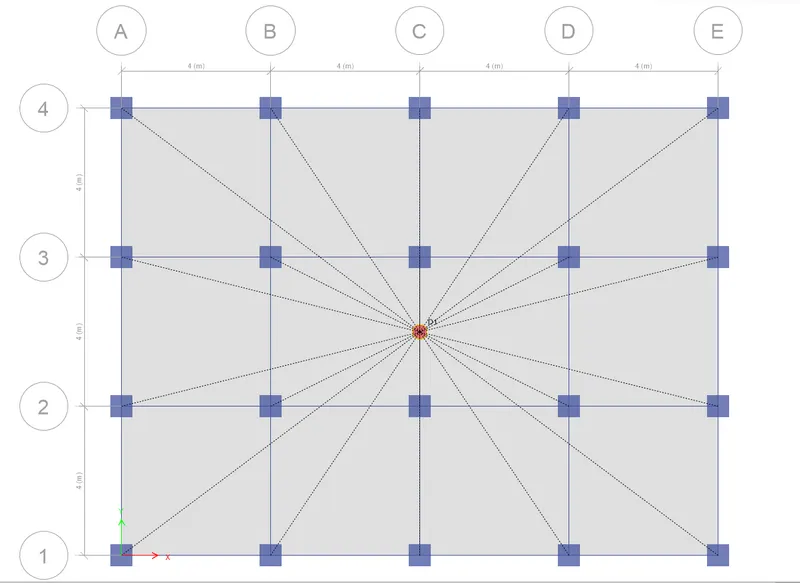
63. After selecting and assigning the Diaphragm
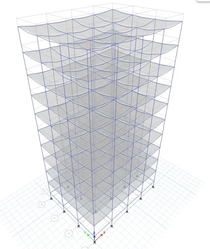
64. Select the Run analysis
Model G
65. Go to Model G
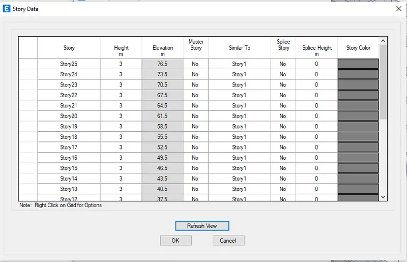
66. Save it as Model G
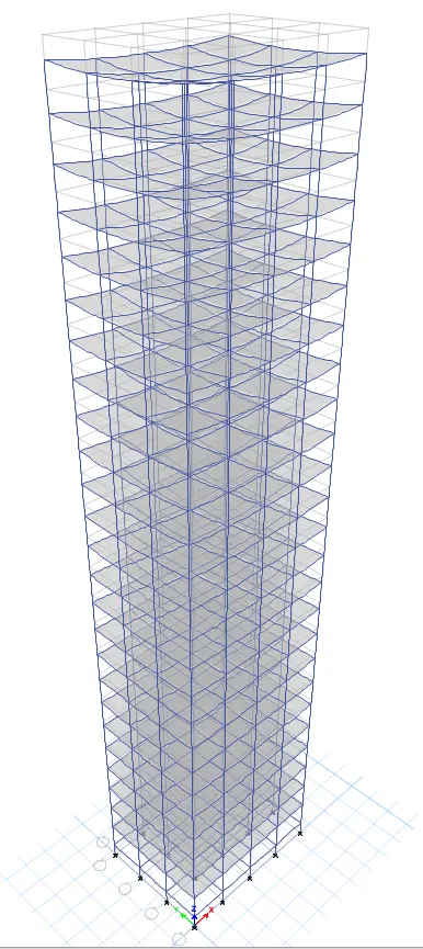
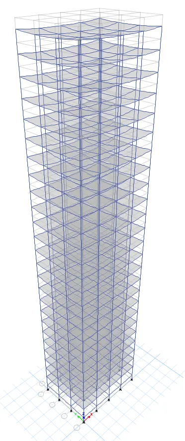
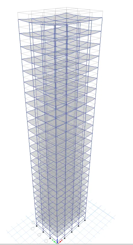
67. Increase the no. of Storey to total 25 Storey
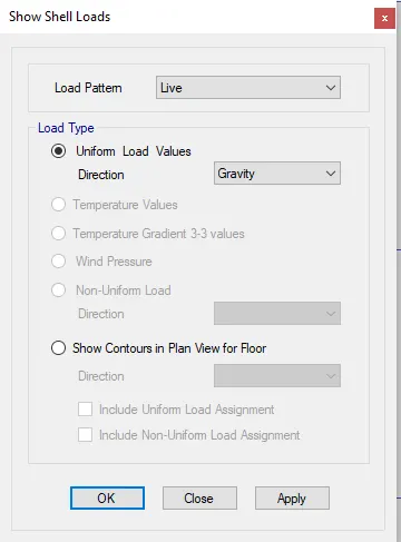
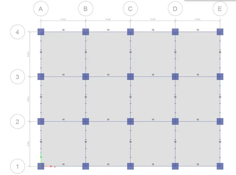
68. Then Select the Shell loads to Live 10kn/m
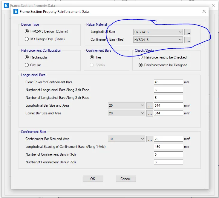
69. Select the Longitudinal Bars and Confinement Bars To HYSD415
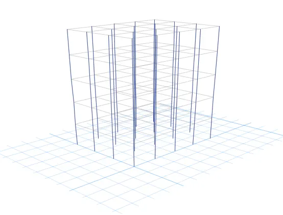
70. Select Storey 21 to 25 and change the Bars to 400X400
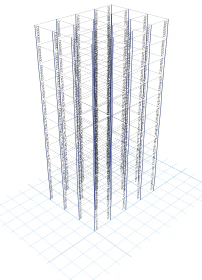
71. Now select the Floors to Storey 11 to 21
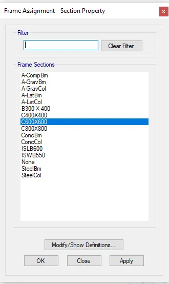
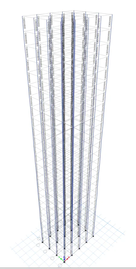
72. Select the Storey Column to 600 X 600
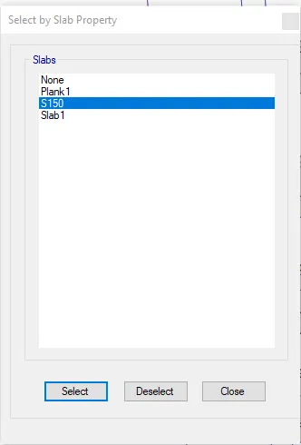
73. Select the Slab 150
74. And then Assign the Diaphram
75. And Run Analysis
Model H
76. Select the New Model and save it as Model H
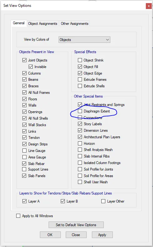
77. Select the Slab 150
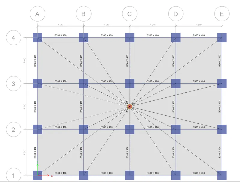
78. And then Assign the Diaphram
79. And Run Analysis
Model I
80. Save the New model as Model I
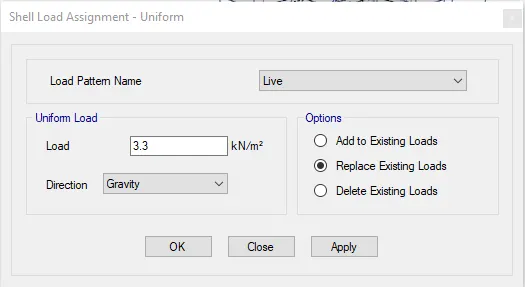
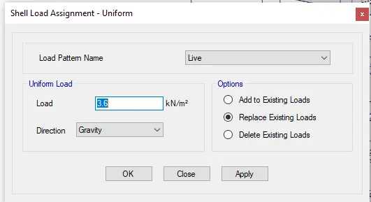
81. Select the shell load to Live to 3.3 kn/m2
82. Keep the column size same as model H
83. And then Run Analysis
Model J
80. Save the New model as Model J
81. Select the shell load to Live to 3.6 kn/m2in crease it by 10%
82. Keep the column size same as model H
83. Select the the Column Size same as of Model I
84. Select the Slab Section 150
85. Assign the Diphragm
86. And then Run Analysis
Mode periods and Frequency for Building C
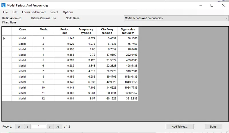
Mode periods and Frequency for Building D
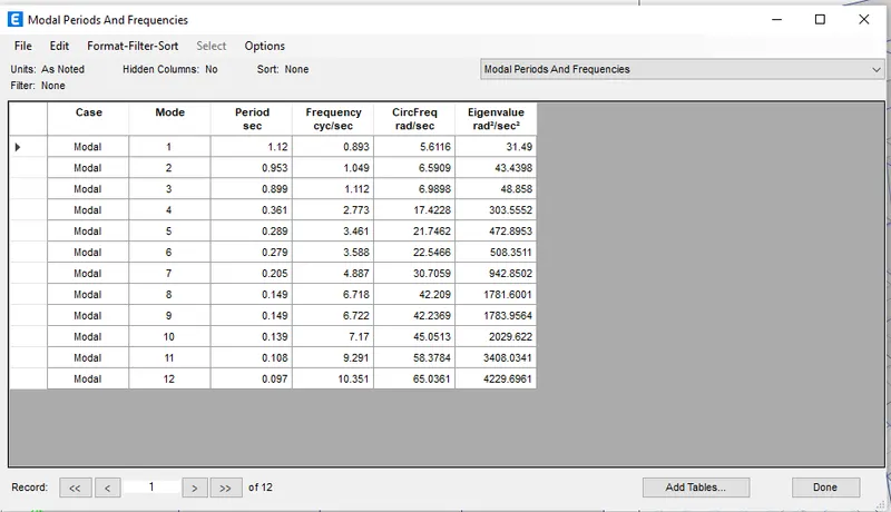
Mode periods and Frequency for Building E
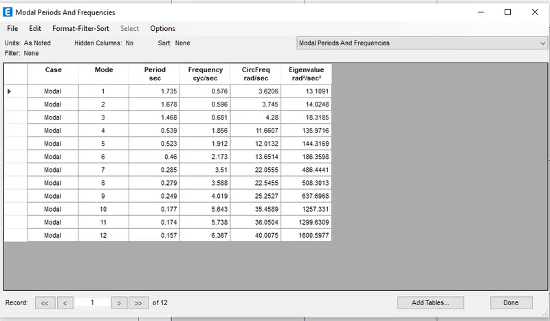
Mode periods and Frequency for Building F
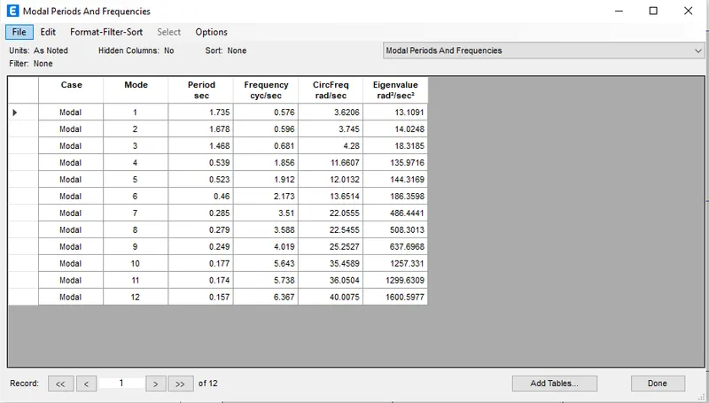
Mode periods and Frequency for Building G
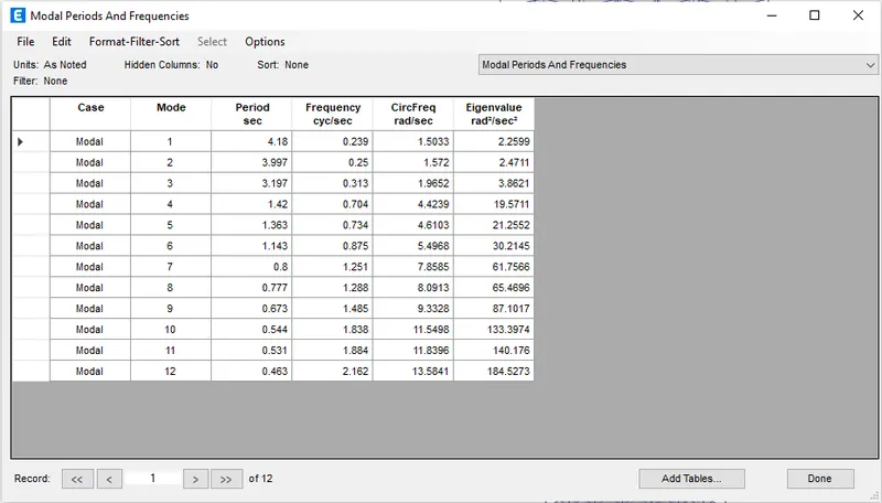
Mode periods and Frequency for Building H
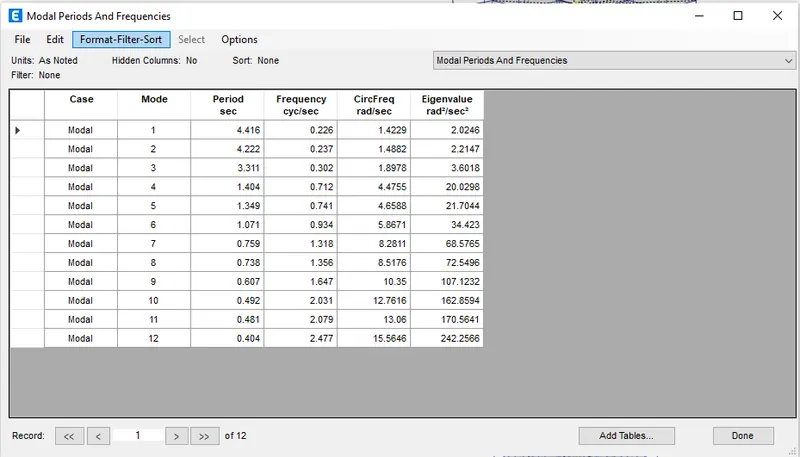
Mode periods and Frequency for Building I
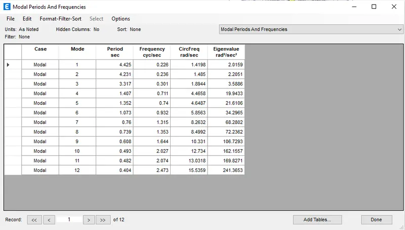
Mode periods and Frequency for Building J
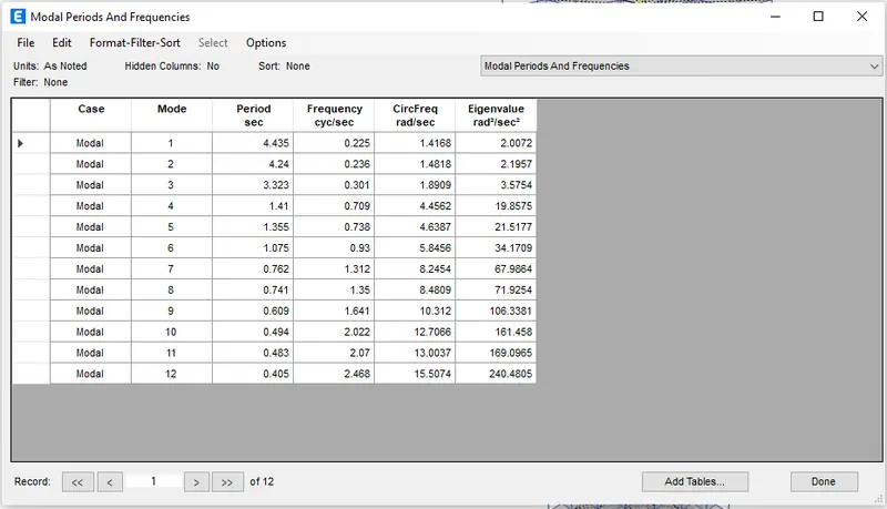
Conclusion : Hence the Project 1 is Complete