Project 1_Comparative study of different storey buildings for Seismic forces
PROJECT
Comparative Study of Different Story Buildings for Seismic Forces
AIM: TO MODEL AND ANALYZE MULTIPLE BUILDINGS WITH DIFFERENT FLOOR LEVELS AND DESIGN PARAMETERS USING ETABS SOFTWARE AND COMPARE THE RESULTS TO UNDERSTAND THEIR OVERALL SEISMIC BEHAVIOUR.
INTRODUCTION:
The structural configuration of the building plays a major role in determining the overall response during an earthquake. Different building geometries behave differently when induced by the same seismic forces. Hence, it is very important to properly understand the response of buildings related to their structural configurations for a safer design approach.
DETAILED PROCEDURE:
1. BUILDING "A" (G+2)
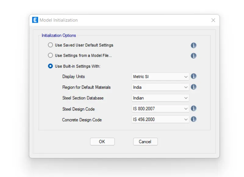
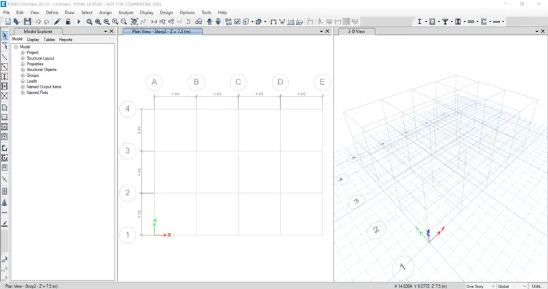
- Open ETABS and Set up the Model OF THE G+2 BUILDING
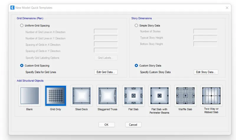
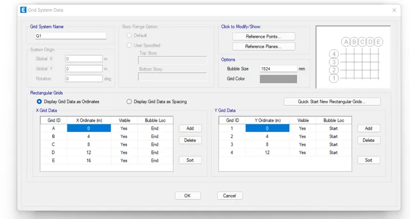
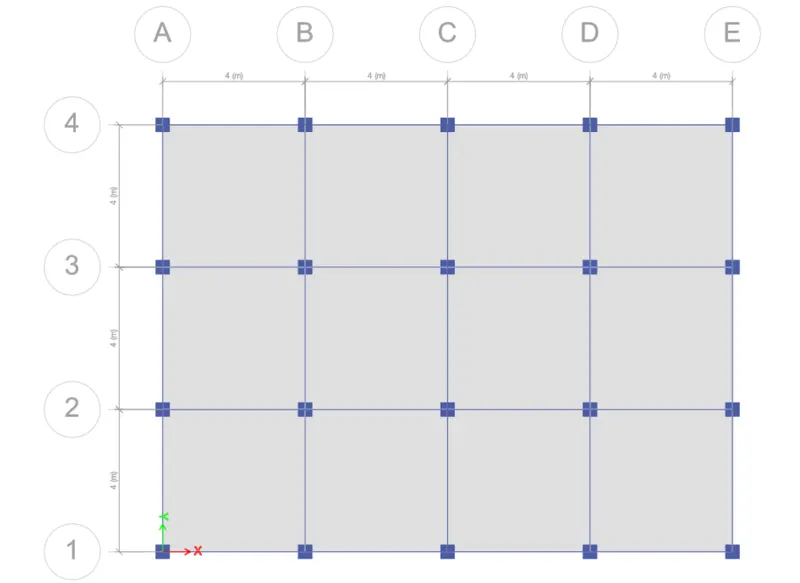
- Setting up the Grid Data
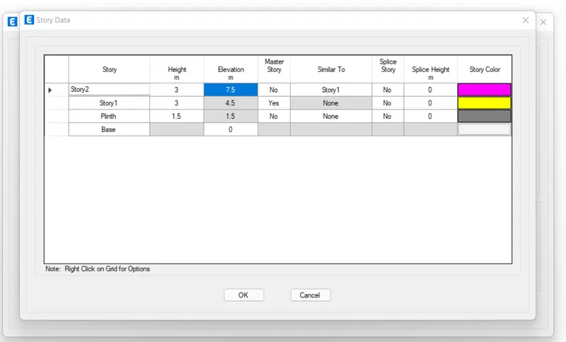
- Fixing the Story Data
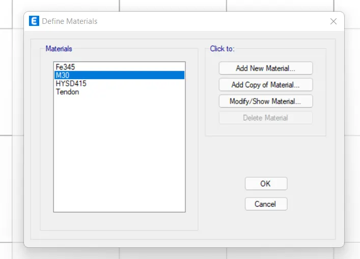
- Defining the Material Properties
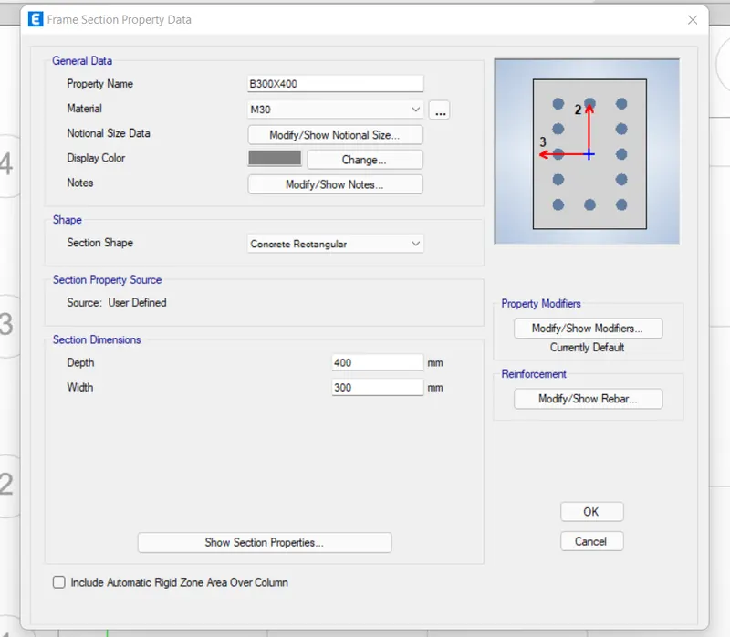
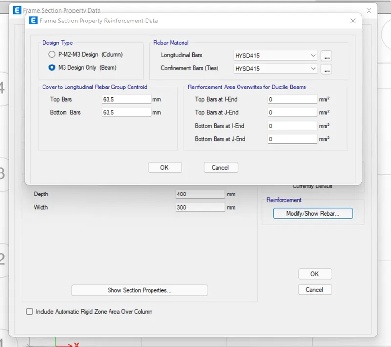
- Defining Section Properties
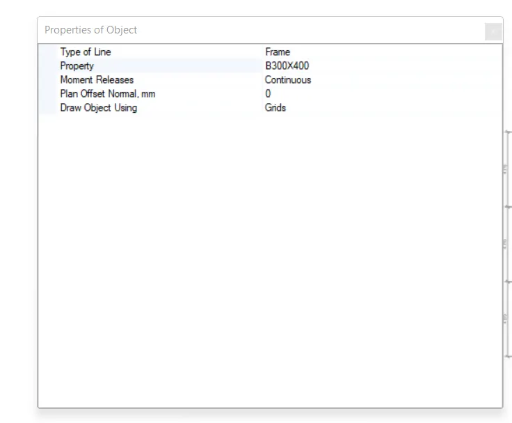
BEAM 300X400
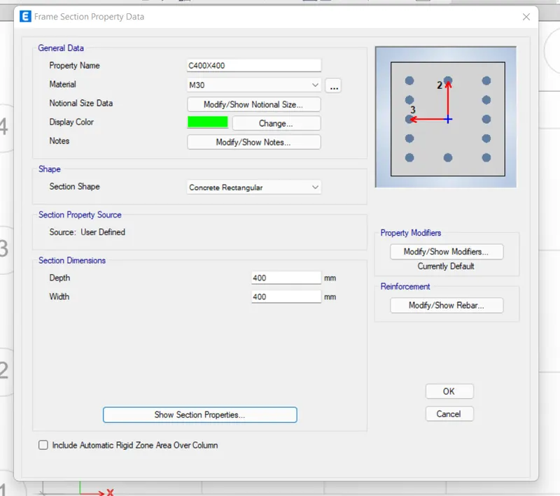
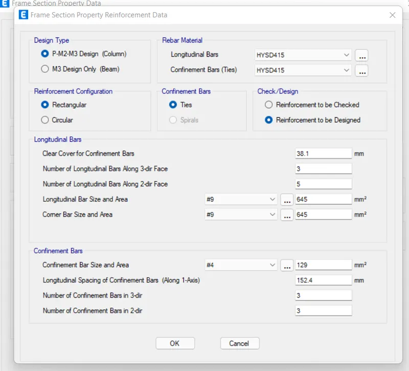
COLUMN 400X400
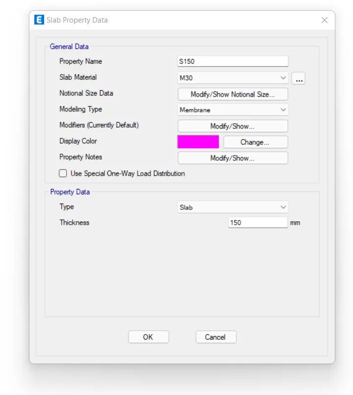
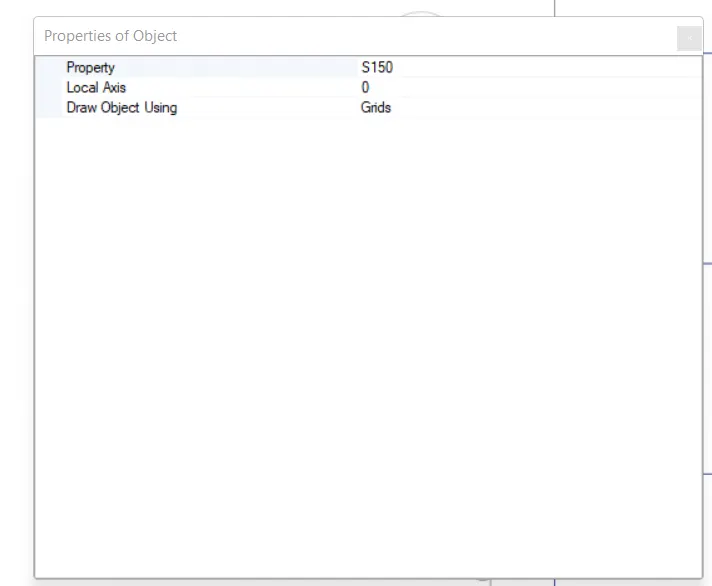
SLAB150
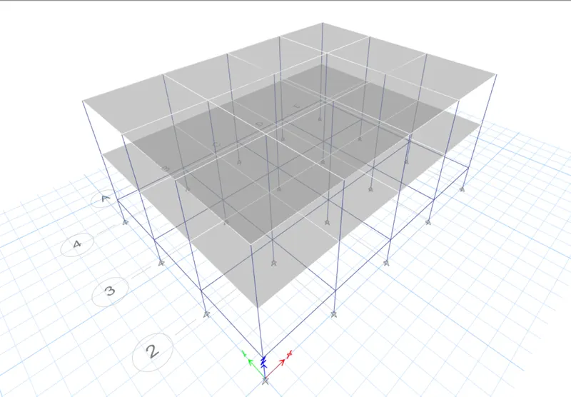
- Executing the Modeling
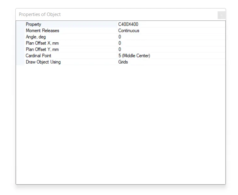
Quick Draw Columns
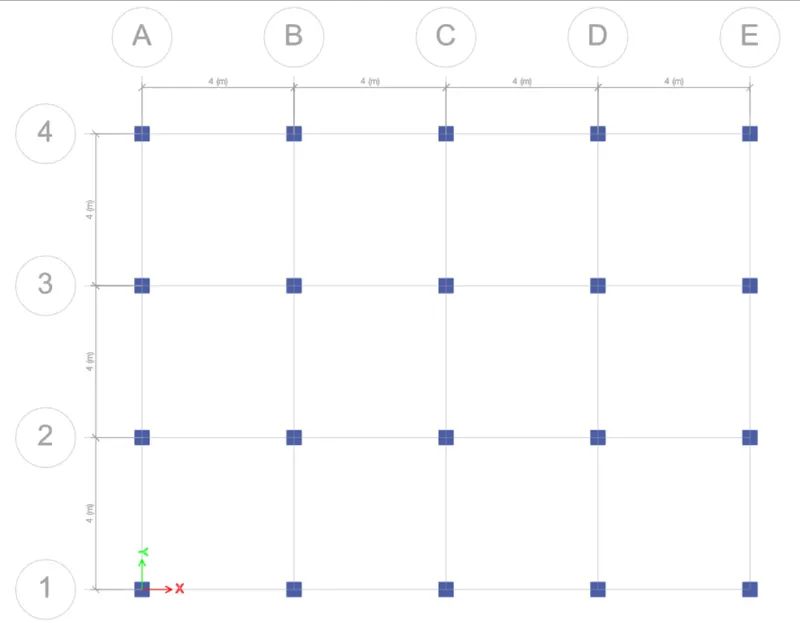
Quick Draw Beams
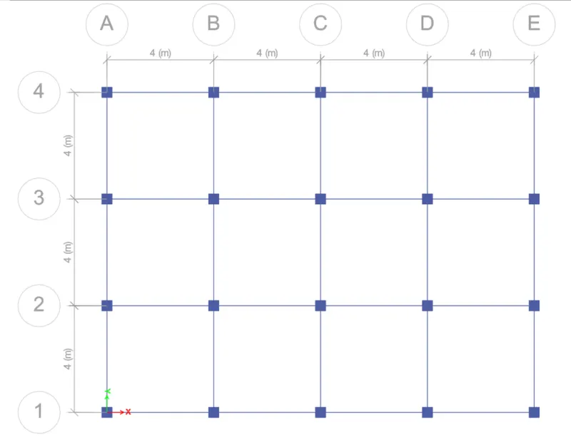
Quik Draw Floors
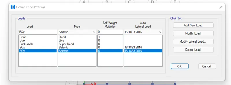
- Define the Load Patterns
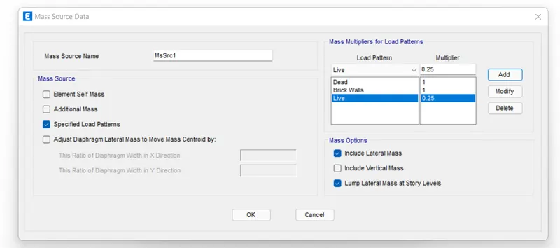
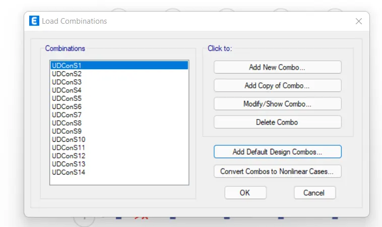
- Generate Load Combinations
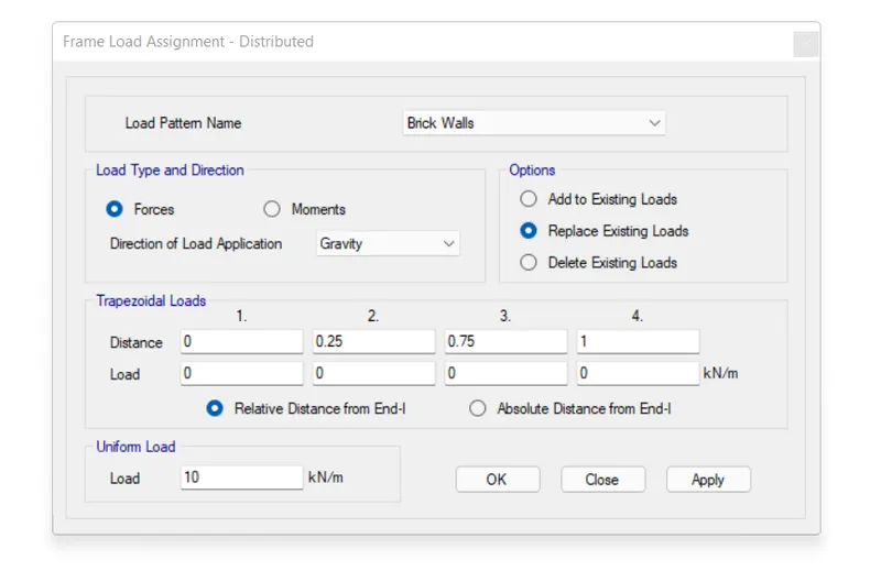
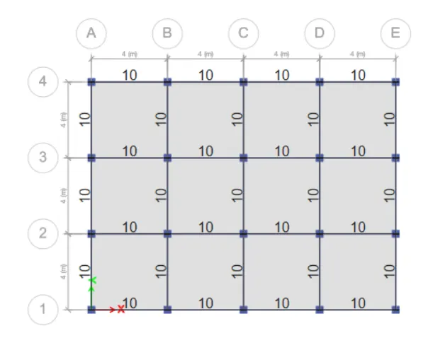
- Assign Loads to the Structural Members
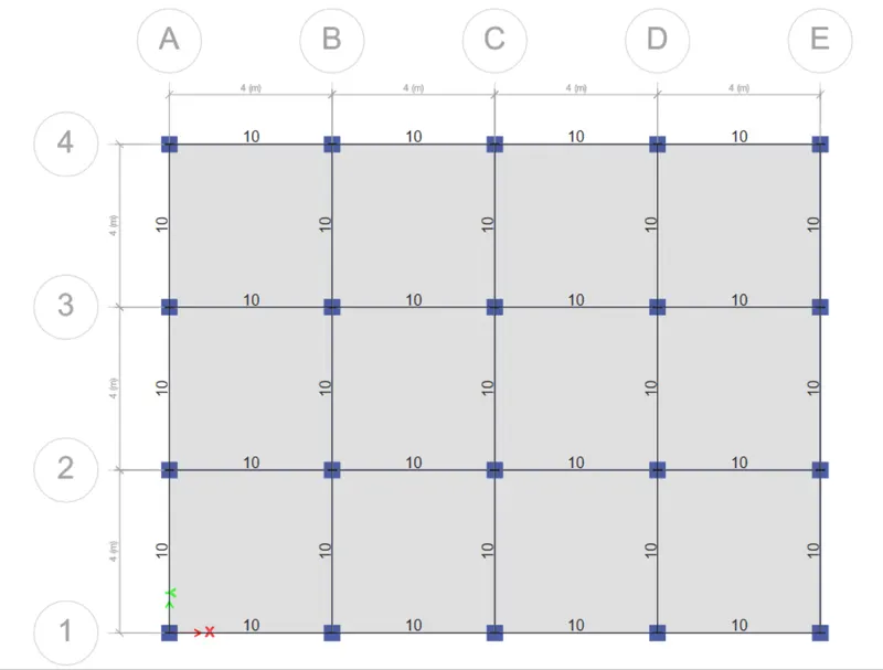
10 KN/m brick Wall
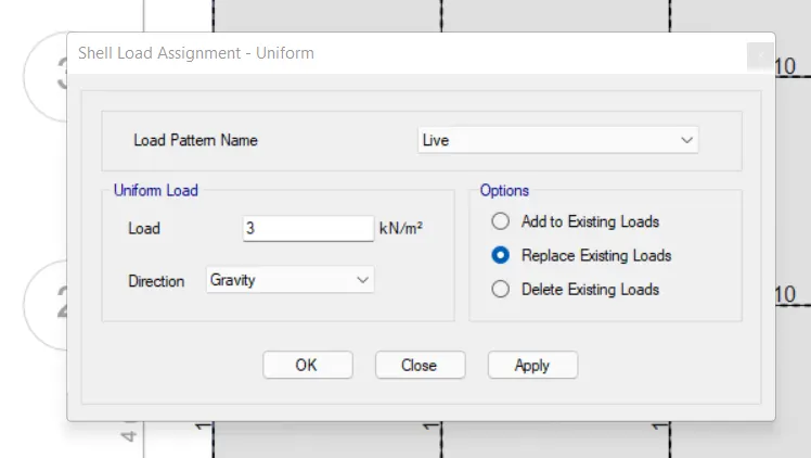
3 KN/m^2 Live Load on Slabs
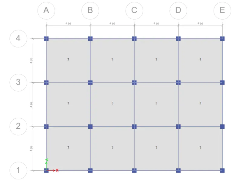
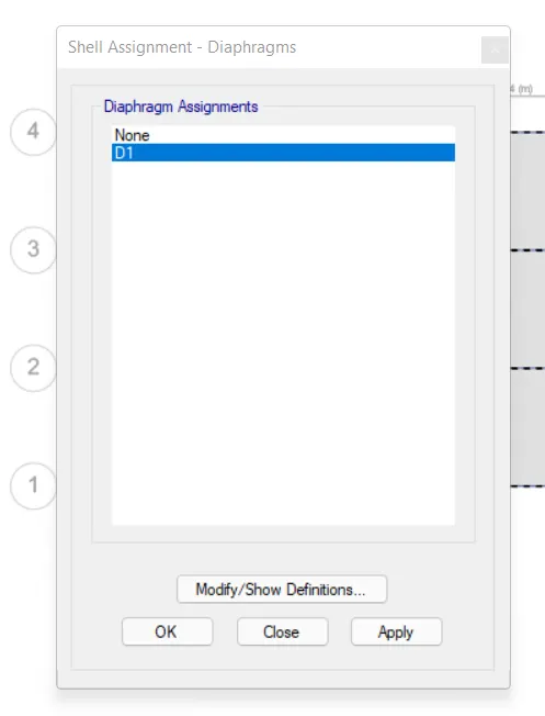
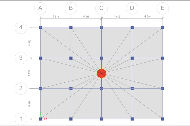
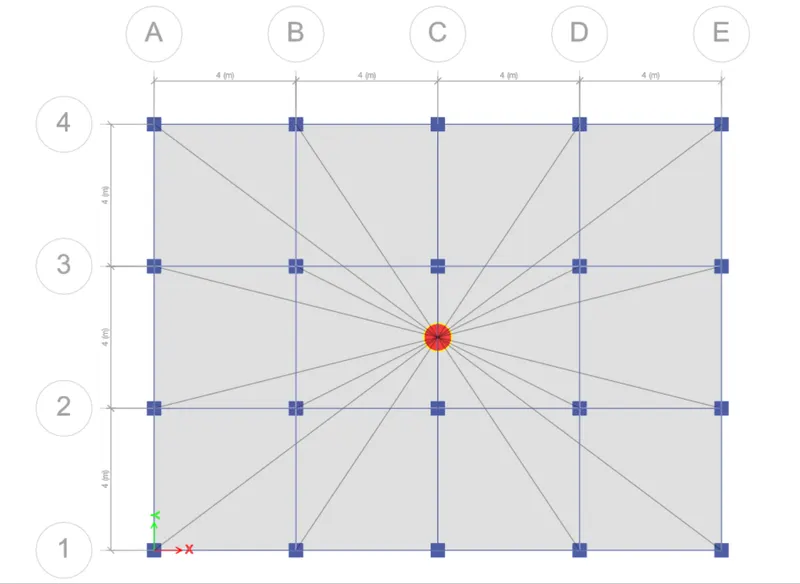
- Assign the Floor Diaphragm
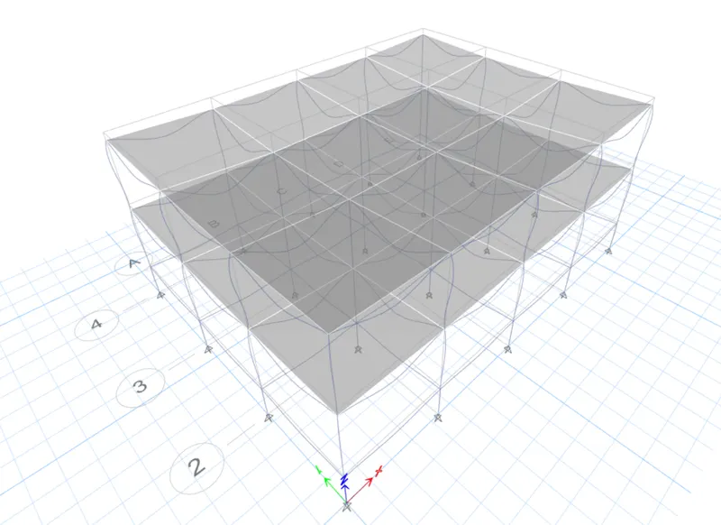
Modal Response
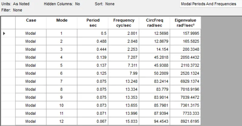
2. BUILDING "B" (G+5)
- Edit Story Data
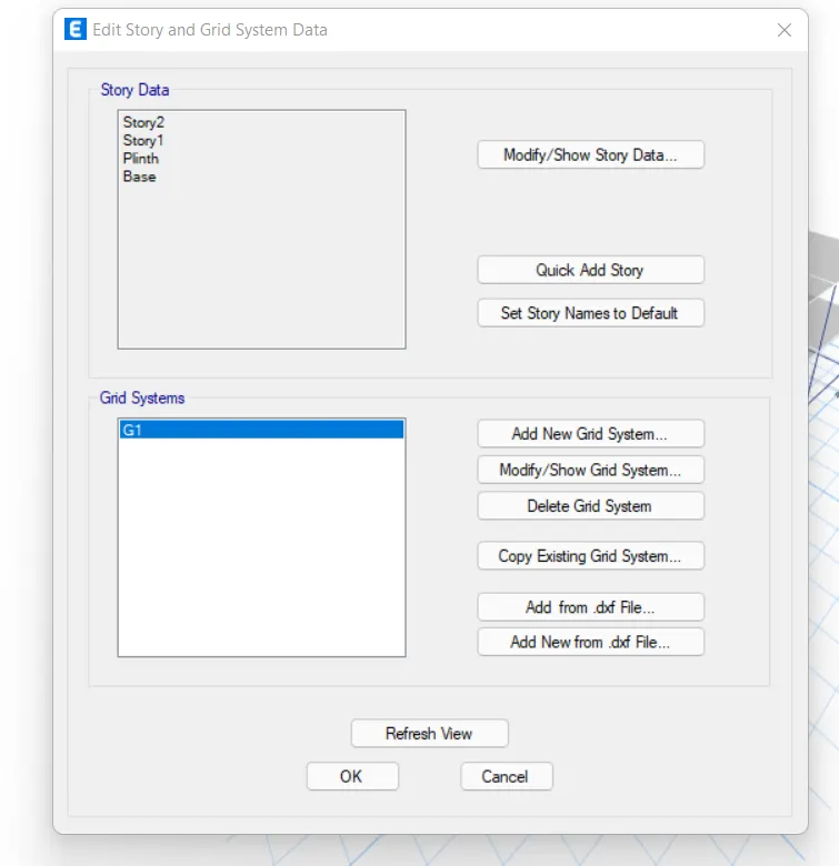
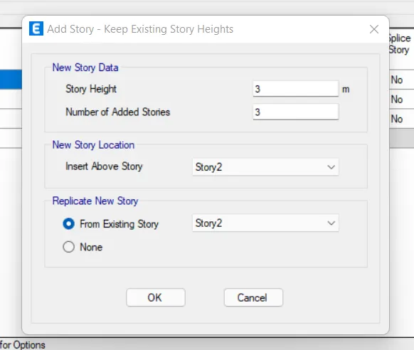
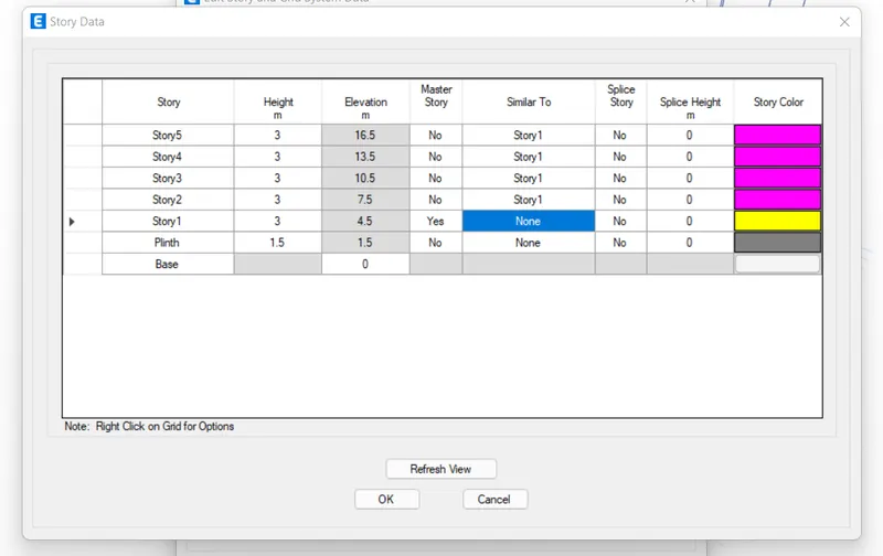
Converted 5 Story Model
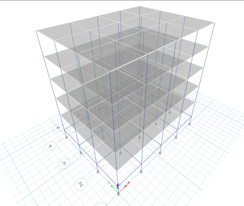
- Check the Model before Running Analysis
Check for Shell Loads
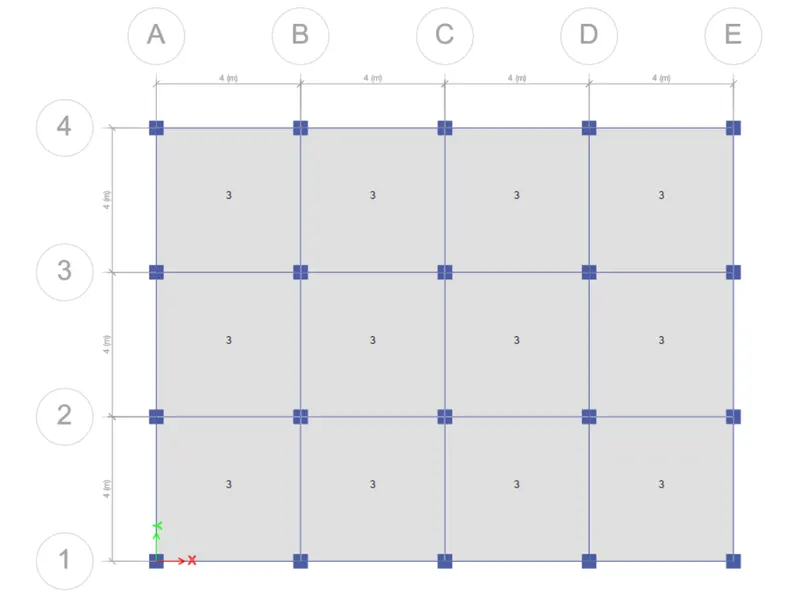
Check for the Frame Loads
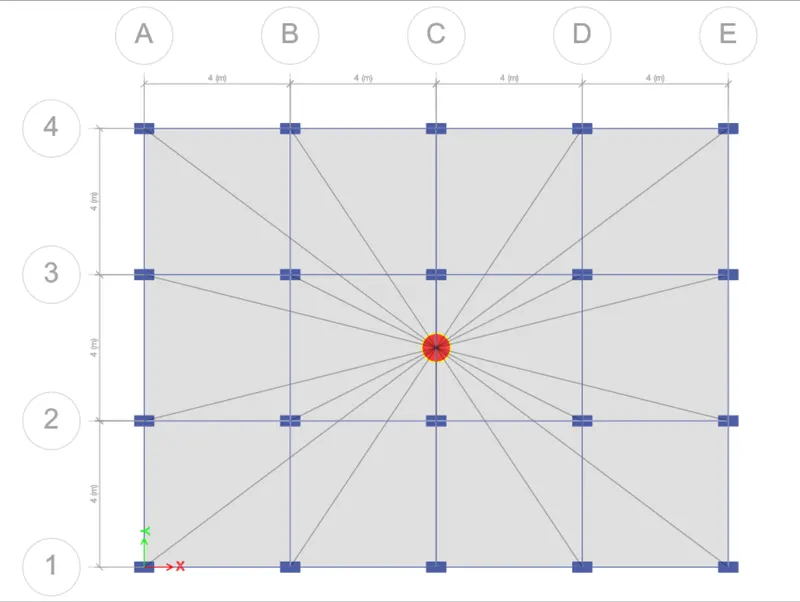
Diaphragm Check
- Run the Analysis
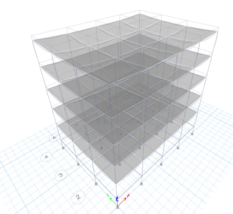
Modal Response for Building B
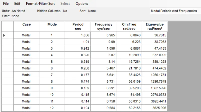
3. BUILDING "C" (G+5 with column orientation in X-direction)
- Edit the Column Size and Orientation
Required Column Section
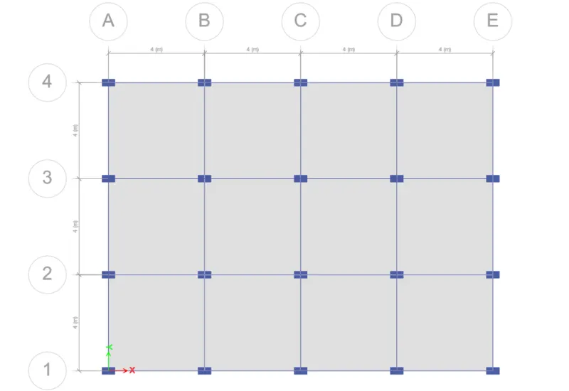
Check for the Frame loads
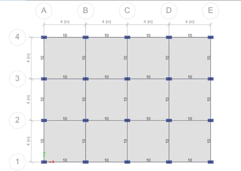
Check for the Shell Loads
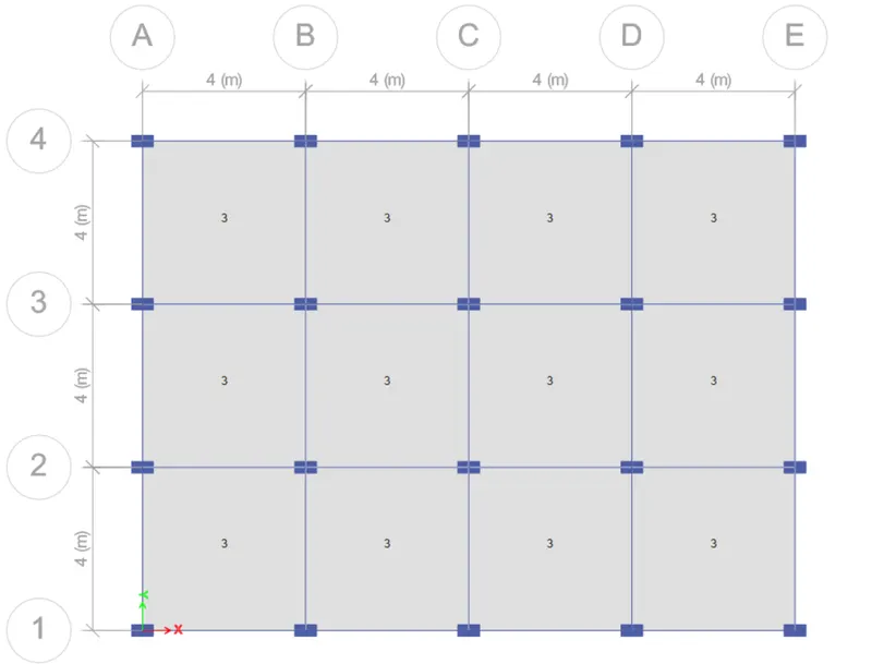
Diaphragm Check
- Run the Analysis
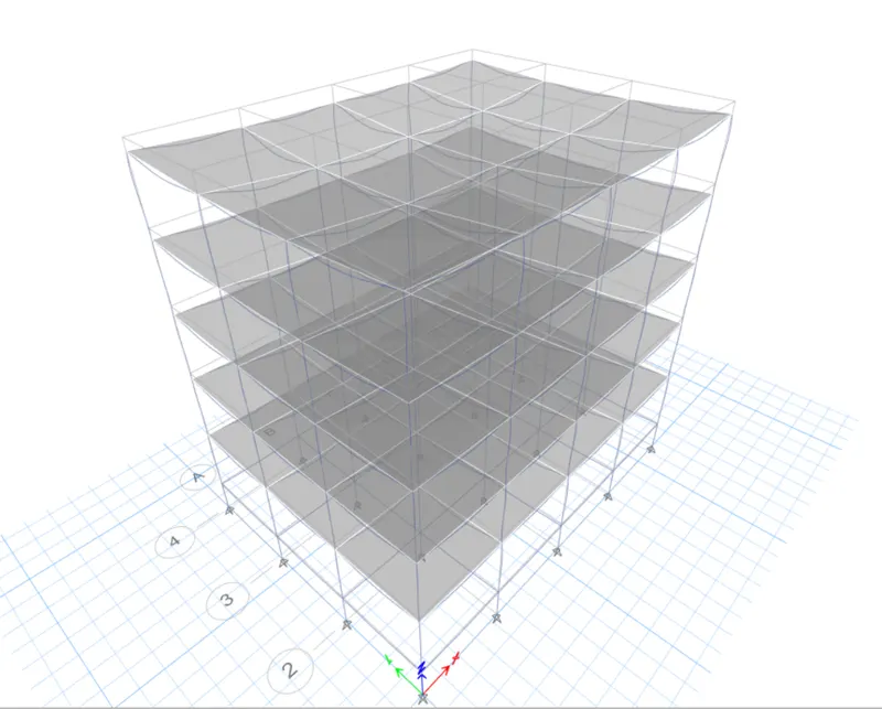
Modal Response for Building C
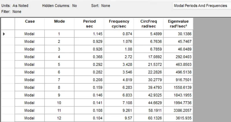
4. BUILDING "D" (G+5 WITH COLUMN ORIENTATION IN THE Y-DIRECTION)
.
- Select the Column Section and Bring the Orientation Back to Zero
(The detailed procedure to do it has already been discussed for the previous model)
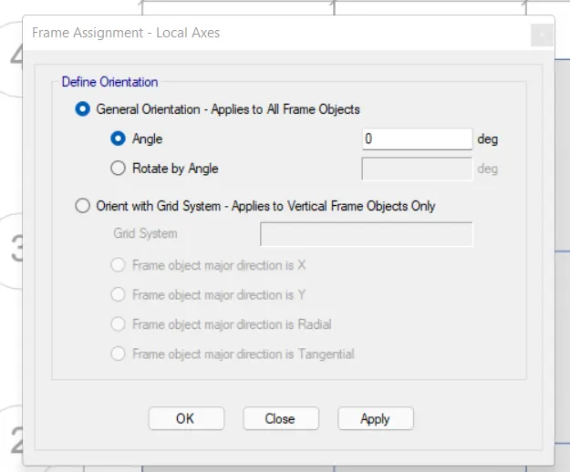
Required Column Section
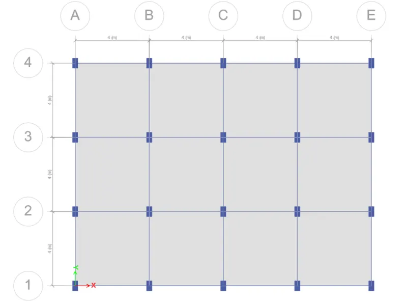
Run the Analysis
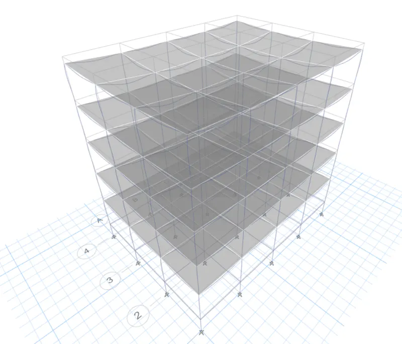
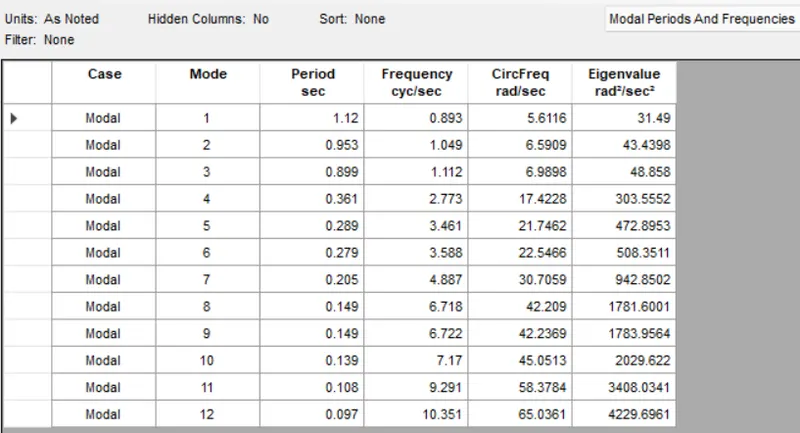
Modal Response for Building D
5. BUILDING "E" (G+10)
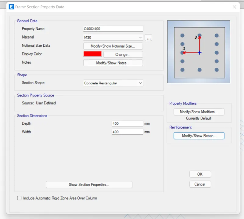
Column sizes for top 5 storeys: 400x400
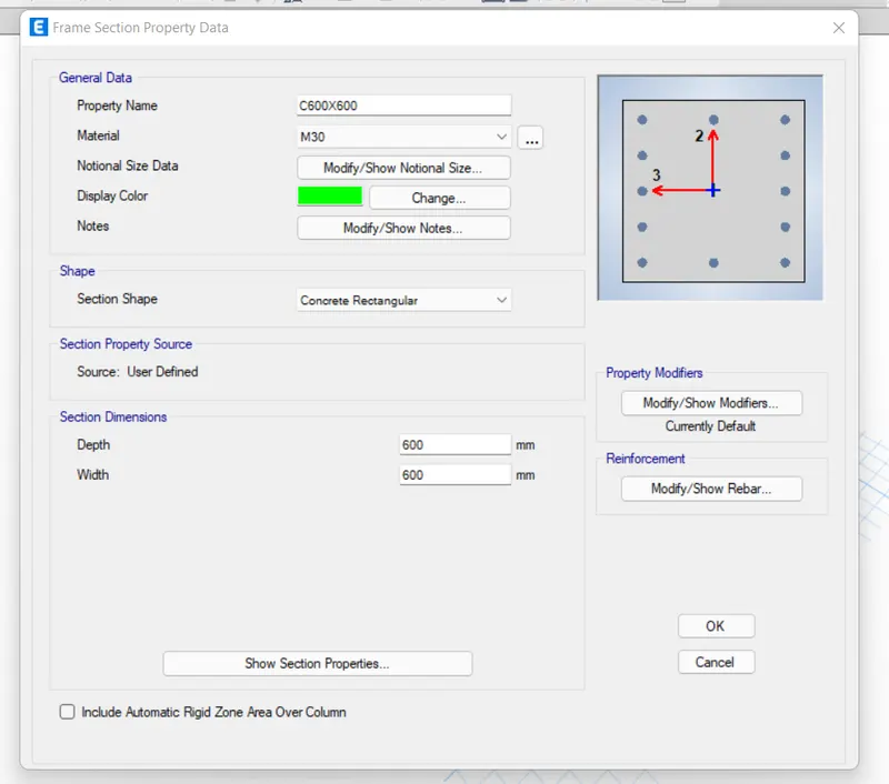
Column sizes for bottom 5 storeys: 600x600
PROCEDURE:
- Add up 5 New Stories and Set the Model for Building E
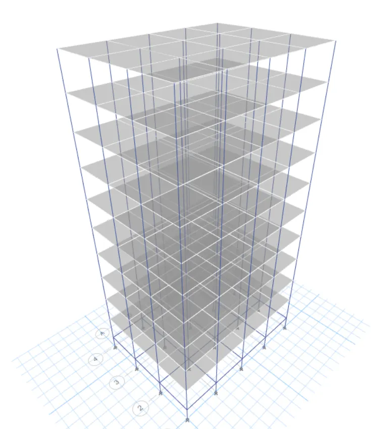
- Change the View Settings of the Model
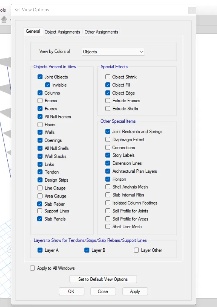
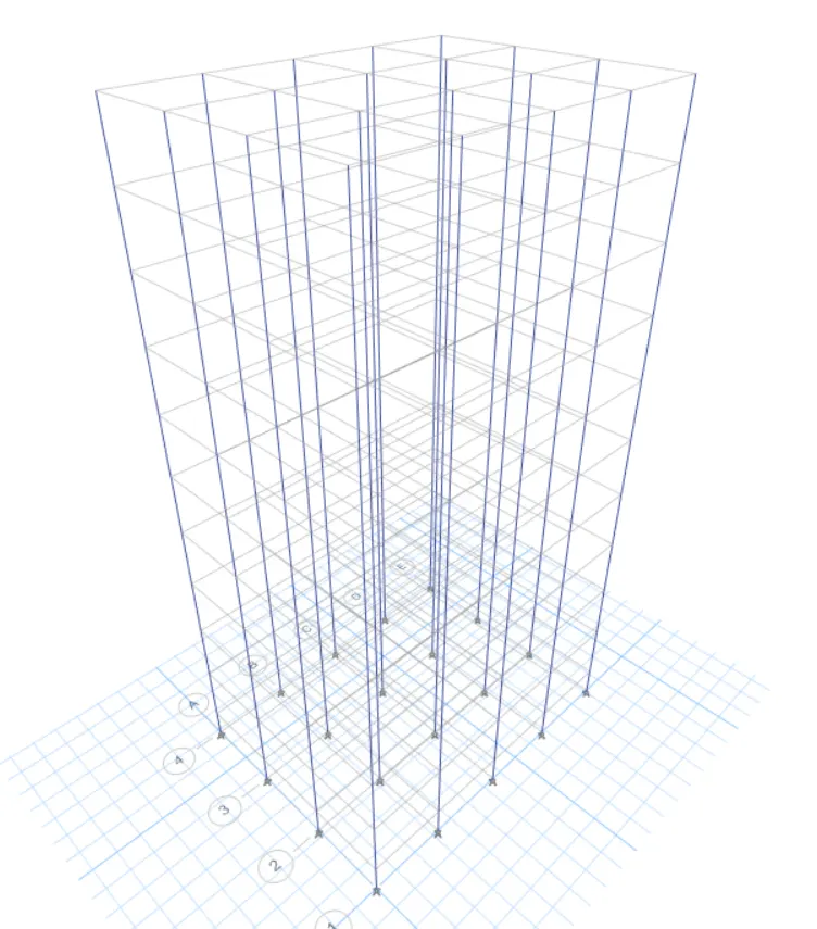
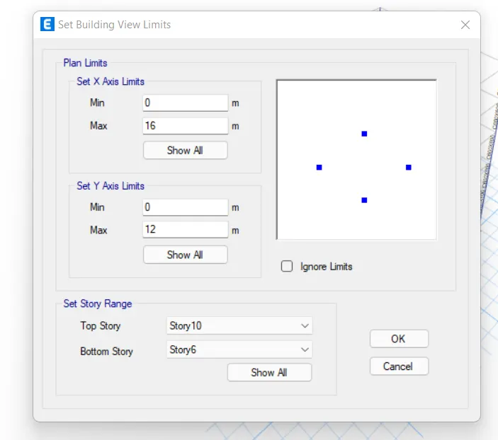
- Set the Building Limit, Select Columns, and Assign them the Required Sections
- Building Limits
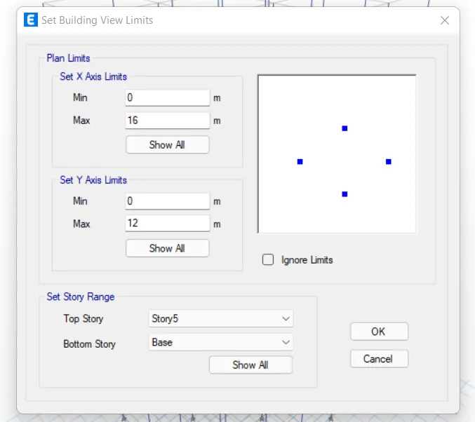
- C400X400
- C600X600
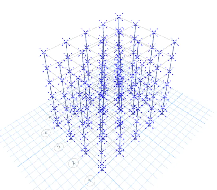
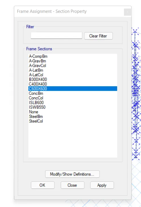
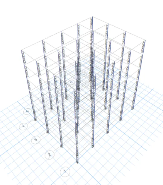
- Select Bottom 5 Story Columns
- Assign C600x600
- Building Limit for Top 5 Stories
- Select All Columns and Assign them C400x400 Section
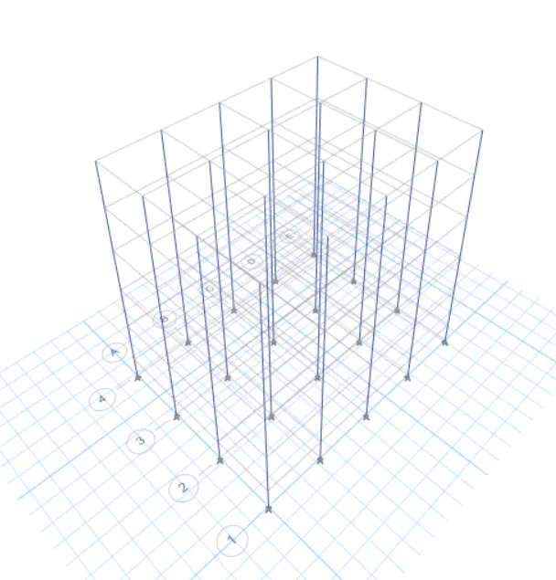
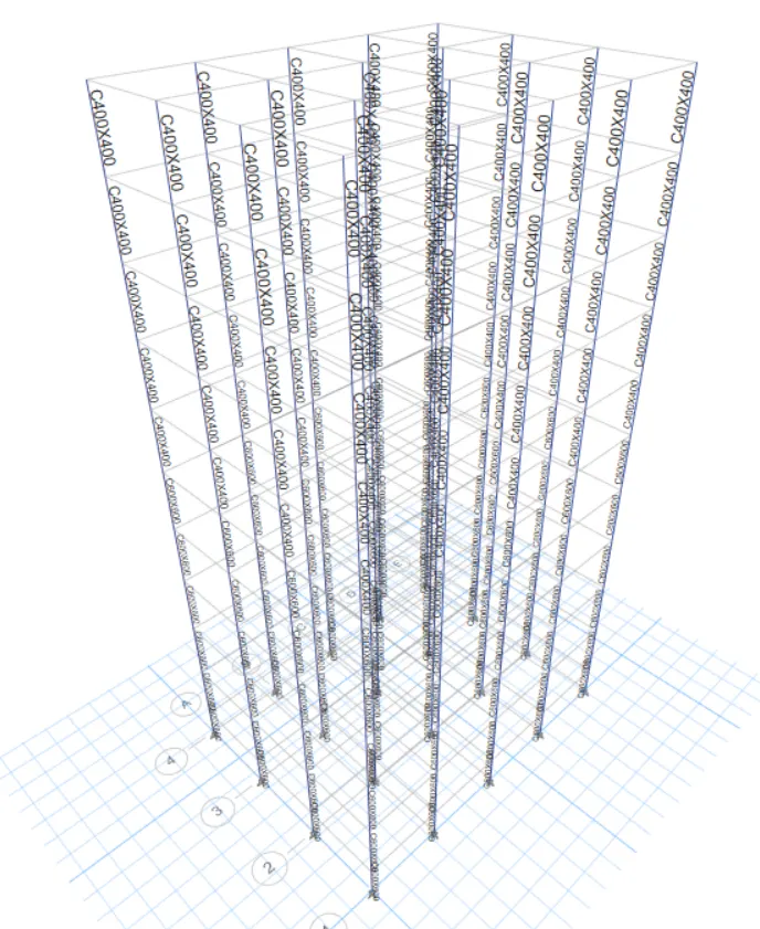
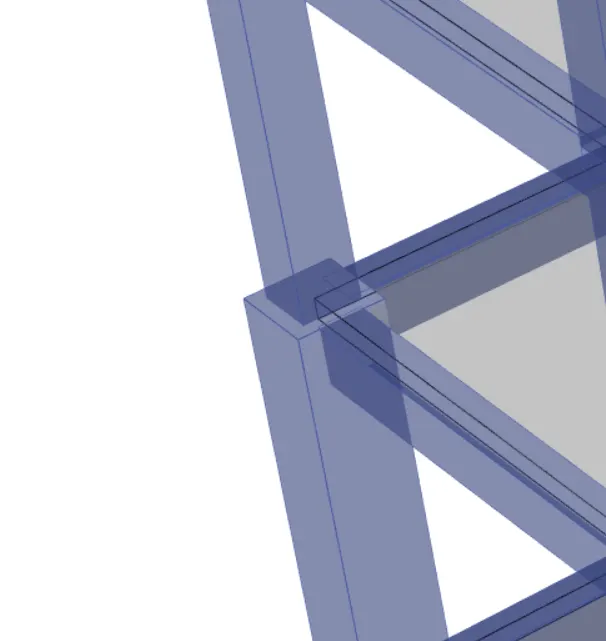
- Model After Assigning Different Columns for Different Floors
- Run the Analysis

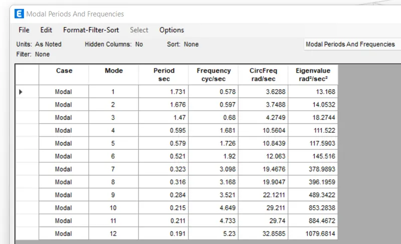
- Modal Response for Building E
6. BUILDING "F" (G+10)
- Adjust View Option Settings
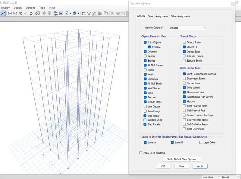
- Select all the Columns
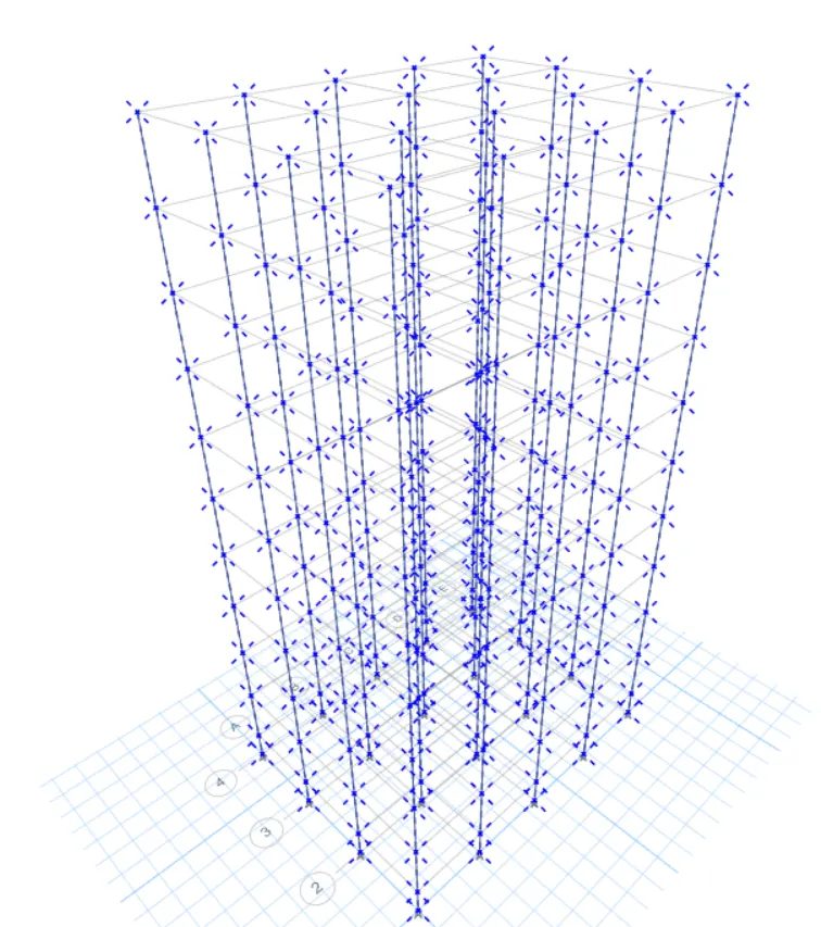
- Assign C600X600
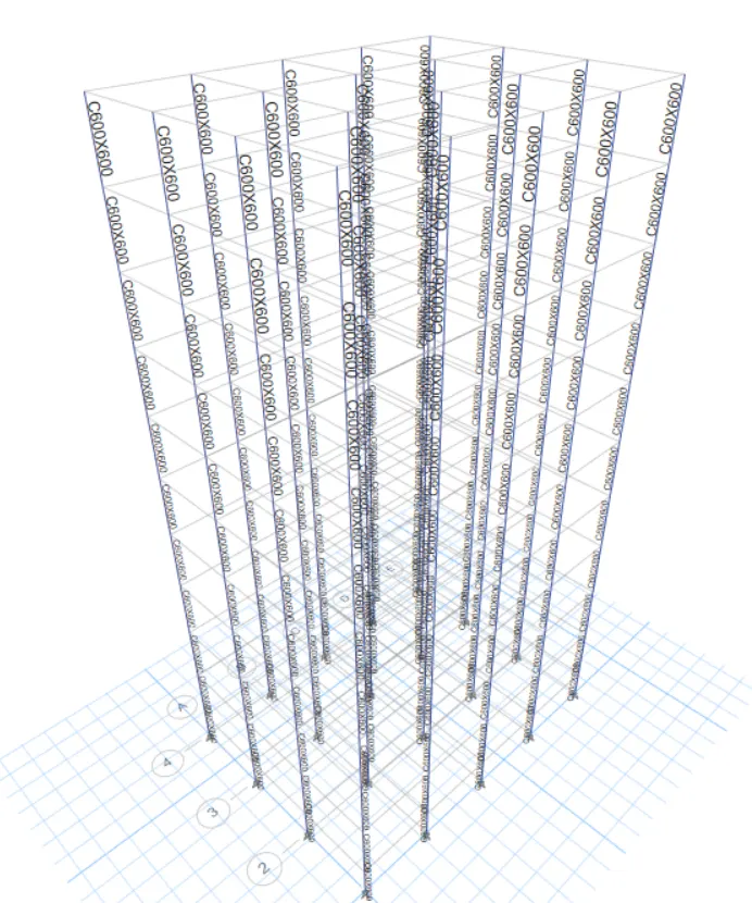
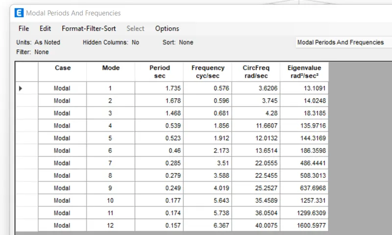
- Modal Response for Building F
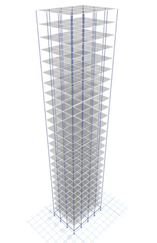
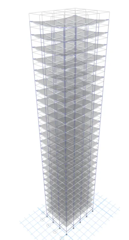
7. BUILDING G (G+25)
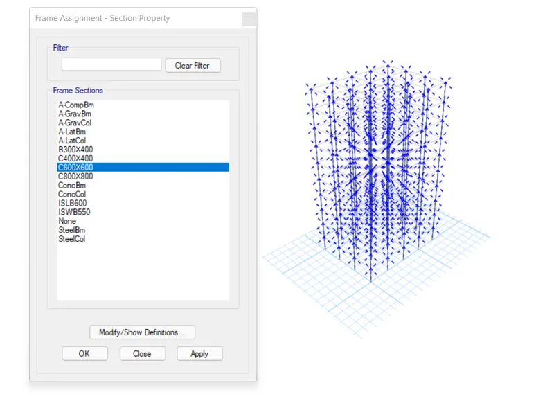
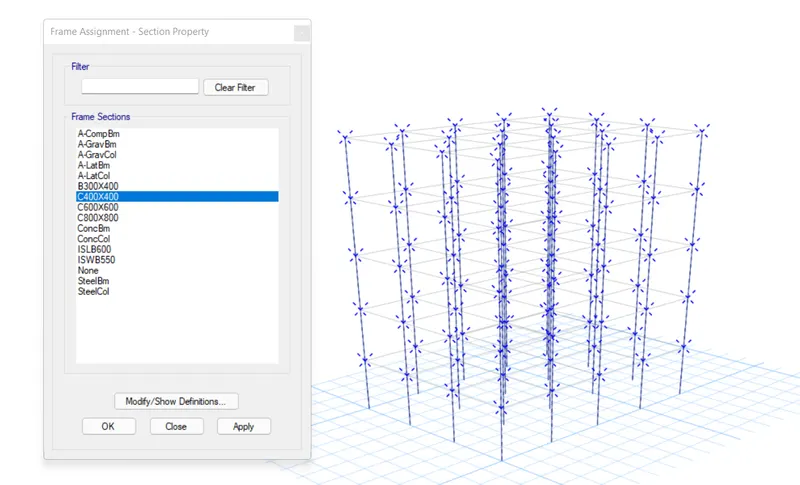
Columns for top 5 stories: C400X400
Columns for middle 10 stories: C600x600
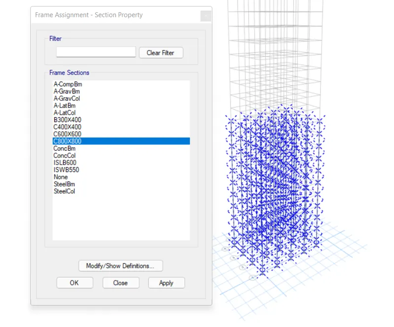
Columns for bottom 10 stories: C800x800
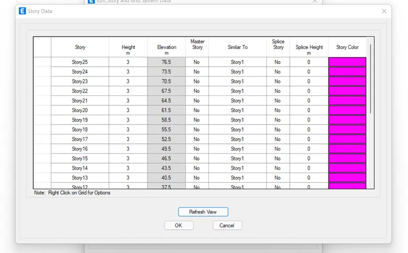
- Edit the Story Data and Add up 15 New Stories
- View Settings
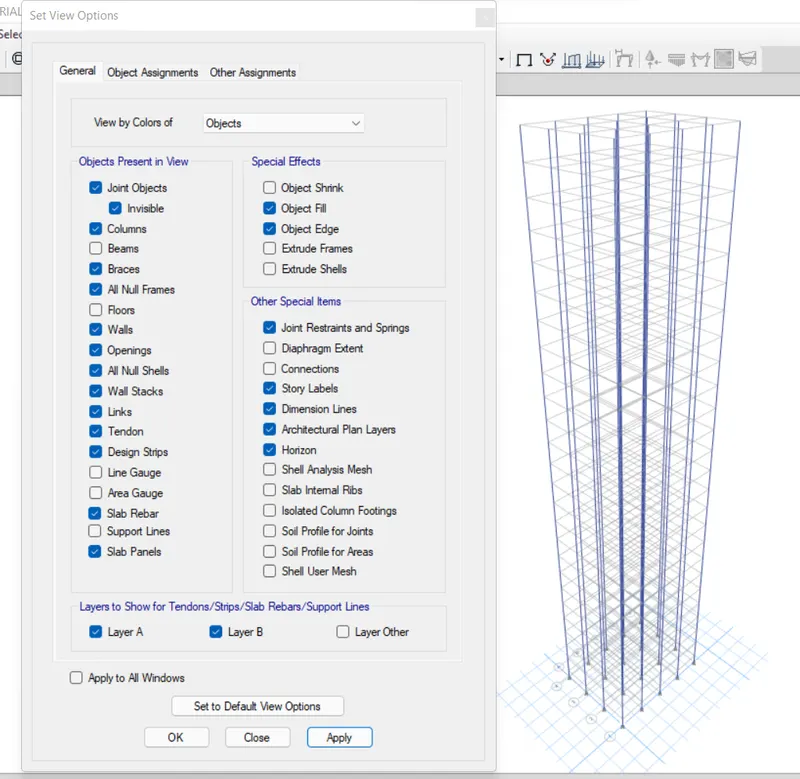
- Set Building Limit from 1-10
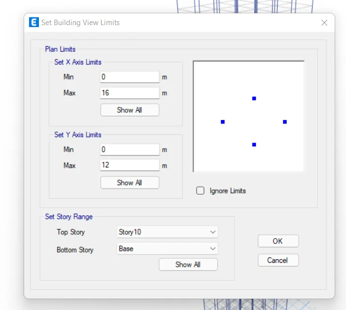
- Select all the Columns and Assign C800x800 Section
- Set Building Limit 11-20
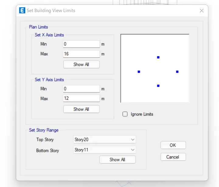
- Select all the Columns and Assign C600x600 Section
- Set Building Limit 20-25
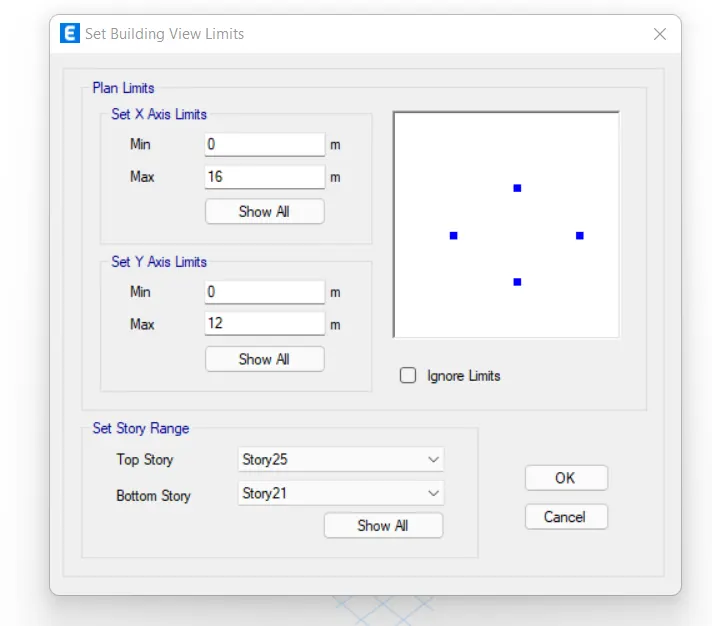
- Select all the Columns and Assign C400x400
- Run the Analysis
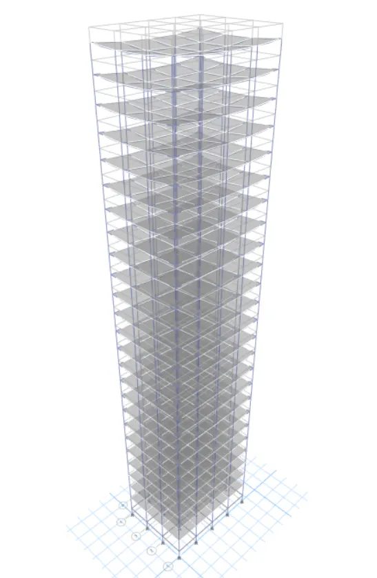
- Modal Response for Building G
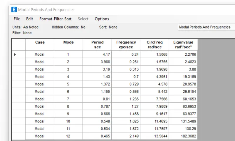
8. BUILDING "H" (G+25)
Consistent column size throughout the building: C800X800
PROCEDURE:
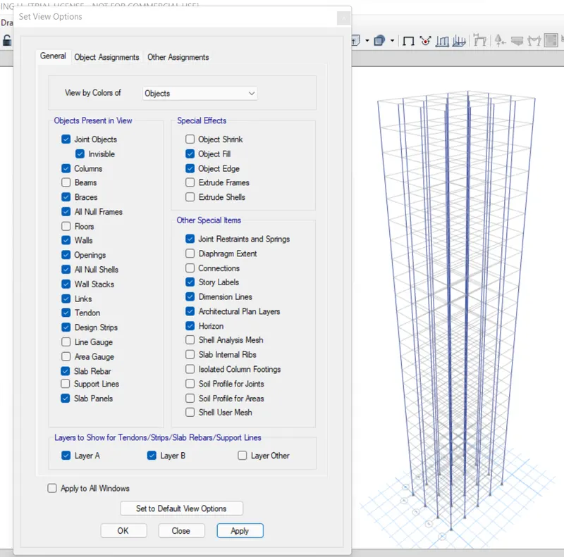
- View Settings to Hide Beams and Floors
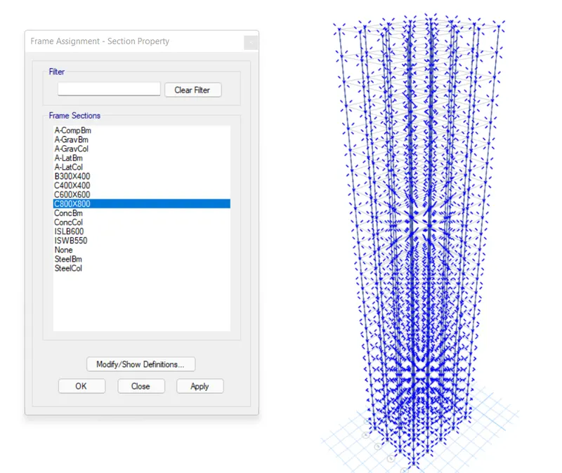
- Select All the Columns and Assign C800x800 Section
- Run the Analysis
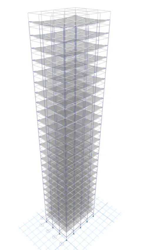
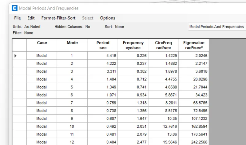
- Modal Response for Building H
9. BUILDING "J" (G+25)
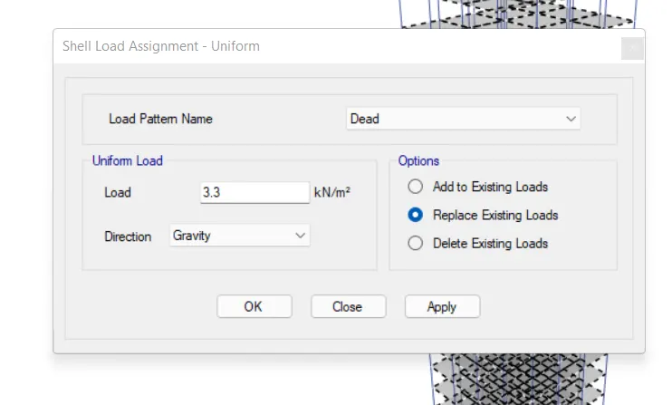
10% increment in the imposed loads
PROCEDURE:
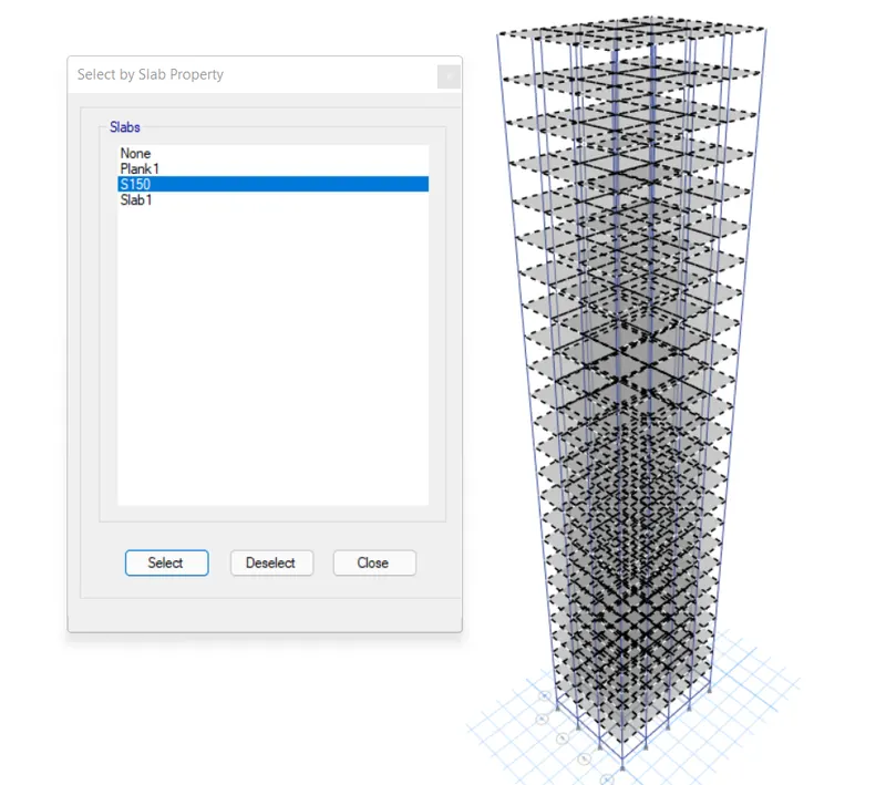
- Select the S150 Slab Section
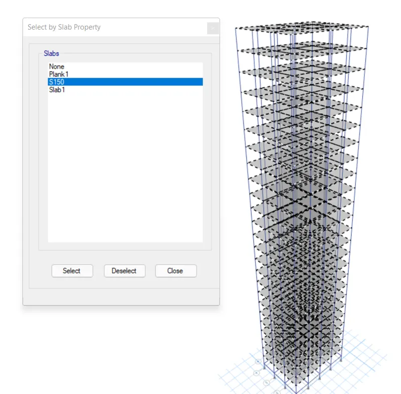
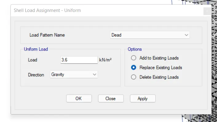
- Go to Assign>Shell loads>Uniform>increase it by 10%
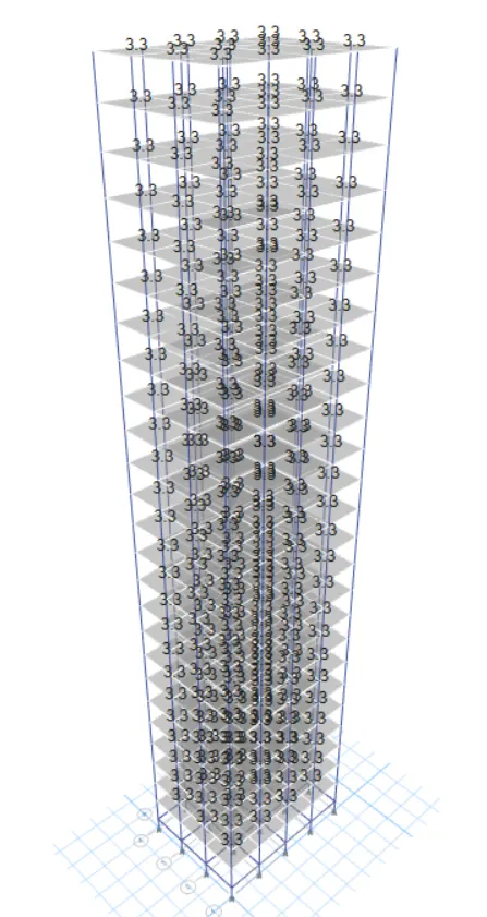
- Run the Analysis
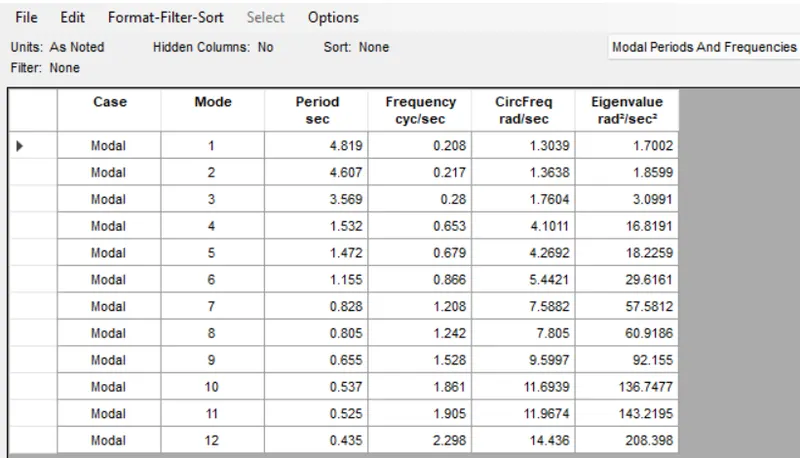
- Modal Response for Building J
10. BUILDING "K" (G+25)
20% increment in the imposed loads
PROCEDURE:
For this model, we can follow the exact procedure as we did for building j. However this time, we need to increase the live load by 20% as opposed to 10%. So, the stepwise procedure has been listed down below:
- Select the S150 Slab section
- Assign 3.6 KN/m^2 distributed shell load for a 20% increase
- Run the Analysis
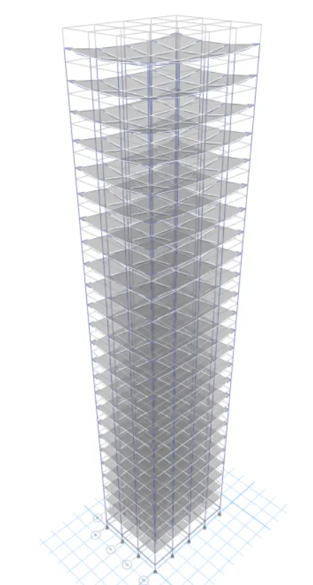
- Modal Response for Building K
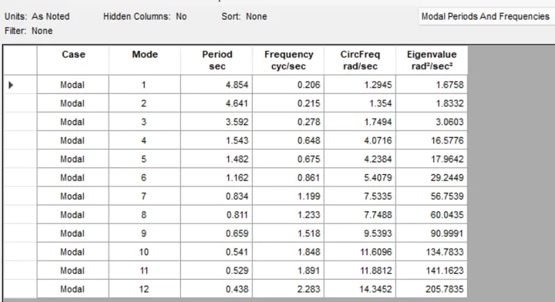
COMPARATIVE ANALYSIS OF BUILDING PROPERTIES BASED ON THEIR STRUCTURAL OUTPUTS
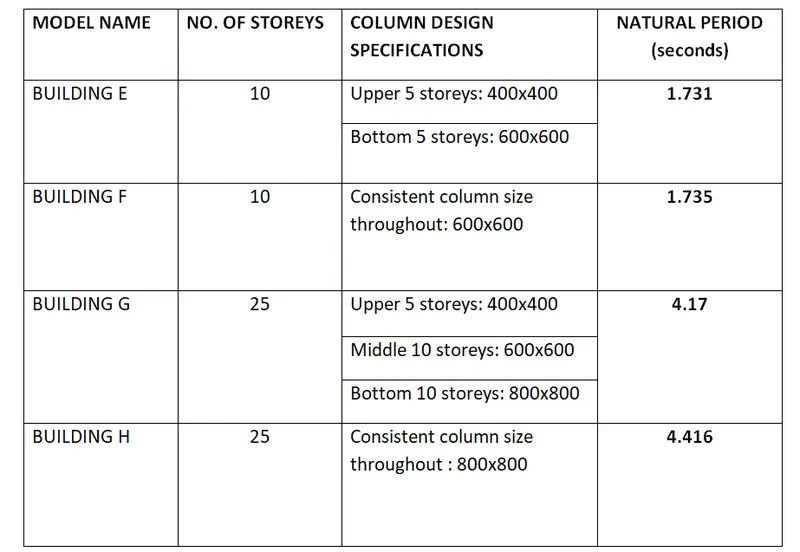
- Effect of stiffness on T: Compare fundamental natural periods of buildings E & F as well as G & H. Why is there a marginal or significant difference in the fundamental natural periods?
Comparative Table
Conclusion:
For buildings E and F, varying column designs arenot significant as there are only five stories. However, we can see that for buildings G and H, the consistent column size throughout the structure causes a more natural period. Therefore, it can be concluded that providing larger columns at the base and then reducing the size on top floors helps control the natural period 'T' for tall buildings.
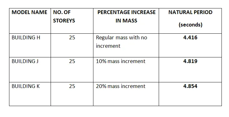
- Effect of mass on T: Compare fundamental natural periods of buildings H, J and K. Have the buildings become more flexible or stiff due to change in mass?
Comparative Table
Conclusion:
As seen from the table, the natural period for the tall buildings is directly proportional to the imposed mass of the building.
- Effect of Building Height on T: How do the fundamental natural periods of Buildings A, B, F, and H change with a change in building height?
Comparative Table
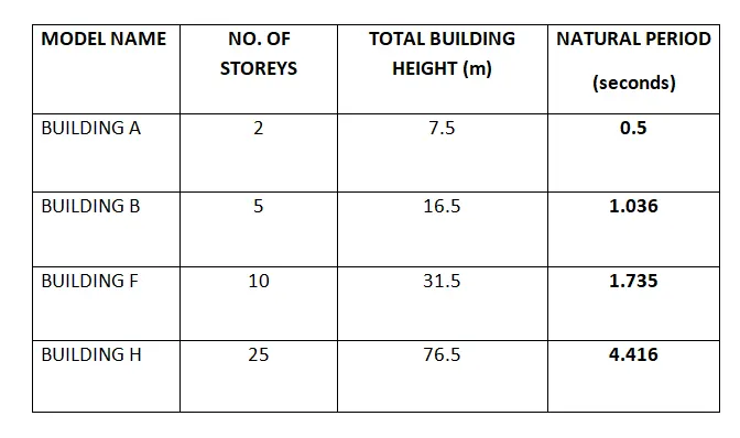
Conclusion:
As indicated in the above table, the natural period 'T' is also directly proportional to the building height.