Project 1_Comparative study of different storey buildings for Seismic forces
AIM: TO MODEL AND ANALYZE MULTIPLE BUILDINGS WITH DIFFERENT FLOOR LEVELS AND DESIGN PARAMETERS USING ETABS SOFTWARE AND COMPARE THE RESULTS TO UNDERSTAND THEIR OVERALL SEISMIC BEHAVIOUR.
INTRODUCTION:
The structural configuration of the building plays a major role in determining the overall response during an earthquake.different building geometries behave differently when induced by the same seismic forces. hence , it is very important to properly understand the response of building related to their structural configurations for a saferbdesign approach.
PHASE ONE: Modeling the buildings and generating their respective structural outputs usings ETABS
There are total 10 buildings included in this project to achieve a more comprehensive conclusion. the buildings are listed in alphabetical order starting from A and ending ar K. A complete stepwise procedure to model all the buildings and generate their respective structural outputs is discussed in detail as follows.
1. BUILDING - A (G+2)
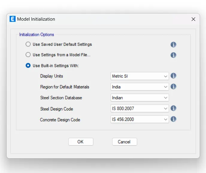
- open ETABS and set up the model
- once the software is up and running , click on the new model option.
- set up the codes and units to be used in your project.
-thus, do the needful settinga and clock ok to start modeling the first building in the project.
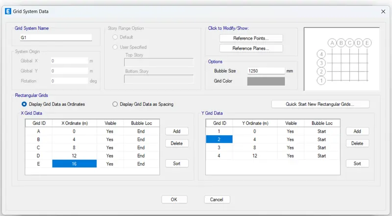
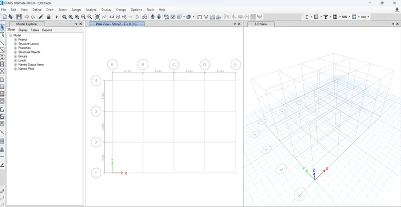
- Sting up the grid data
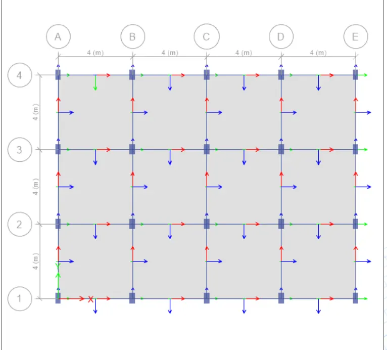
- We have set up a 4 x 3 bay grid with 4m center to cener spacing in beeetween.
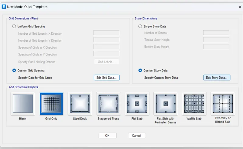
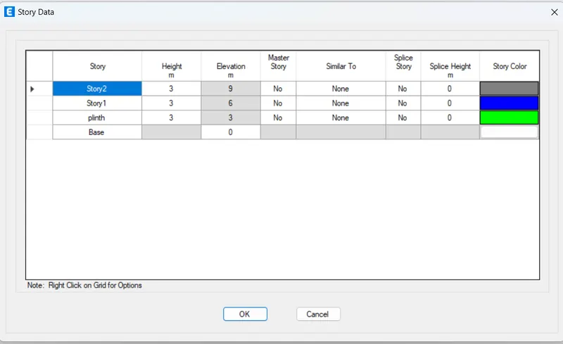
- Fixing the story data
- similar to what we did while setting up the grids, click on the custom story data option,
- Thus , we have arranged for G+2 building with 1.5m plinth height from the base and floor height is 4m.
- also you need to fix a master and all other remainng floors are similar story.
- Defining the material properties
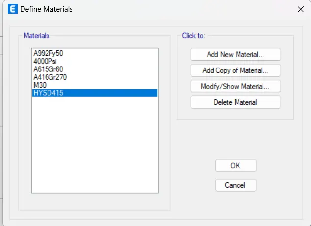
- it is important to set details of the materils you are going to use for the project in etabs .
- and for our model, we have to use the M30 grade concrete and Fe 415 HYSD steel as per the specifications.
- However , sonce we have already specified the indian standerd codes of practices , the M30 concrete and 450 steel is added by defualt into the project.
- Defining section properties
- we are using rectangular concrete sections for all the structural elements like beams , columns and slabs.
- so we need to define that in ETABS software so that it allows us to use these sections respectedly thoughout the project.
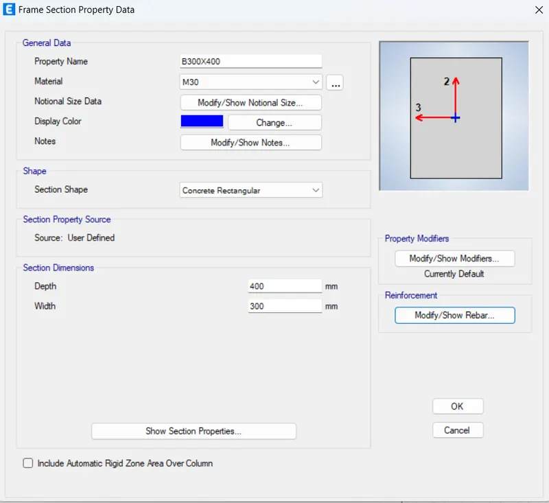
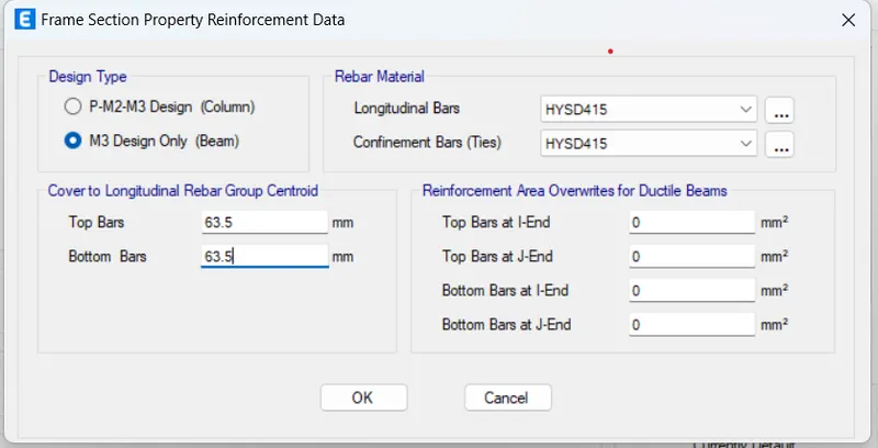
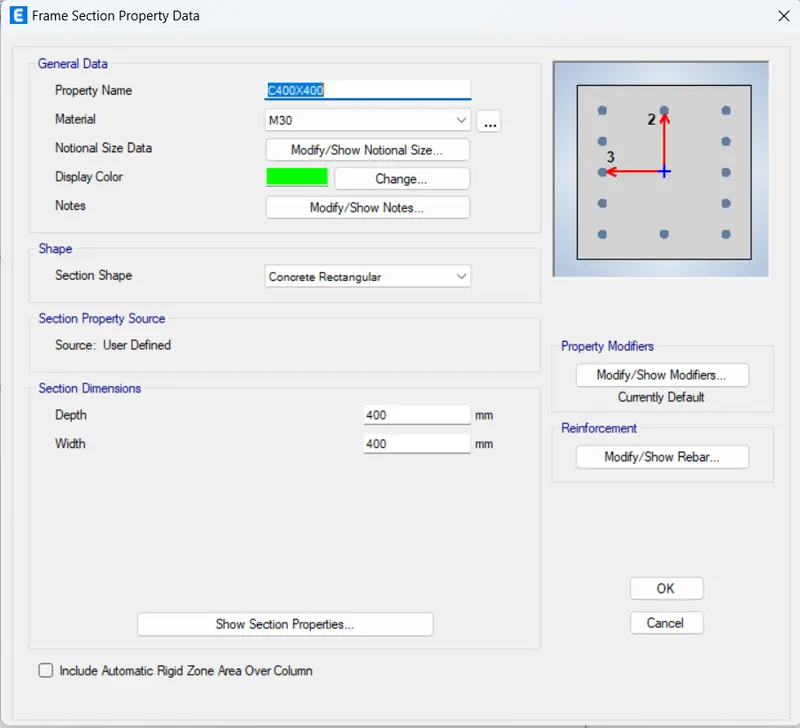
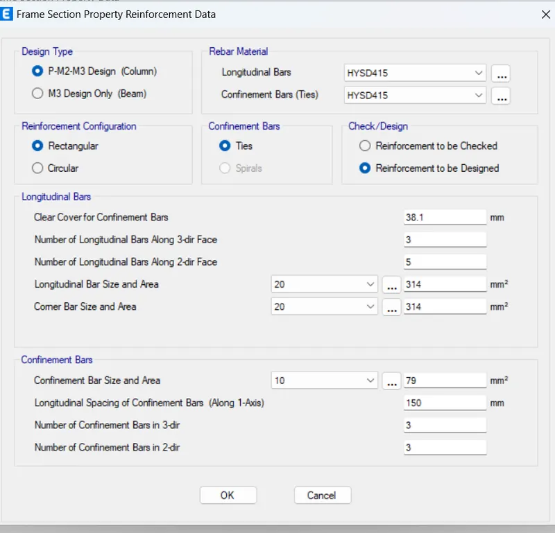
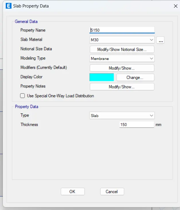
- and to do so, go to define section, properties, frame section, concrete rectangular.
- then we create a column and beam and slab dimension and create sections.
B 300x400
C400X400
S150
- Execute the modeling
- Now that we have defined ecerything from matrials to beams, columns, and slabs to be needed and draw each structural element as per the specifications.
-as the name suggest, you can draw all the beams , column, and floors with the help of this tool.
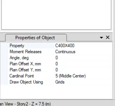
Quick draw columns
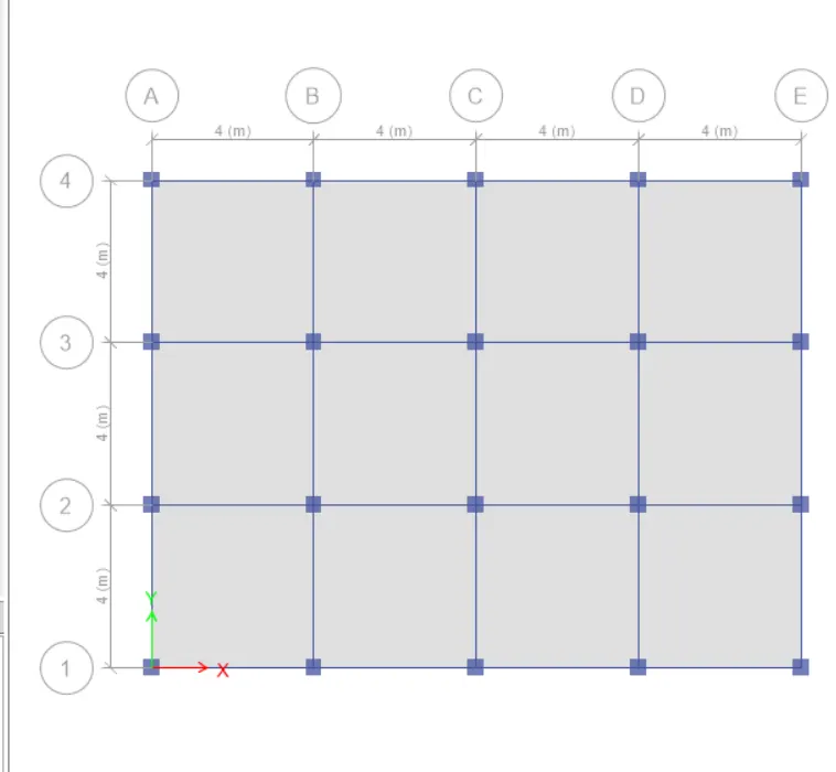
Quick draw beams:
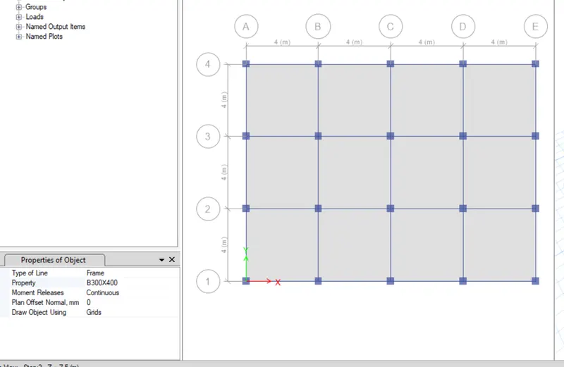
Quick draw floors:
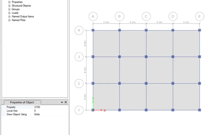
omplete model in 3D:
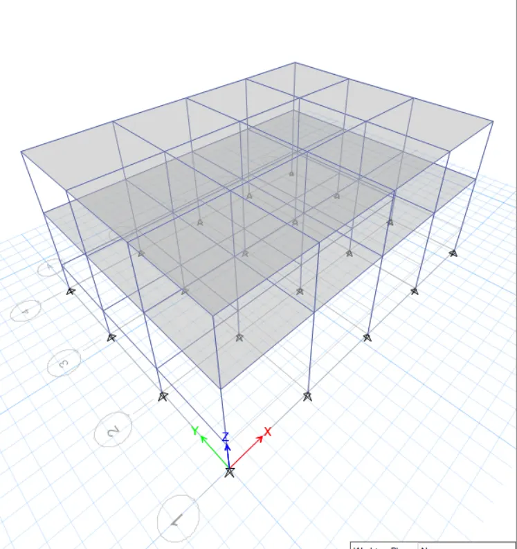
- Define the load patterns
- After completing the model, now we need to list down the types of loads that are expected on the structure during its service period.
- here, you can add all the loads and for our project, we are having the dead load, super dead load ( Brick wall load), Live load, and the Earthquake load in X and Y Directions.
- Also you need to define the mass source by adding 100% of dead load and super dead load as wall as 25% of the imposed or live load.
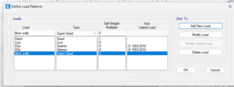
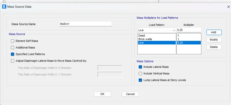
- Generate load combinations
- Go to define load combinations default combinations check the convertible option.
- A list of load combinations will appear which you can look at and modify anytime during the project if needed.
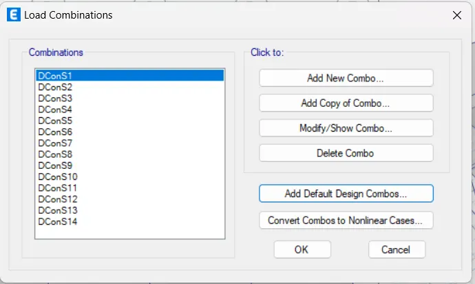
- Assign loads to the structural members
- you can select a particular structural member from the model and assign it the load that is imposed on it.
- for example, select the beam and assign a udl of super dead load due to the brick walls resting upon it.
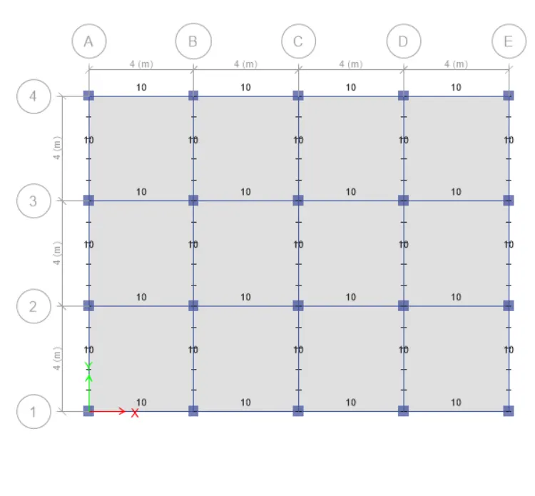
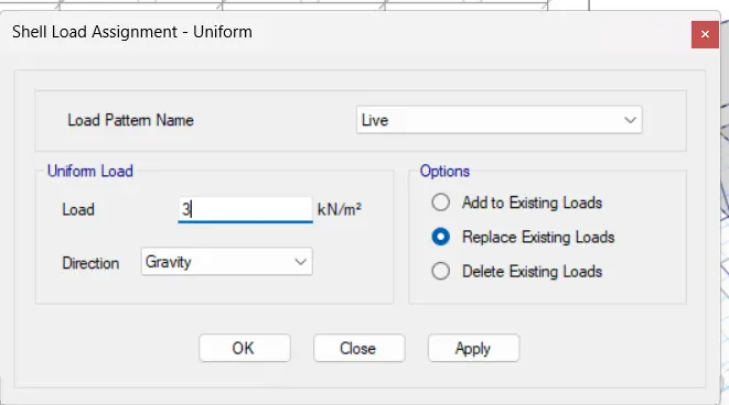
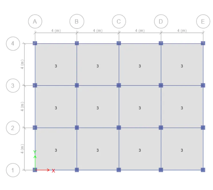
- Thus, a similar technique is used and the loads on beams and slabs are assigned as follows.
10KN/m Brick wall load on Beams
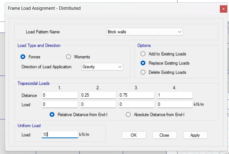
3 KN/ M^2 Live load on slabs
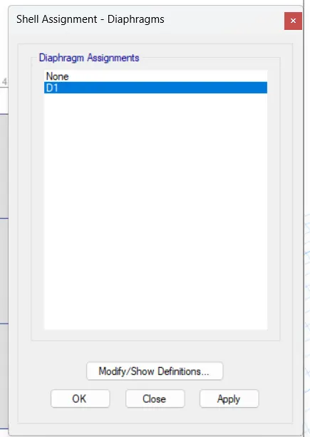
- Assign the floor diaphragm
- Select the S150 slab section from the select option.
- Go to assign shell diaphrigm
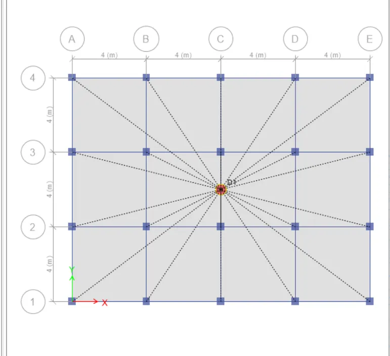
- Save the model and run analysis
- Now that everything with regards to our first model is complete, we can proceed to run the analysis for this bulding.
- But we'll have to first save our project before running the analysis so do it at the preferred location within your system.
-Then you can simply press F5 on your keyboard or click on the arrowhead available on the ETABS screen to run the analysis for the current model.
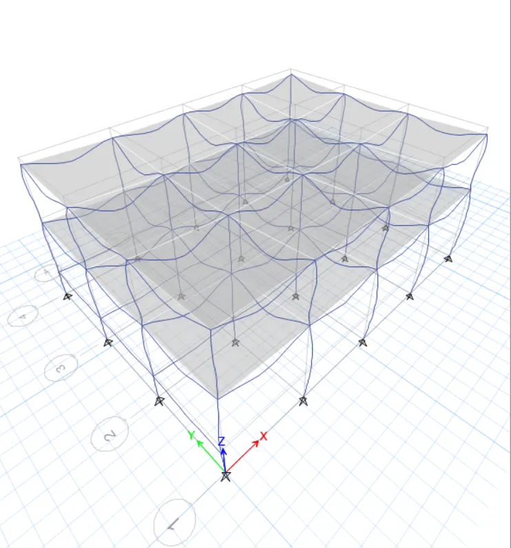
Model response for Building A
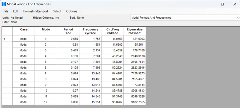
2. BUILDING "B" (G+5)
now to model building B, we need not create a new ETABS file from scratch. Rather we will save a copy of a A file and do the Alternate file For Building B.
- Make a copy by save as
The model is set for changes as per the requirements of building B
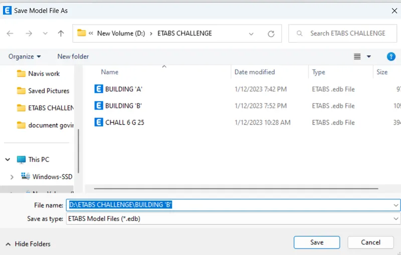
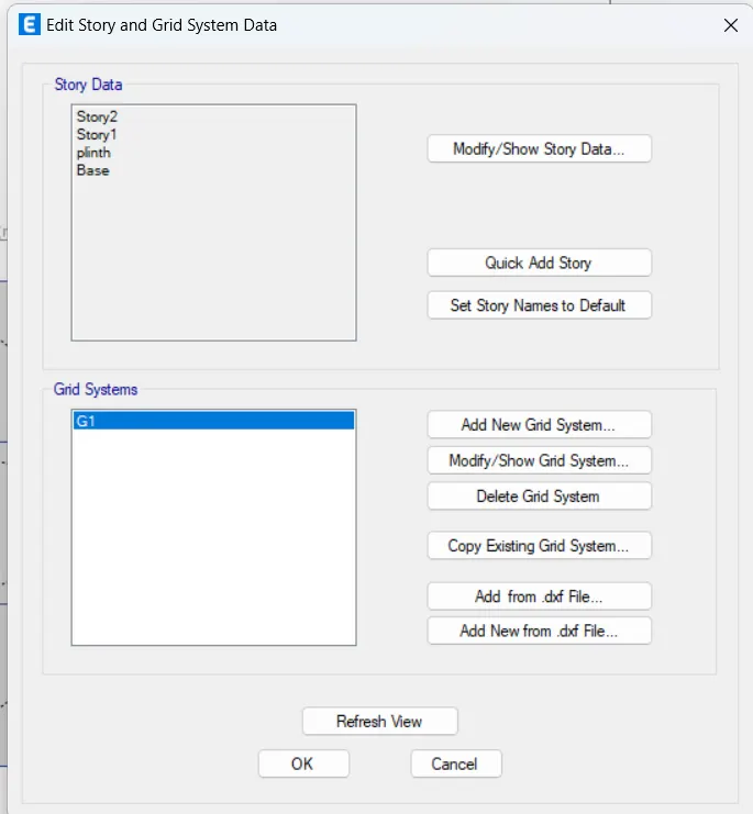
- Edit story data
- From the new file go to edit story and drid data.
- click on the modifiy story data option.
- Then right click on the top story and select the add story option.
- in our case ,we need to add 3 more floors to convert our 2 story building into a 5 story one.
- also, make sure to make each story similar to the master story created in model A.
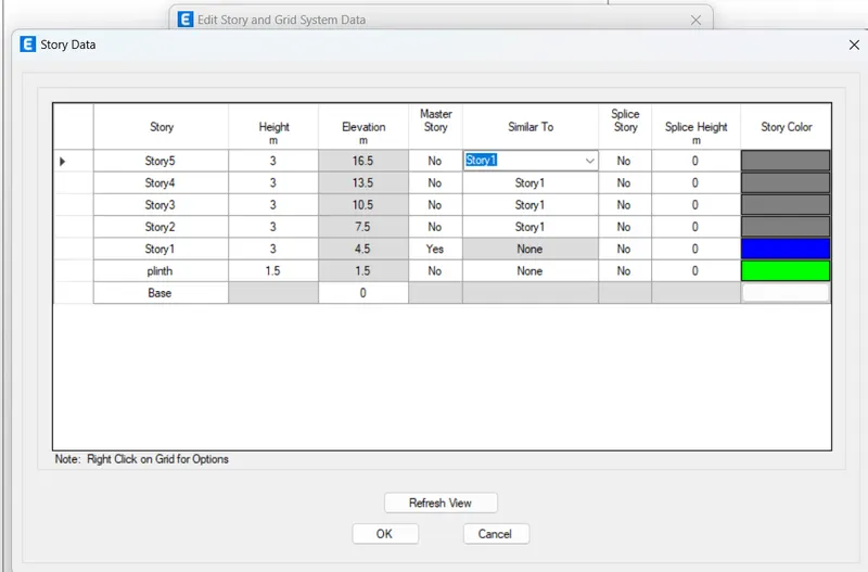
CONVERTED 5 STORY MODEL
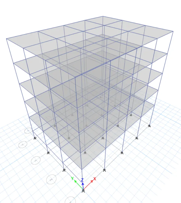
- Check the model before running analysis
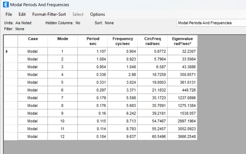
- now that our model is ready we need to check for two to three things before running the analysis and noting the modal period.
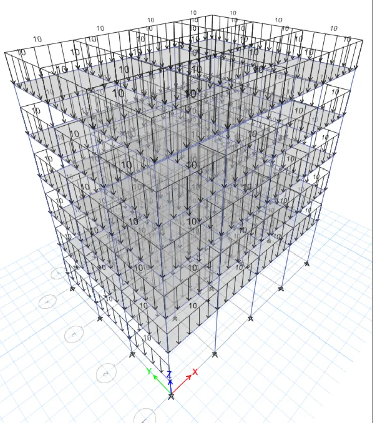
- the first check is for the load assignment.
- From the bottom ribbon in ETABS, go the show frame and shell loads one at a time.
-- this way the model will show if the corresponding load has been assigned to the new model or not.
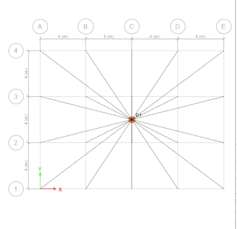
- you can check it by going to the view settings option and checking the diaphragm like we did for the first model.
Check for shell loads
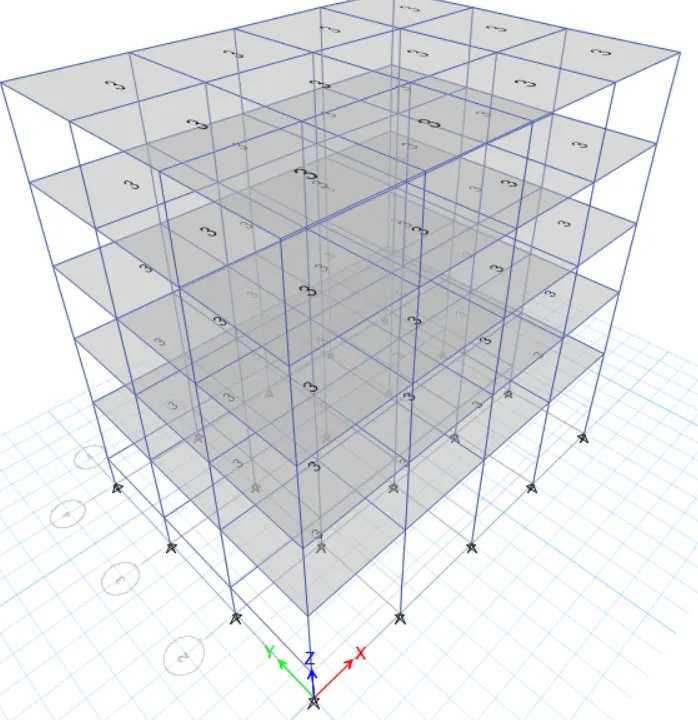
checks for the frame loads
checks for the diaphragm
- Run the analysis
- Now that all the checks have been made and the structure is ok we can run the analysis.
- and to do that simply press the F5 button on your keyboard or click on the arrowhead available at the bottom ribbon in ETABS.
- It will take a few seconds and the deflected shape of the building will appear indicating that the analysis has been completed.
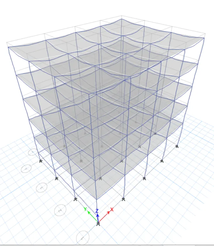
Model response for building B
3.BUILDING 'C' (G+5 with column orientation in X- direction)
- the story and grid data for building c will remain still. however, we need to change the column size and orient the same in the X direction. so, the complete stepwise procedure for the same is discussed in detail below.
- Create a copy model by save as
- like we did for building B, now do it for building c thriugh building B.
- Choose the appropriate location and save the file as building c.
- Now , the model is set to be edited as needed.
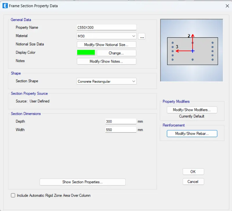
- Edit the column size and orientation
- To edit the column section go to define, section properties, frame section.
- Now select the previosly created column for building A and B.
- Rename the column as needed Which in our case is 550X300.
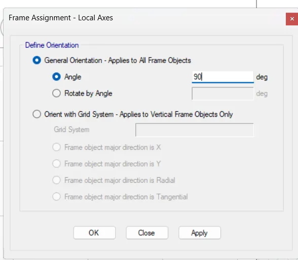
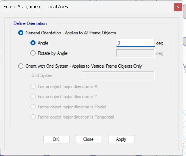
- Now we need to orient the 550mm in the X - direction. so, select the column section then go to assign , local axis , rotate 90 degrees.
-This way , all the columns shall be oriented in the X- direction meaning 550mm laying down in the x- direction.
Required column section
- Checks before running the analysis
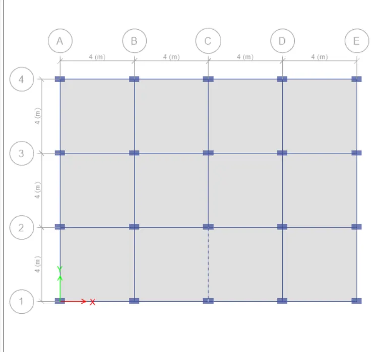
- Like we did for building B checks for the frame and shell loads are to be made.
- also, make sure the floor diaphragm has also been assigned before going ahead with the analysis.
checks for the Fram loads
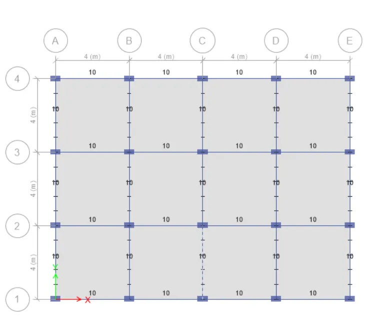
checks for the shell loads
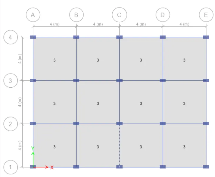
Diaphragm check
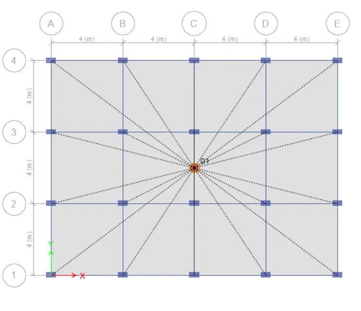
- Run the analysis
- Hit the F5 button on your keyboard and ETABS will automatically run the analysis for you.
- you can display the modal table when the analysis is complete the deflected shape of the model is visible on your screen.
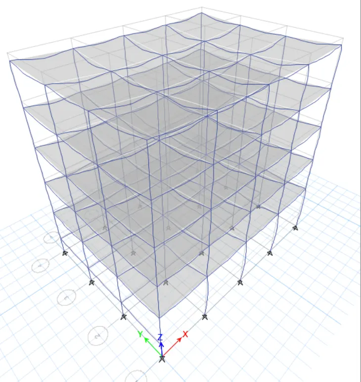
Model response for Building C
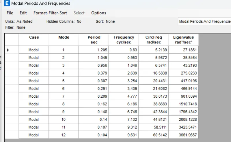
4 . BUILDING 'D' (G+5 with column orientation in Y- direction)
In this model, we dont need to alter anything other than the column orientation. the sizes of the column will remain the same however, we have to shift the column orientation from X to Y direction. so follow the same prosedure as we did for the previos model and save the c file into the Dfile
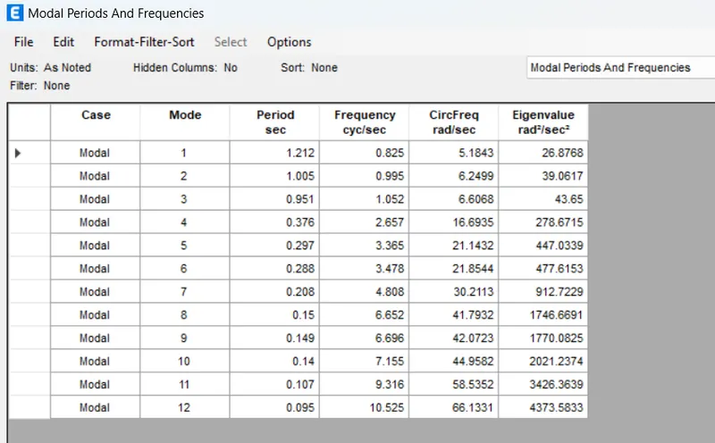
So, as explained above, the model was executed for building D and the natural period was noted as inserted below.
- select the column section and bring the orientation back to zero
(The detailed procedure to do it has already discussed for the previous model)
Required column section
Run the analysis
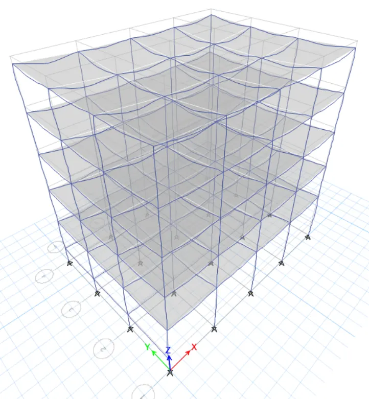
Model response for Building D
5. BUILDING 'E' (G+10)
column sizes for top 5 storeys: 400X400
column sizes for bottom 5 storeys: 600X600
PROCEDURE:
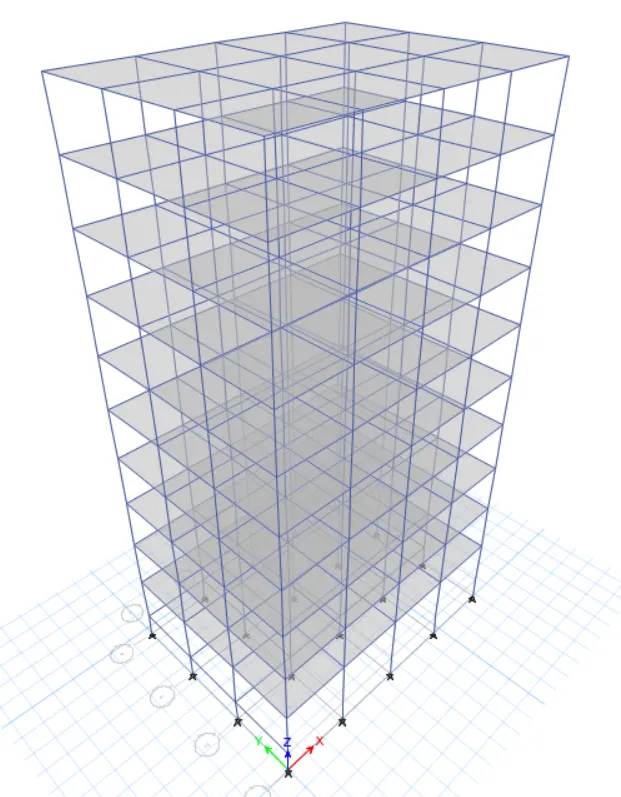
In this model, we need to assign add up 5 more storeys to our model. in addition, we also need to assign different floors. and to do that, we'll first save the etabs file for building D as a new model building E.so the stepwise procedure to create new column and locate them on require floors is explained below.
- Add up 5 new stories and set the model for building E
- change the view settings of the model
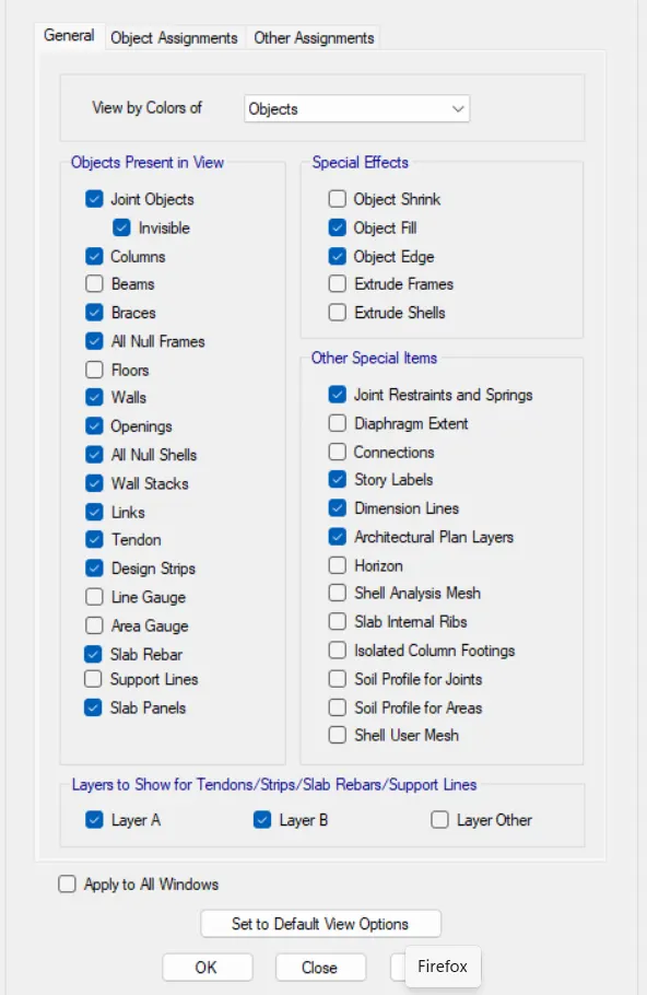
- There is an option in ETABS that allows users to adjust the model and view the only objects that are needed to be worked on currently.
- The tool is called view option settings it is easily accessible from the front tool ribbon f ETABS.
- So, you can go to view option settings and uncheck the structural members that you want to hide currently for modeling purposes.
- since we need to assign different column sizes in our model, we don't need to view beams and slabs currently so, we go to the tool and uncheck beams and floors in order to make the only columns visible for editing purposes.
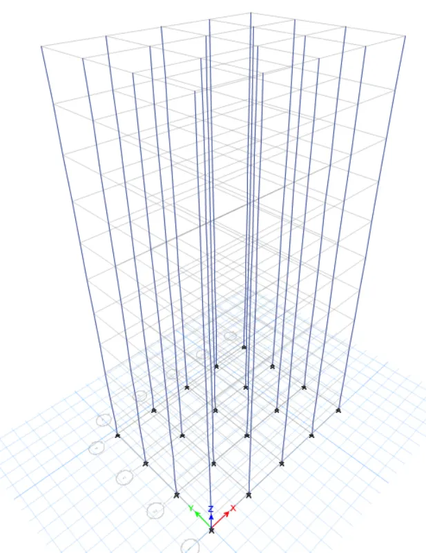
- Set the building limit , select the column and assign them the required section.
- now , since we need different columns for top 5 story and different columns for the bottom five .
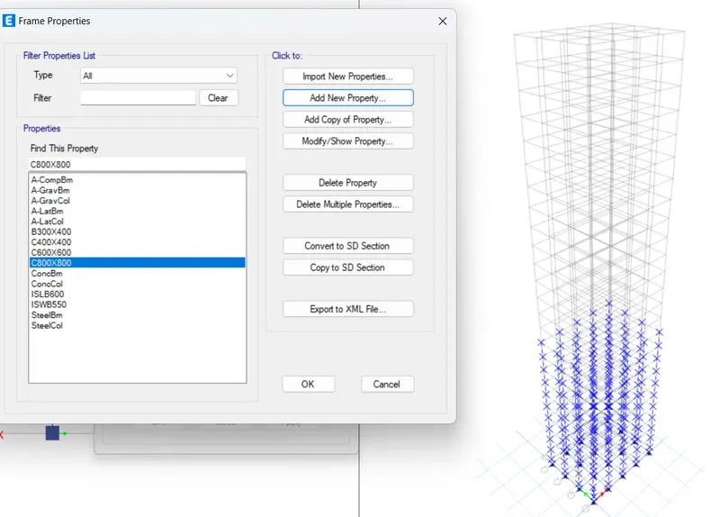
- first we go to first 10 story to set assign the column c 600x600.
C600x600
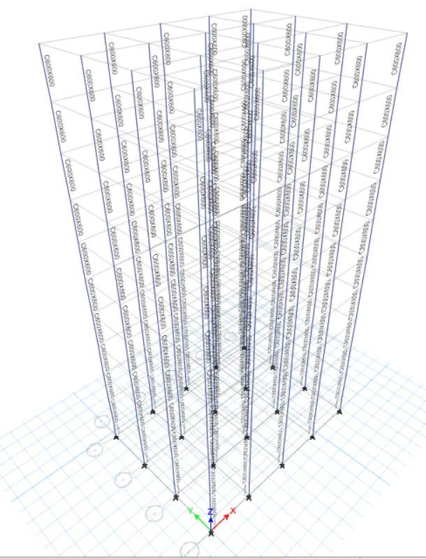
- Hence, first set the limit to top 5 storey select all the column and assign to requred column.
- Building limits for top 5 stories
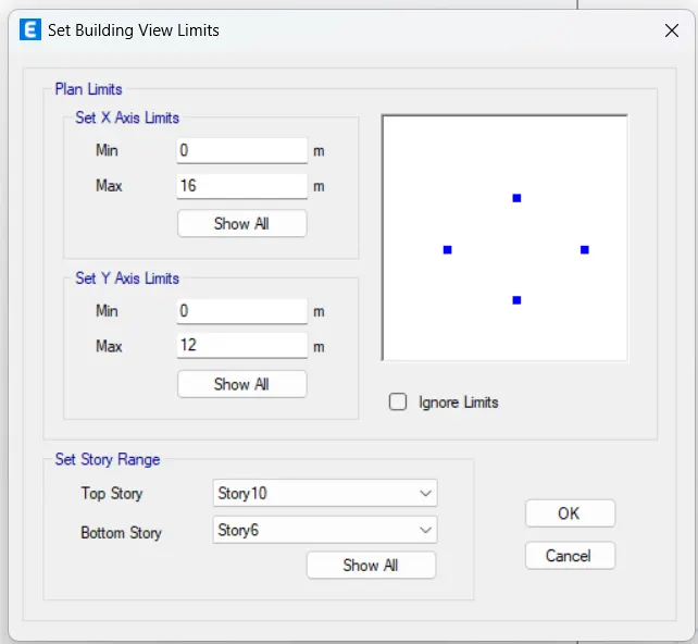
- Assign c600x600
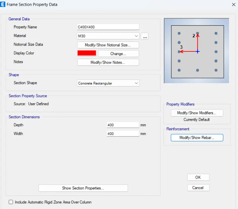
- Select all column and assign them c 400X400 section
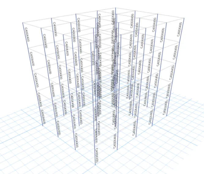
- Model after assigning different columns for diffrent floors
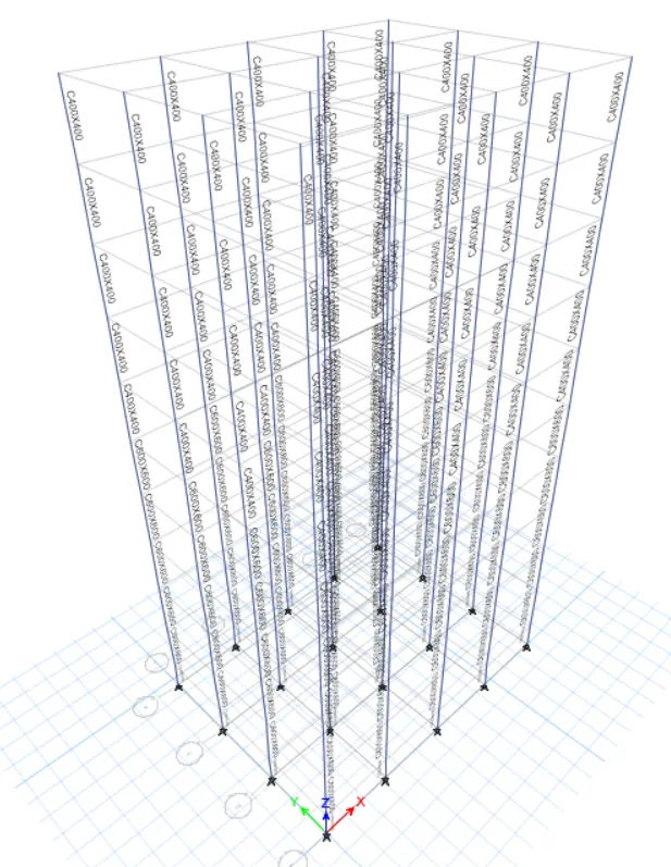
- Run the analysis
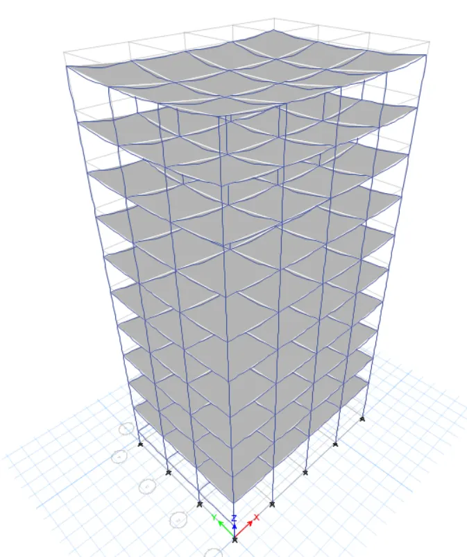
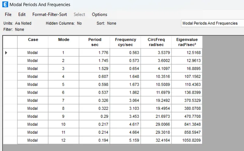
- Model response for building E
6. BUILDING 'F' (G+10)
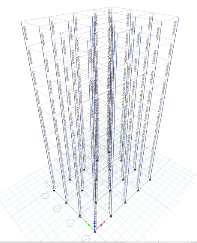
Consistent column size throughout the structure: C600X600
PROCEDURE:
This building has the same columns for the entire structure.
- adjust view option settings
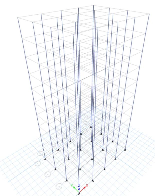
- Select all the columns and assign C600X600
- Model response for building F
7. Building G(G+25)
- columns for top 5 stories: C400X400
- Columns for middle 10 stories: C600X600
- Columns for bottom 10 stories : C800X800
PROCEDURE:
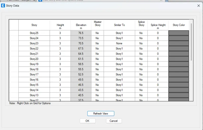
For this model, we need to add 15 new stories and assign different column sizes on different floors. we can follow the exact procedure that has already been explained for the privious project to create this model by editing building F.
- Edit the story data and add up 15 new stories
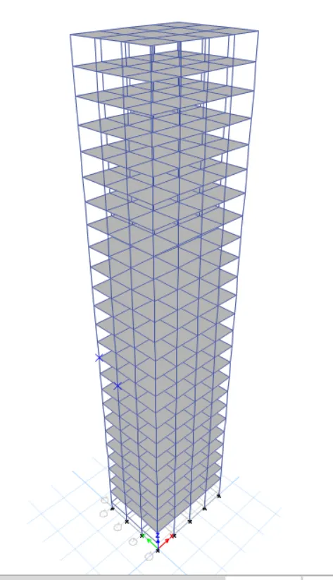
- VIEW SETTING
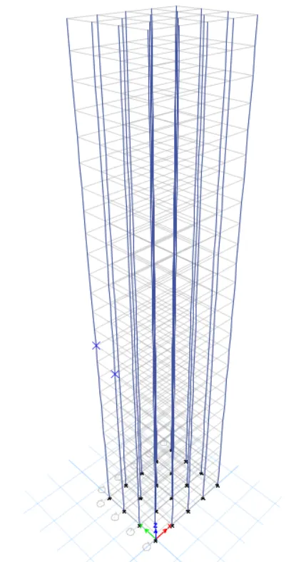
- Set building limit from 1-10
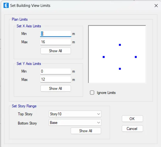
- Select all the columns and assign C800X800 Section
- Set building limit 11-20
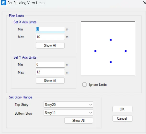
- Select all the columns and assign C600X600
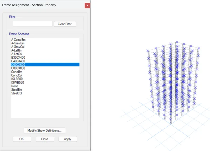
- Set Building limit 20-25
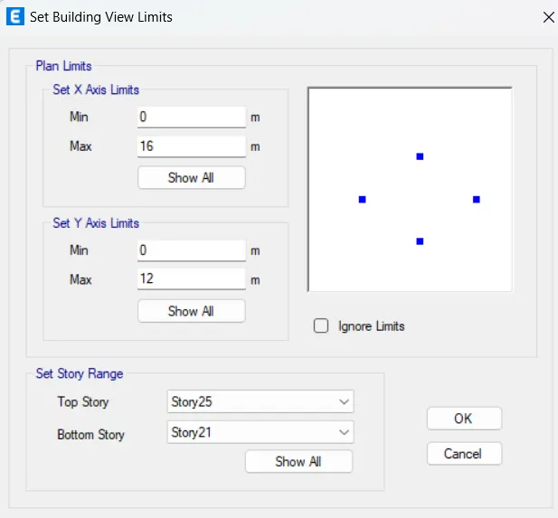
- Select all the columns and assign C400X400
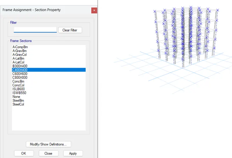
- Run the analysis
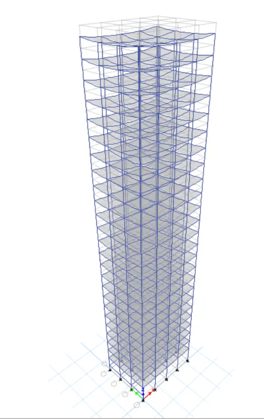
- Model Response for building G
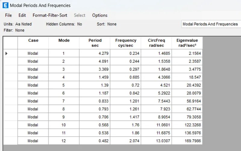
8. Building 'H' (G+25)
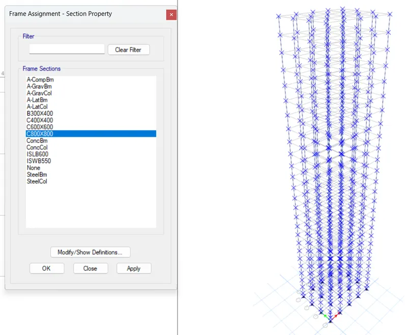
- consistetn column size throughout the building C800X800
- view settings to hide beams and floors
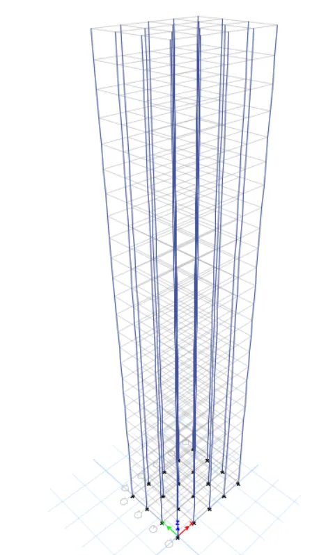
- Select all the columns and assign C800X800 section
- Run the analysis
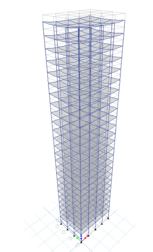
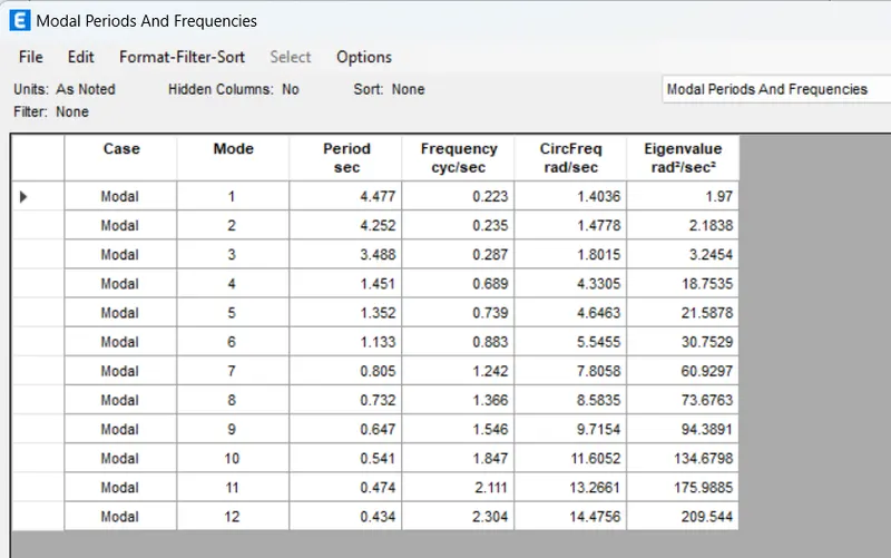
- Model response for the Building H
9. BUILDING 'J' (G+25)
10% increase in the imposed loads
Procedure
Building J is the exact copy of the model H and we dont need to alter anything related to the modeling. we need to increase the imposed load on the building by 10% which is assigned as 3kn/m^2an all slabs of the building
- Select the S150 Slab section
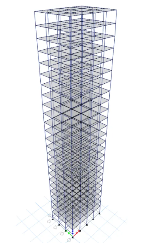
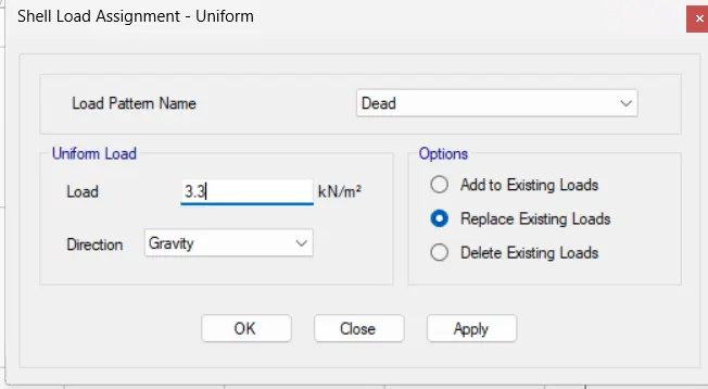
- Go to assign shell , loads , uniform, increase it by 10%
- We have assign a 3 kn/m2 imposed load on all slabs for all of our previous buildings.
- so, we need to increase that by 10% meaning we need to replace the existing imposed load with 3.3 kn/m^2
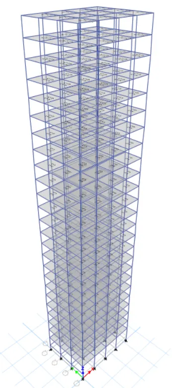
- Run the analysis
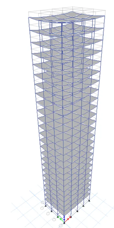
- Model response for Building J
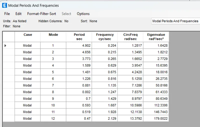
10. BUILDING 'K' (G+25)
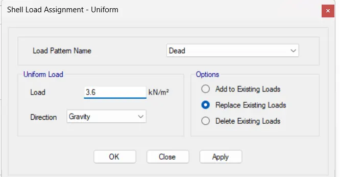
20% increase in the imposed loads
PROCEDURE:
For this model, we can follow the exact procedure as we did for building J. we need to increase the live oad by 20% as opposed to 10%. so, the stepwise procedure has been listed down below.
- Select the S150 slab section
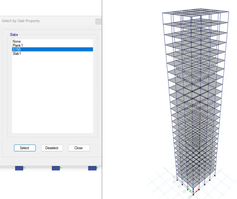
- Assign 3.6KN/M2 distributed shell load for 20% increase
- Run the analysis
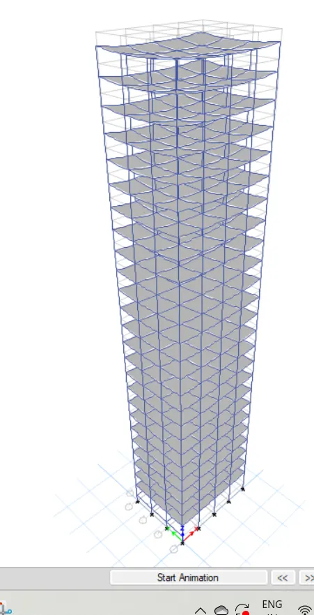
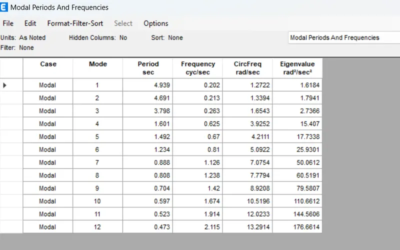
- Modal response for Building K
PHASE ll : COMPARATIVE ANALYSIS OF BUILDING PROPERTIES BASED ON THEIR STRUCTURAL OUTPUTS
As we have completed the modeling and analysis of diffrent story building in the previous phase of this project, now now we are going to compare those results and try to understand the change in behaviour of buildings based on their structural geometries.
So, a comprehensive comparative analysis of structural properties of different story buildings is executed in the below sections on the basis of various criteria such as stiffness, mass, building height , etc.
- Effect of stiffness on T: Compare fundamental natural periods of buildings E& H. Why is there a marginal or significant difference in the fundamental natural periods?
Comparative Table
| MODEL NAME | NO. OF STOREIS |
COLUMN DESIGN SPECIFICATION |
NATURAL PERIOD(SEC.) |
| Building E | 10 |
upper 5 stories 400X400 Bottom 5 Stories 600X600 |
1.776 |
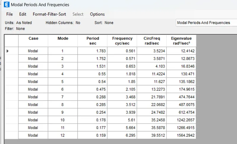
| Building F | 10 | Consistent column size through 600X600 | 1.783 |
| Building G | 25 |
Upper 5 stories 400X400 middle 5 Stories 600X600 Bottom 5 Stories 800X800 |
4.279 |
| Building H | 25 | Consistent column size through 600X600 | 4.477 |
Conclusion:
For building E and F, varying column design doesn't make a big difference as there are only five storeis. However, we can see that for building G and H, The consistent column size Throughout the structure causes a more natural period. Therefor, it can be concluded that providing larger columns at the base and then reduving the size on top floors helps control the natural period T for tall Buildings.
- Effect of mass on T: Compare fundamental natural periods of buildings H, J and K. Have the buildings become more flexible or stiff due to change in mass?
| MODEL NAME | NO. OF STORIES | PERCENTAGE INCRESE IN MASS | NATURAL PERIOS (SEC) |
| building H | 25 | Regular mass with no increment | 4.477 |
| Building J | 25 | 10% mass increment | 4.902 |
| Building K | 25 | 20% mass increment | 4.939 |
Conclusion:
As seen from the table, the natural period for the tall buildings is directly propertional to the imposed mas of the building.
- Effect of column orientation on T: how do the fundamental natural periods of buildings B,C and d Change with a change in column orientation?
| MODEL NAME | NO.OF STORIES | COLUMN ORIENTATION |
MAXIMUM STORY DRIFT (MM) Due to EQx Due to EQy |
| Building B | 5 | equal in both direction | 5.45 5.77 |
| Building C | 5 | X-direction | 5.73 5.73 |
| Building D | 5 | Y- direction | 6.39 6.45 |
Conclusion:
When the column cross section in square , there is not much different between the lateral displacement in both the orthogonal direction. However, when you orient the column in a particular direction be it X ro Y , the lateral displacement in that particular direction will be less than other direction which has a lesser column length.
- Effect of Flexural Stiffness of Structural Elements on mode shapes: Compare fundamental mode shape of Building B in two situations when the flexural stiffness of beams relative to that of adjoining columns is very small versus when it is large.
| Model name | Flaxural stiffness of beams | Natural period (sec.) |
| Building B | 10% | 2.73 |
| Building B | 100% | 1.107 |
Conclusion:
It is pretty obvious that if you decrease the flexural stiffness of beams, the overall flexural strength of the beam is also going to reduce, and consequently, the fundamental natural period will shoot up.
- Effect of Axial Stiffness of Vertical Members on mode shapes: Compare the fundamental mode shape of Building H in two situations when the axial cross-sectional area of columns is very small versus when it is large.
| Model Name | Axial stiffness of columns | Natural period |
| Building H | 10% | 6.22 |
| Building H | 100% | 4.47 |
Conclusion:
As the axial stiffness of columns decreases, the fundamental natural period of the building increases regardless of its structural geometry.