Project 1 : CFD Meshing for Tesla Cyber Truck
CFD Meshing for Tesla Cyber Truck
Aim:
For the given model of tesla's Cyber truck, check and solve all geometrical errors and Assign appropriate PIDs. Perform meshing with the suitable Target length and element Quality criteria and also create a wind tunnel and perform volumetric mesh.
OBJECTIVE- For the given Tesla Cybertruck model , check and solve all geometrical errors and Assign appropriate PIDs. Perform meshing with the suitable Target length and element Quality criteria.
Introduction :
ANSA :
- ANSA is a Computer-aided engineering tool for Finite Element Analysis and CFD Analysis widely used in the automotive industry. It is developed by BETA CAE Systems. The software is distributed world wide by a number of BETA CAE Systems subsidiaries and business agents.
- ANSA maintains the association between CAD geometry and the FE mesh. This means that the FE meshes are better representations of their geometric parents. Also it is easy to maintain and update any changes in the geometry by simply reworking the updated area instead of recreating the FE from scratch.
- It carries several proprietary algorithms for meshing suitable for both CFD and structural models. ANSA was initially standing for 'Automatic net generation for structural analysis' , but the software has gone beyond that very quickly. ANSA has broadly six menus which are used to do various activities those are: TOPO MESH, VMESH ,DECK-SOLVER, MORPH ,HBLOCK.
Different type of modules in ANSA :
- TOPO - Set of tools for Geometry clean-up and for setting up of PIDs.
- MESH - Tools to generate Surface Mesh or 2D Mesh.
- VOLUME MESH - To generate solid or 3D Mesh.
- SOLVER DECKS - Tools based on different solvers such as ABAQUS, RADIOSS ,ANSYS etc.
- MORPH - Advanced tool to capture geometry more accurately while meshing.
Total procedure :
- For solving we follow the below procedure ,
- Import the CAD model.
- Identifying & cleanup of the topological / geometry errors .
- Geometry check-up.
- Setting-up of relevant PIDs.
- Defining the element size or length.
- Setting the mesh parameters , selection of meshing type and generating surface mesh of the CAD model .
- Resolving the errors in the surface mesh.
- Creating the wind tunnel for external flow CFD analysis and surface mesh of wind tunnel.
- Generating volumetric mesh.
- Let us start solving one by one by following above steps :
- Model:
- This is our raw geometry when we activated single cons we can see whole geometry covered in single cons, To avoid single cons do topo for whole geometry this will solve issue of single cons.
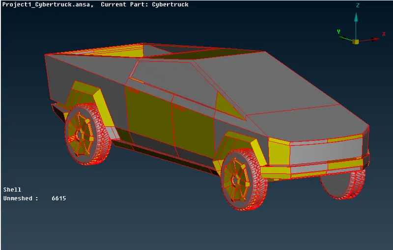
Fig:Tesla Cybertruck Initial car model
-Delete the right half of the model using the Delete option. It will be easy to operate on the left half of the model.
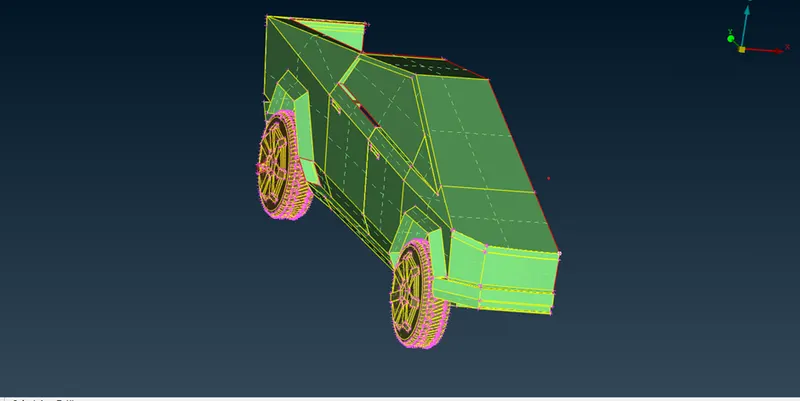
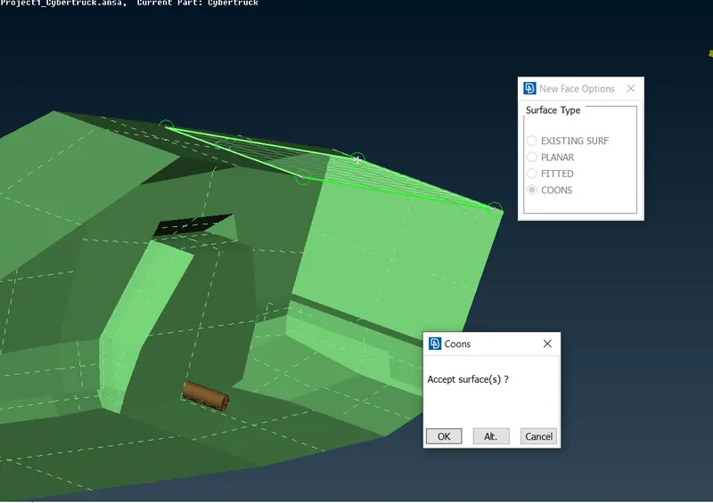
-There are a few missing surfaces in the model. Create new faces using the New option in the Face module.
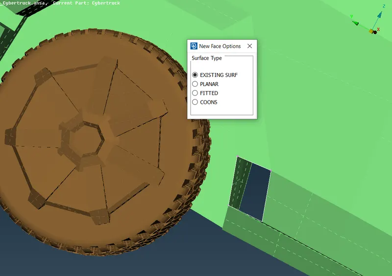
Patching First open surface
Patching second open surface
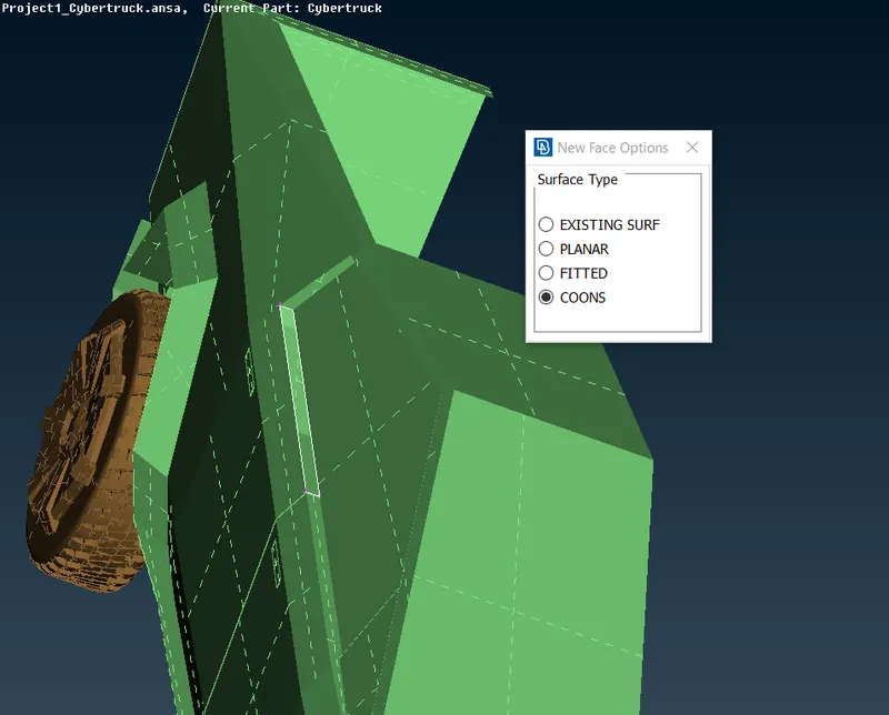
Patching third open surface
In below image image you can see brown color cylindrical surface penetrating with body, that brown part is part of wheel PID and delete that part then patch holes appeared on body and wheels seperately.
-Apply same process for all the missing faces.
-Remove unnecessary faces present inside the model as they don’t have effect on results of external flow simulation.
-To check the geometrical errors in the model, use the Checks Manager tool.
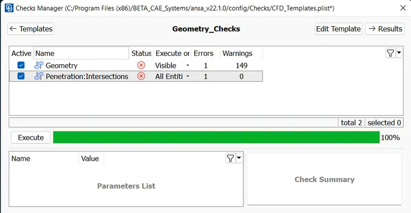
-As observed that there is a Penetration: Intersections error. This error occurs when two surfaces don’t intersect properly.
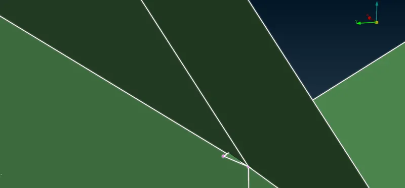
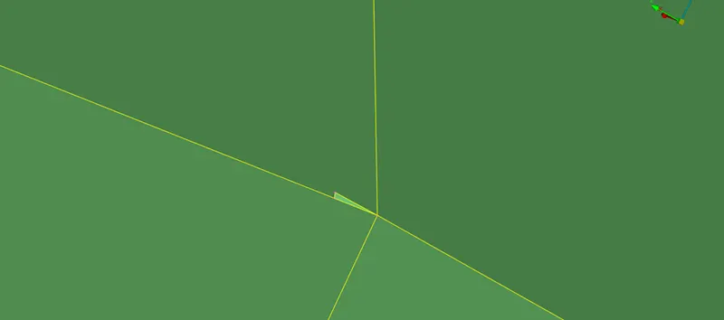
-To rectify this error, use the Intersection tool in the Face module. Select the faces that are need to intersect. Delete the extra faces.
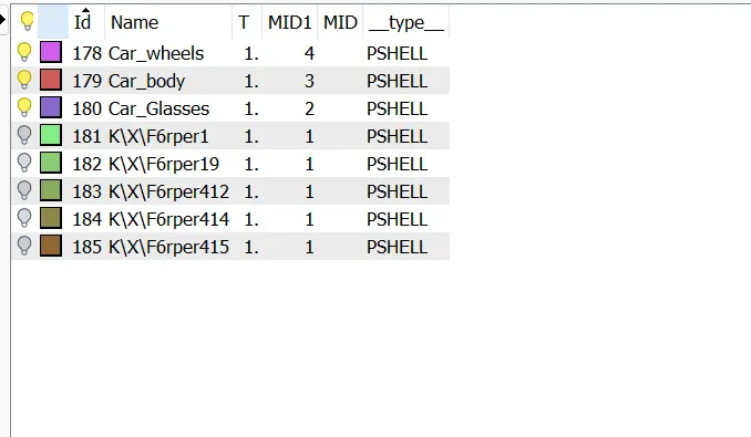
-After rectifying the error, assign the PIDs for the faces. To create new PID, open Properties (CTRL+P) then right click and click on New. Assign the name for the PID. To assign face to PID right click on the PID and click on the Apply and select the face.
PID's Assigned:
Surface Meshing:
-Use the Measure tool to measure the distance between the different Cons. It helps to decide the target length for the surface meshing.
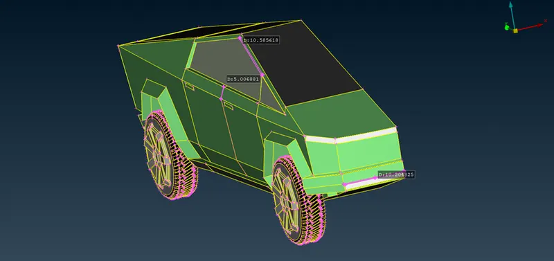
-From the above observation, let us take 3mm as target length with tri elements.
-Click on the Spacing option in the Perimeters module in the Classic Mesh deck. Opt for Auto-CFD option. Click on the Perimeters option and select the model. Middle click to complete the selection.
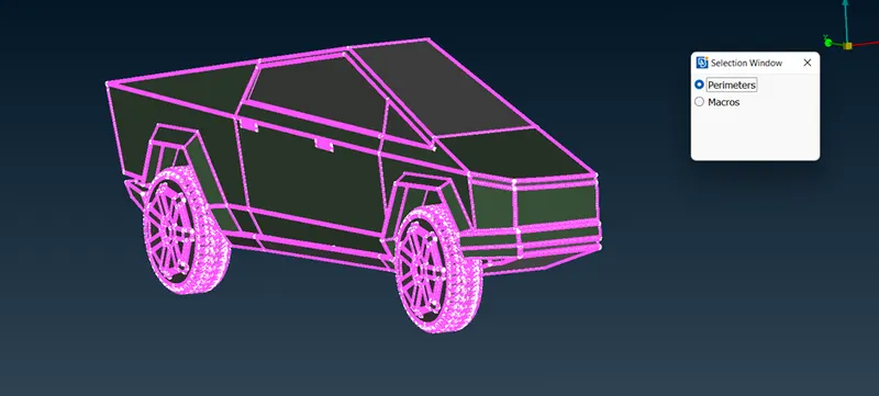
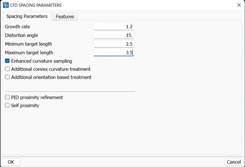
-Specify the Maximum target length as 3.5mm and Minimum target length as 2.5mm. Same for the Macros.
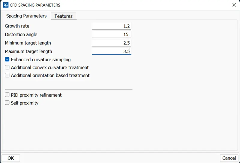
-Set Mesh Parameters as shown in the below image. Click on Apply then on Ok.
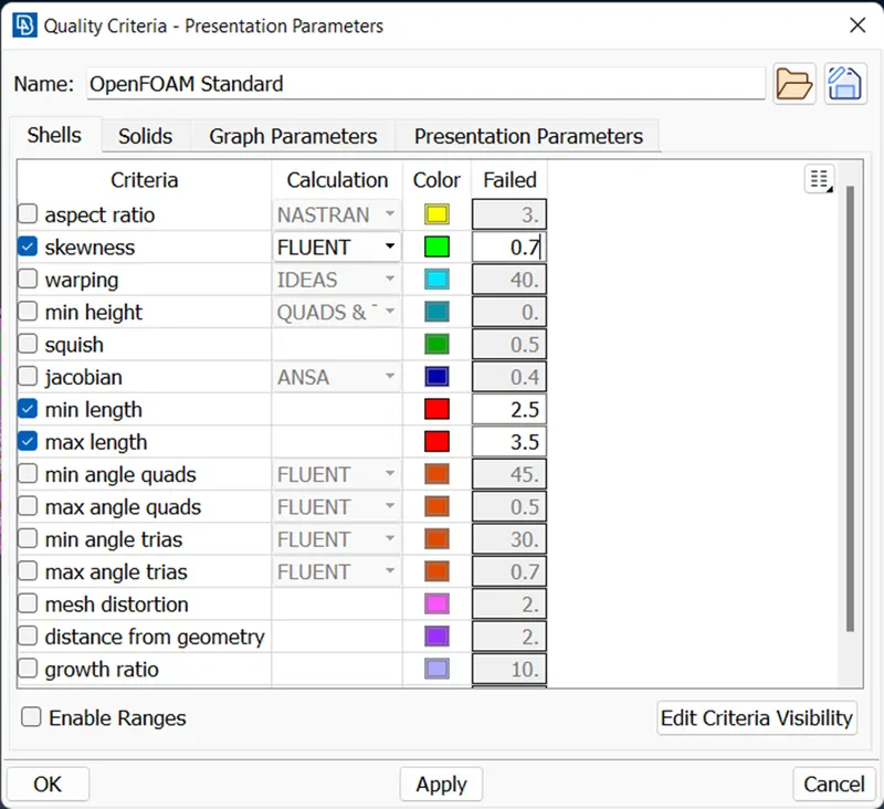
-Set the Quality Criteria as shown in the image below. Click on Apply then on Ok.
-For CFD meshing of the surface of the model, click on the CFD option in the Mesh Generation module. Select all the faces that are to have meshed.
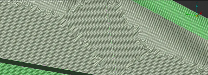
-Make sure to have almost zero off elements (falls under quality criteria). Use the Reconstruction tool in the Shell Mesh module.
-Complete the model by creating another half of the model using the Transform tool. Click on the Copy option of the Transform tool and select the entities. Opt for symmetry with a 3-point Mirror Plane. Select the points and click on the finish to complete the process.
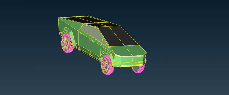
Fig:Full car body after performing symmetry operation
Creating wind tunnel:
a. First, we need to create reference points to create wind tunnel surfaces.
b. Select relative under points in topo mode, create a point below the car taking one reference point and entering the correct values.
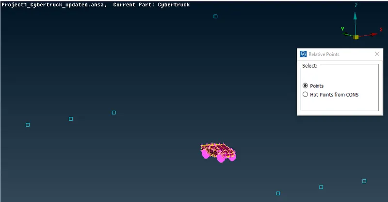
Fig: Creating realtive points to create tunnel surface
c. And calculating the wind tunnel dimensions appropriately, we can create the wind tunnel accurately.
d. The wind tunnel dimmensions are: ( standard distance of the tunnel wrt to car model)
car model: 5906mm .................. (x)
Front surface distance(from reference point): 23624mm .................. (4x)
Back surface distance(from reference point): 35436mm .................. (6x)
Top surface distance(from reference point): 19749mm .................. (3x)
e. After creating the bottom surface use the curves for having the reference of cons, we can delete all the hot points and curves.
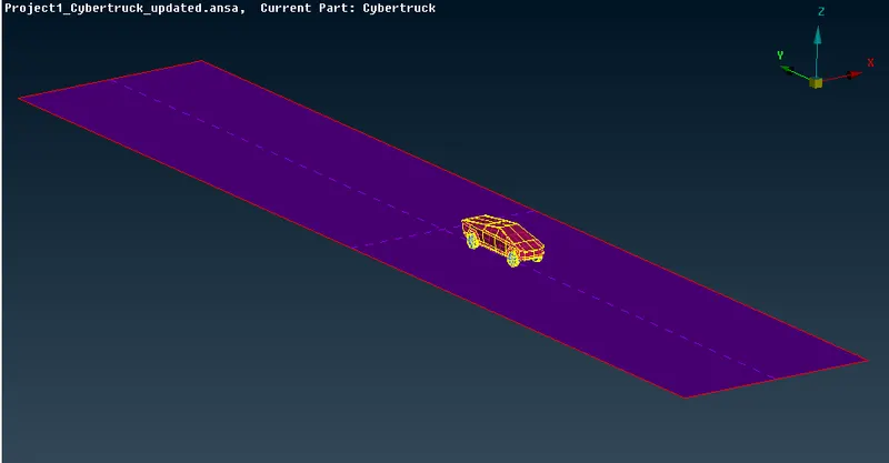
Fig:Tunnel buttom surface.
f. Create all the other wind tunnel surface using the new surface option.
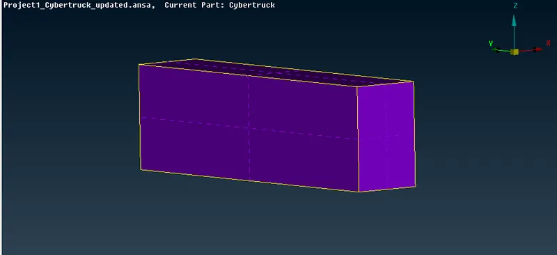
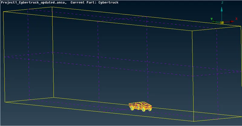
Fig a,b: Wind tunnel
Surafce meshing of wind tunnel:
a. We need to apply surface meshing depending the mesh length near the car and regions far away from it.
b. Therefore we need to apply different mesh lengths at the bottom and top wind tunnel surfaces.
c. We need to use spacing option to have a mesh length varying from the small mesh length size to larger mesh length.
d. Surface meshing can be achieved by doing this accordingly.
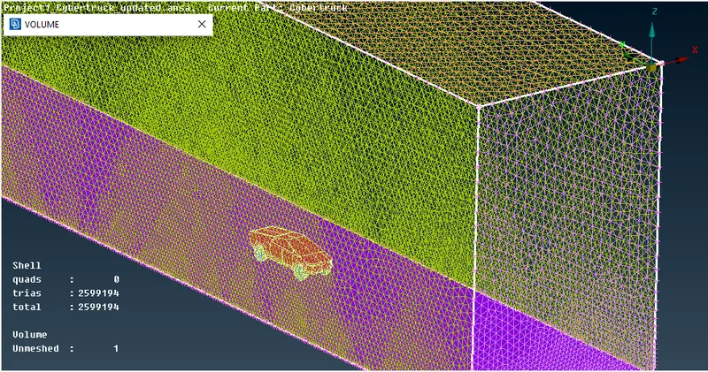
Fig: Wind tunnel surface mesh with varying mesh length
Volumetric mesh of wind tunnel-car volume:
a. Since we are interested only the volume between the car model and wind tunnel, we can delete other volumes of the car model which is not necessary.
b. Since performing the volumetric mesh takes 2-3 days, volumetric mesh is not performed as given by the challenge question.
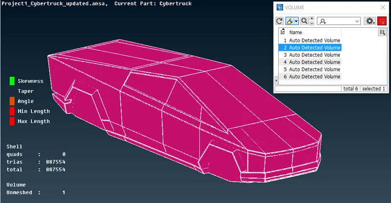
Fig: Car body volume
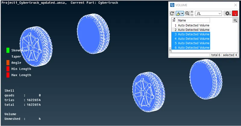
Fig: Tyres volume
Learning outcomes:
a. Learnt the complete CFD meshing skill from skratch.
b. Performed various topo clean-ups using different tools.
c. Understood the need of double cons and removing unecessary triple and single cons.
d. The use of symmetry helps in reducing the work time and helps in having accurate results with less work.
e. Create surfaces using the reference hot points by using relative points.
f. Surface meshing for different components and their varying mesh lengths.
g. Using spacing option in surface meshing helps in having varying mesh lengths along the surfaces.
h. Using re-construct option to reduce off elements to a level where we can edited it manually.
i. Using the mesh modifying tools like move, split and smooth options.
CONCLUSION:
- Working on tesla model gave ideas about different meshing tools available in ANSA.
- Learned surface meshing and Geometry cleanup in much detailed manner. Challenges faced helped to understand tools better
- Learned how to use curve tool, how to create win tunnel with help of points and curves
- Learned about dimensions of wind tunnel, like what dimesnions to give based on model size
- Learned how to de meshing when there are different PIDs with different mesh length in contact with each other
- lerned use of reconstruct and move tool
- worked on how to fix off elements
- Advance topo-cleanup