Project 1 : CFD Meshing for Tesla Cyber Truck
Objective:
Firstly, completing topology cleanup, afterwards generating surface mesh. Eventually, creating wind tunnel geometry surface meshing and extracting single volume model for further volumetric mesh generation.
Geometry
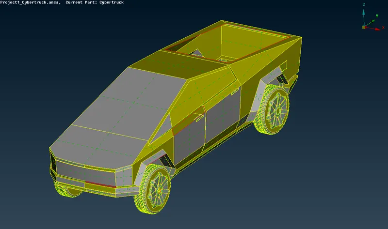
Figure 1
Topology optimization
Within the 3d model we encounter multiple singlecons (opened surfaces) which we must resolve in order to get perfect geometry for meshing.
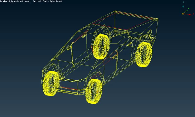
Figure 2
In the figure 2 contours in yelow detect doublecons which are closed surfaces and therefore this type of cons are not a problem, however contours in red identify singlecons which should be eliminated.
Before, starting resolving singlecon issues, half of the 3d model will be temporarily deleted, because the model is symmetrical.
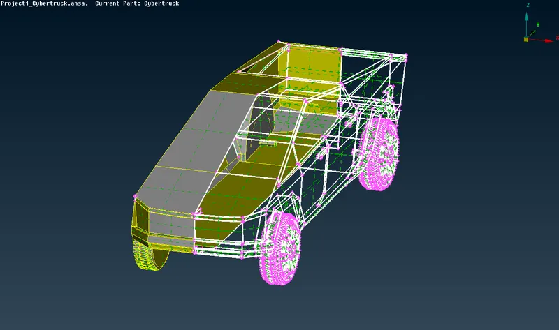
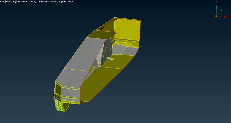
Figure 3
As shown in the Figure 2 were detected several singlecons, which were pretty straightforward to resolve. We just created new surfaces within the open areas using the command tool "New" in the "Faces".
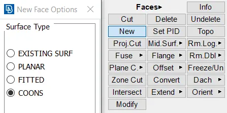
Figure 4
Despite fo the quick resolve of the singlecon issues, we have a big open area at the rearside of the car, which should be constructed as a so called "Truck Bed". We use "Curves" to create reference curves as shown in the Figure 5 (Curves are marked in white color). Surfaces of the constructed "Truck Bed" is shown in the Figure 6.
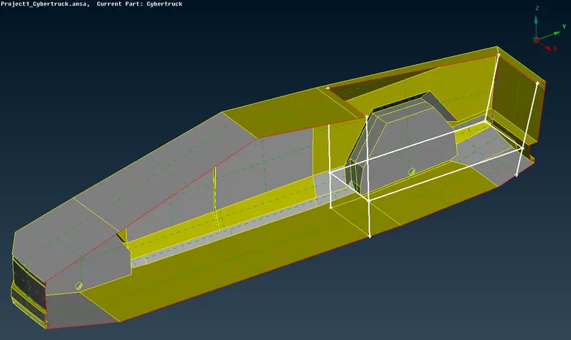
Figure 5
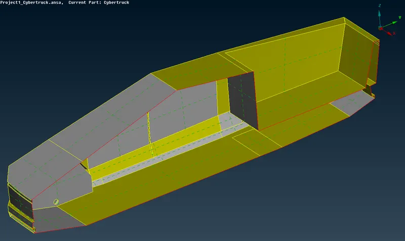
Figure 6
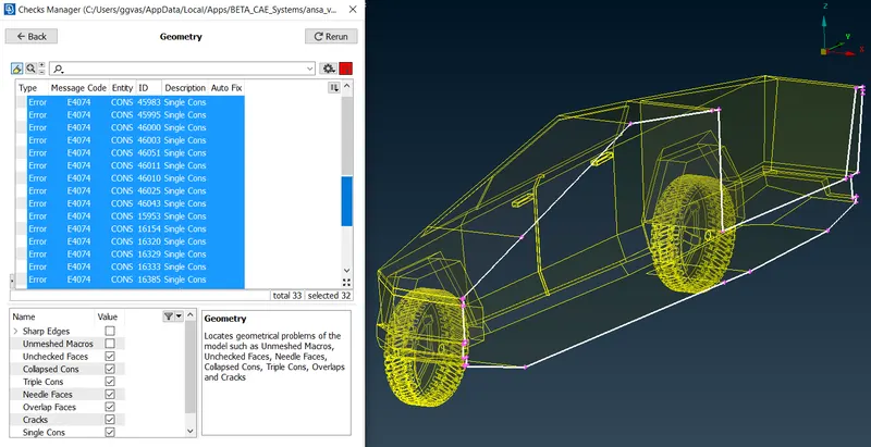
Figure 7
According to the Figure 7, It's clear that we do not have a any topology issues except the singlecon at the edge of the half-cut of the 3d Model (Shwon in white color), which will be resolve after we recreate the second half of the Cybertruck.
Property ID (PID)
Now it's time to apply property ID's for specific regions within the complete 3d Model.
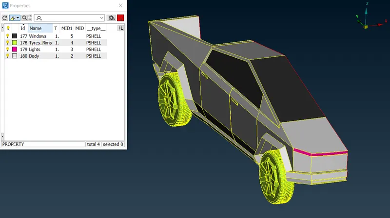
Figure 8
In the Figure 8 you see that the whole geometry has been divided into different regions, named accordingly and created Property IDs (PIDs).
Surface Meshing
Target lengths for the different parts of a model are as follows:
- Body - 10 mm
- Lights - 4 mm
- Windows - 6mm
- Tyres_Rims - 3 mm
for "Lights" we have quality criteria and Mesh parameters shown in the Figure 9.
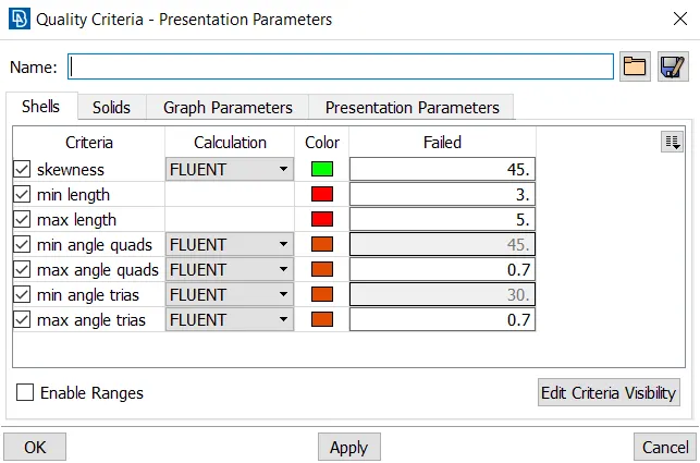
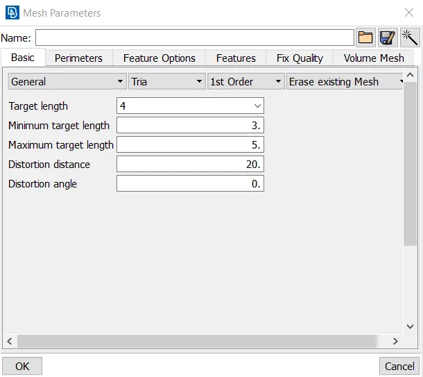
Figure 9
for "Windows" we have quality criteria and Mesh parameters shown in the Figure 10.
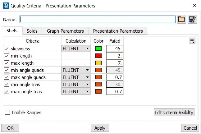
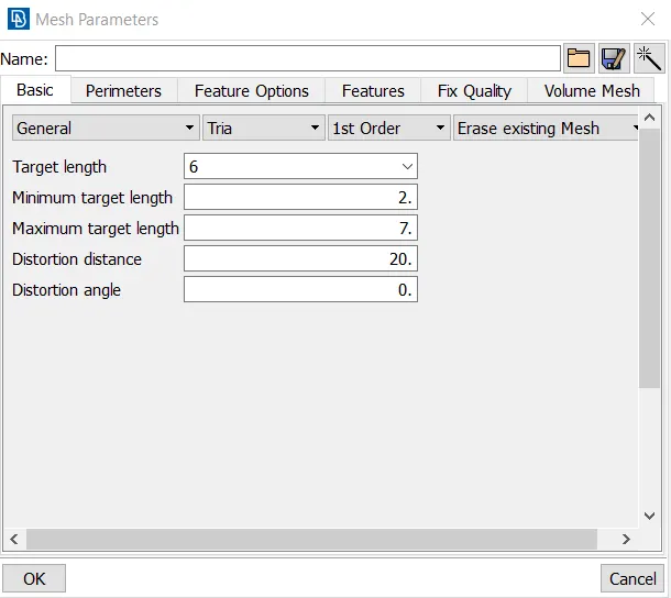
Figure 10
For "Tyres_Rims" we have quality criteria and Mesh parameters shown in the Figure 11.
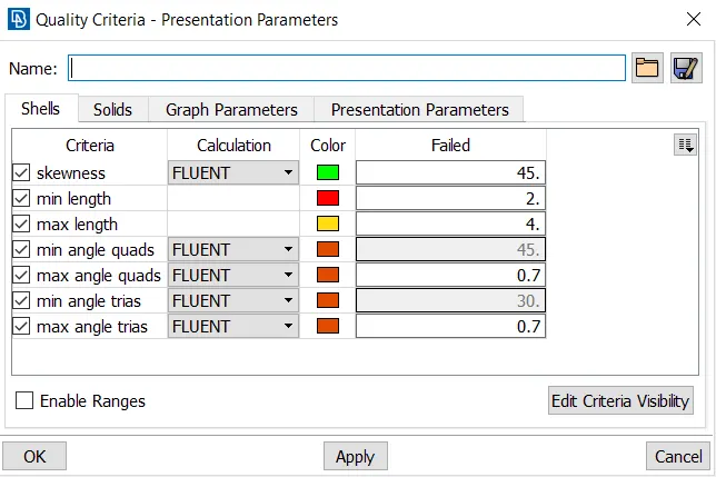
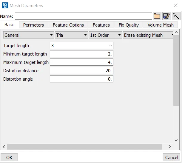
Figure 11
For "Body" we have quality criteria and Mesh parameters shown in the Figure 12.
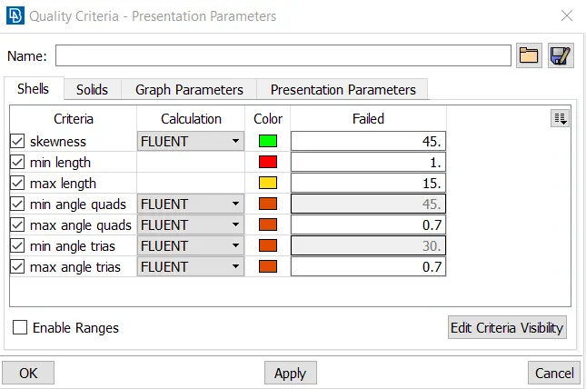
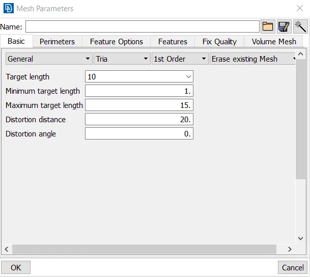
Figure 12
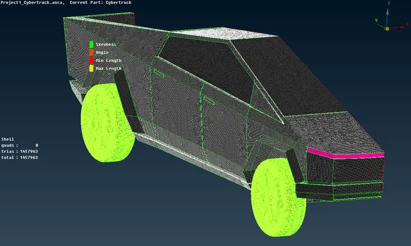
Figure 13
Creating the second half of the Cybertruck
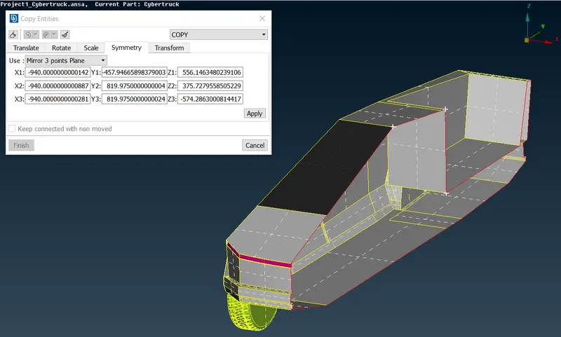
Figure 14
In the Figure 14 It's shown that to create the symmetry we should select 3 any points which are located on the edge of the symmetry plane. after selecting those points and executing the command we get the complete geometry (Shown in the Figure 15).
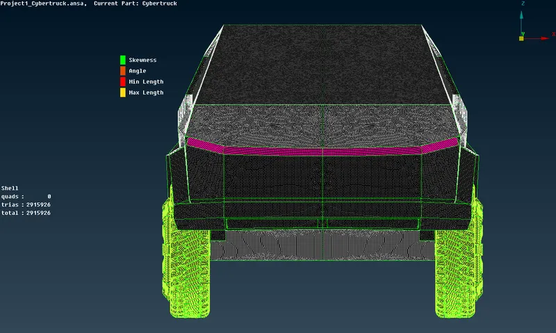
Figure 15
Wind Tunnel
Before creating the wind tunnel surfaces we should know the distances at which the surfaces will be created. Firstly, we should find out the length of the car itself.
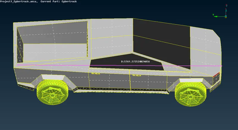
Figure 16
According to the Figure 16 the car length, in other words, aerodynamical characteristic length is approximately 5761mm. Now we create front surface nodes. wind tunnel front surface must be located at the distance of the 4 times the length of the car from the front edge of the car itself. therefore the distance should be approximately `4*x = 23000mm` (Shown in the Figure 17)`
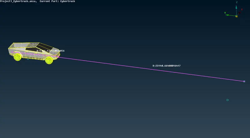
Figure 17
wind tunnel rear surface is located at the `6*x` distance which will be `6*5761 = 34566mm` (Shown in the Figure 18).
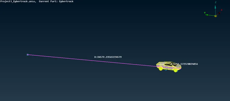
Figure 18
In order to determite the height of the wind tunnel we should locate the top surface at the `3*x` distance from the top surface (roof) of the car, which is `3*5761 = 17283mm.` (Shown in the Figure 19)
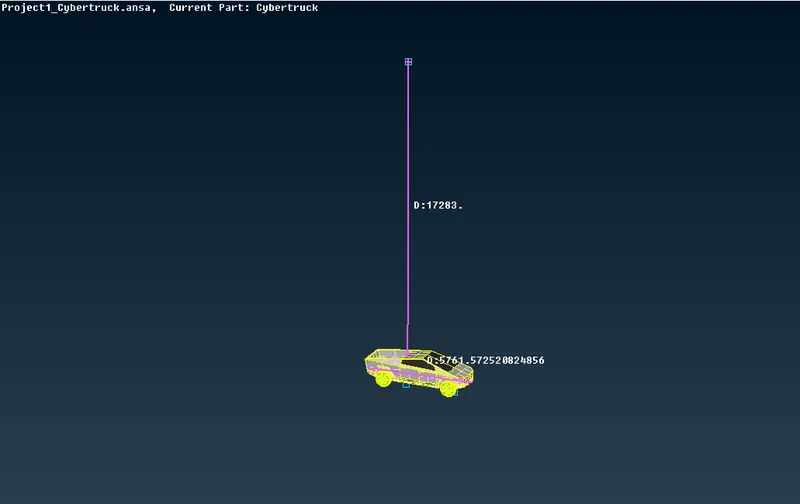
Figure 19
Wind tunnel width should be `2*x`, therefore `2*5761 = 11522mm` (Shown in the Figure 20)
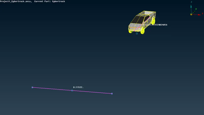
Figure 20
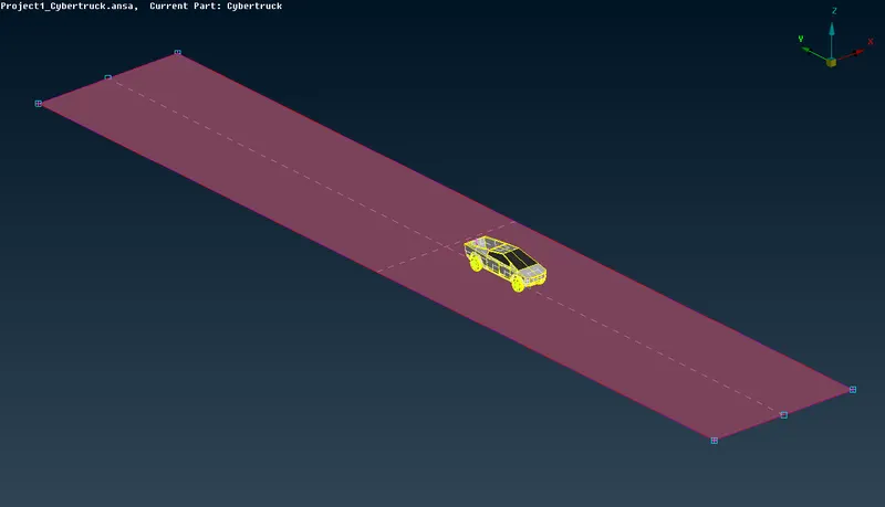
Figure 21
In the Figure 21 Base surface of the Wind tunnel is shown.
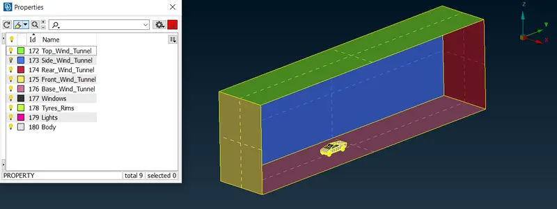
Figure 22
- Surface Mesh of the Wind Tunnel
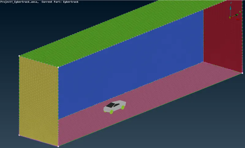
Figure 23
Volumetric Mesh
In order to identify Volumes we sue command "define - Autodetect" which detected 2 volumes.
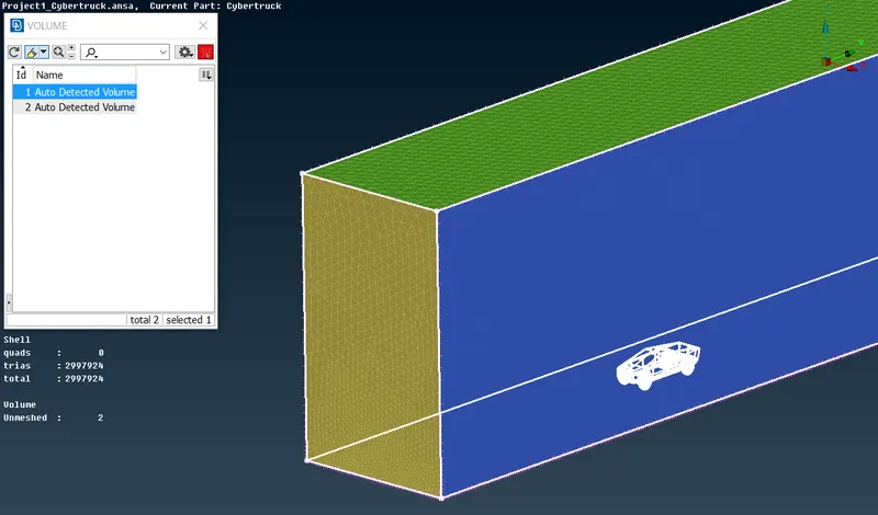
Figure 24
In the Figure 24 the first detected volume is the volume we need for the CFD simulation, This is the volume between the car and the wind tunnel surface, the other volume are solid volum (car volume) which should be deleted.
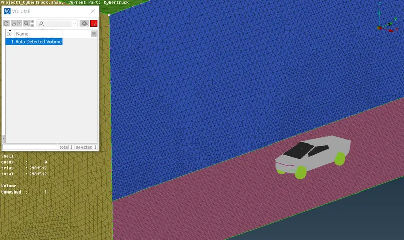
Figure 25
In the Figure 25 the volume between the car and the wind tunnel surface is shown. Now we can perform Volumetric meshing using the command "Remeshing", however the number of surface mesh elements is too high and as we know the size of the tunnel is pretty close to the real one, therefore meshing would take a lot of time.
Conclusion
We successfully performed topology cleanup of the entire model, created surface mesh, Furthermore created Wind tunnel around the car and advanced the geometry to the one volume model which could be used for further reaserch (CFD).