Project 1 : CFD Meshing for Tesla Cyber Truck
CFD Meshing For Tesla Cyber Truck
Aim :- To check all the geometrical errors and to perform the meshing for given Tesla cyber Truck model. Also we have to create a wind tunnel around the truck for volumetric mesh.
Target lengths taken for different PIDs
Truck body - 6mm
Truck Front wind screen - 7mm
Windows - 5mm
Wheels - 3mm
Base of Tunnel - 100mm
Top of Tunnel - 500mm
Front of Tunnel - 100 to 500mm (variable mesh)
Back of tunnel - 100 to 500mm (variable mesh)
Side of Tunnel - 100 to 500mm (variable mesh)
Theory :- ANSA is a CAE pre-processor tool used for Finite element analysis and CFD analysis widely used in the automotive industry. ANSA stands for Automatic Net generation for Structural Analysis. ANSA maintains the association between CAD geometry and FE mesh. It carries several proprietary algorithms for meshing suitable for both CFD and structural models.
Surface mesh - Surface mesh is a representation of a surface that consists of vertices,edges and faces. It is a set of polygonal faces, often triangles, that, taken together from a surface covering of the object. The advantage of a surface mesh is that it is fast to generate and works very well for visualization.
Volumetric mesh - Volumetric meshes are polygonal representation of an interior volume of an object.
Procedure :-
Download and open the ".ansa" format file of given Cyber Truck model in ANSA software. It will be in the wireframe mode.
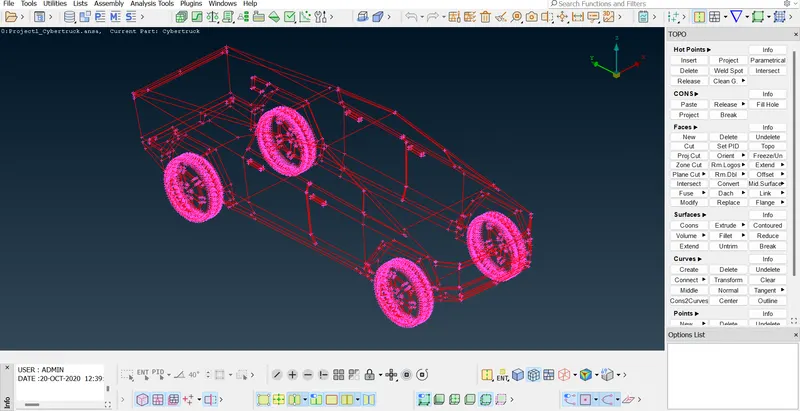
Trun on to shadow mode and turn on PID.
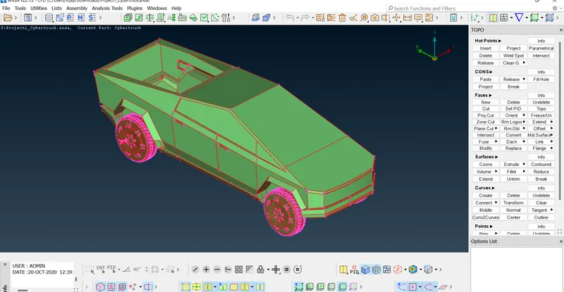
Use 'Topo' function and apply for the entire model
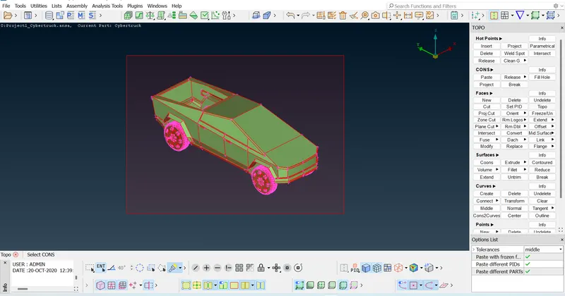
Now we can observe the formation of double CONS.
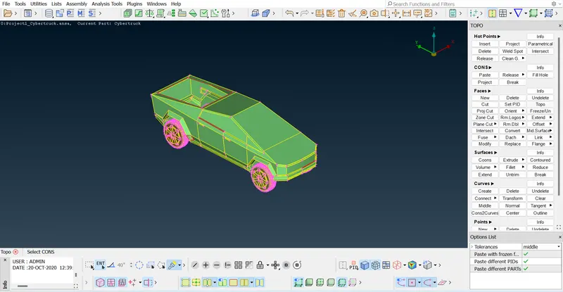
Now close the opened surfaces and try to reduce the single CONS using the better 'NEW' face method
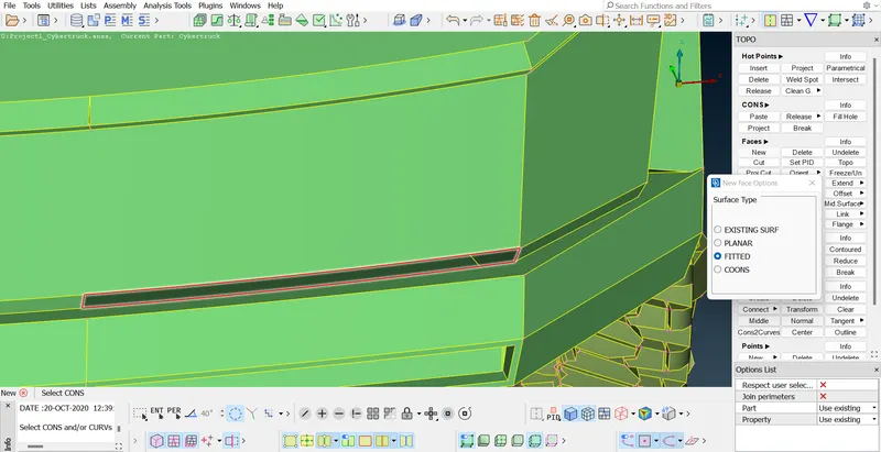
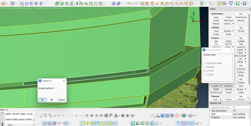
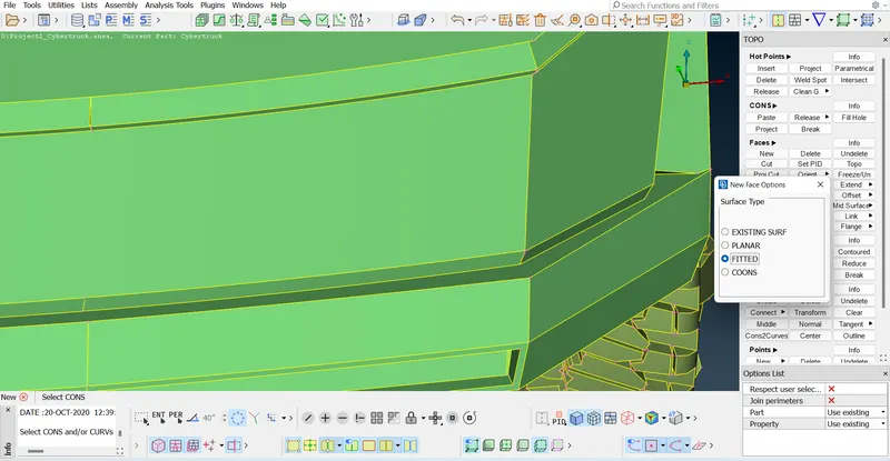
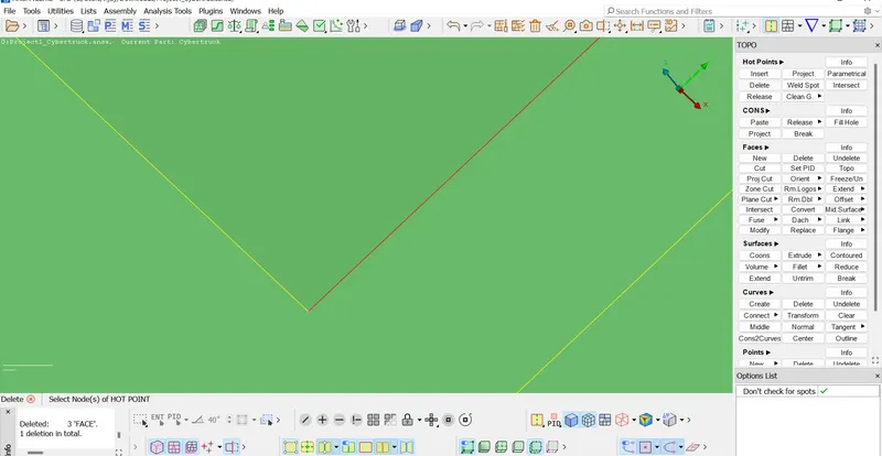
Deleting the unwanted entities
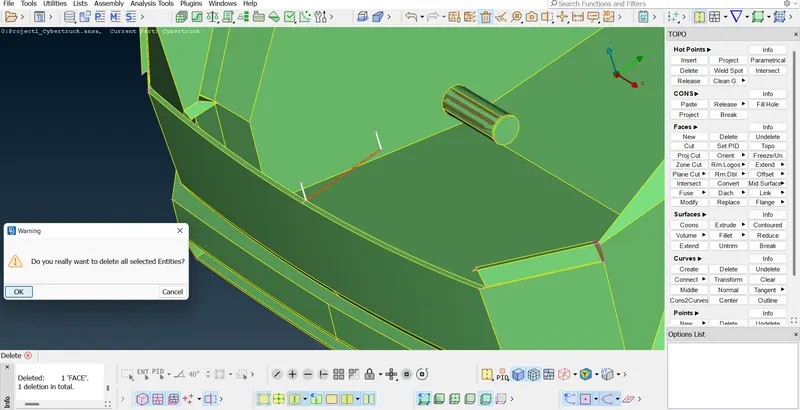
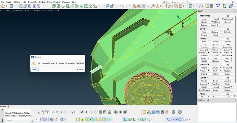
Closing the top opened surface
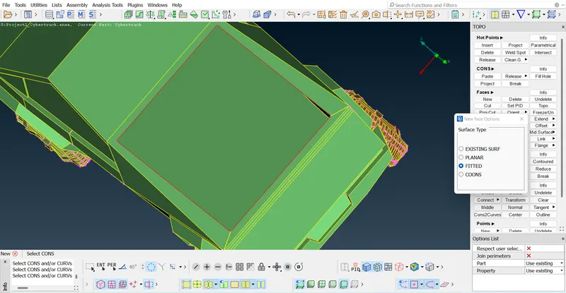
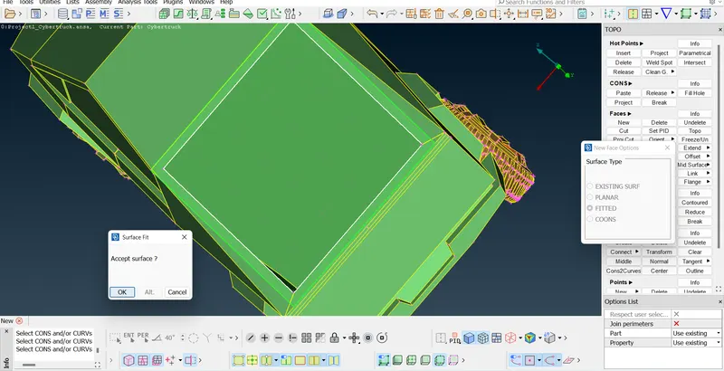
Deleting the unwanted hotpoints
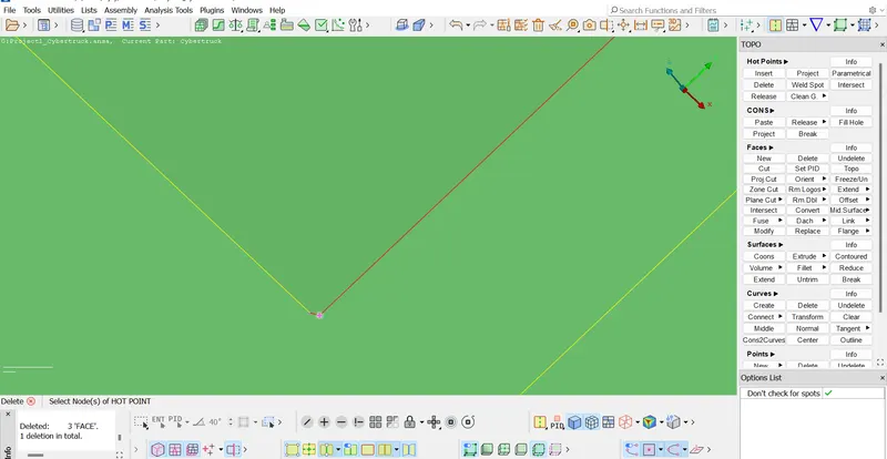
Solving the penetration errors using Intersect option
Select the penetrating face as First face
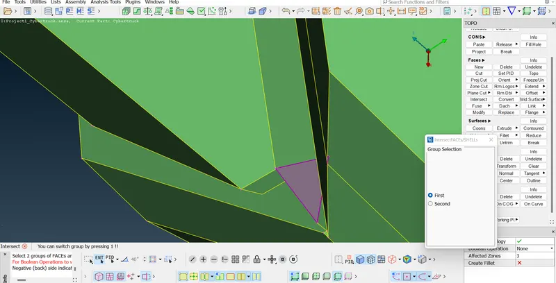
And then select the other face/faces where the first face is penetrating into.
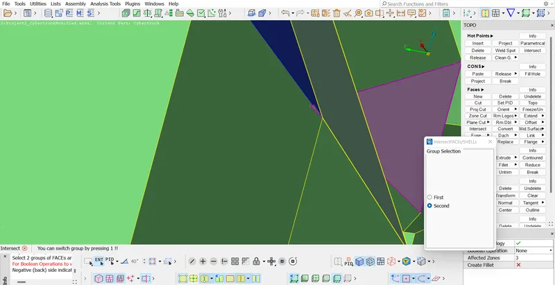
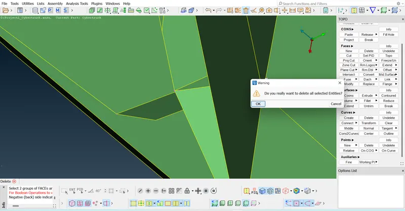
Now the CONS will be formed and delete the unwanted faces.
Penetration error checking
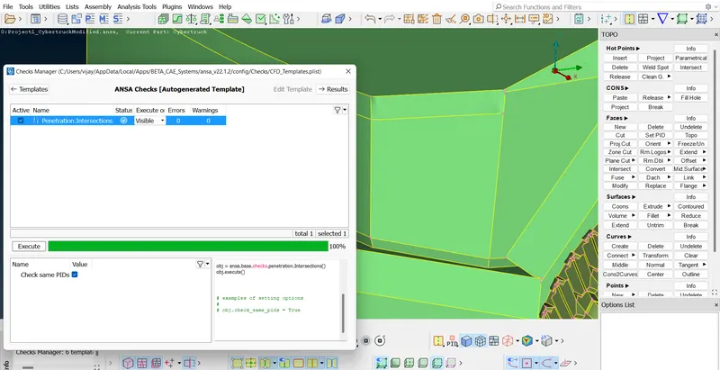
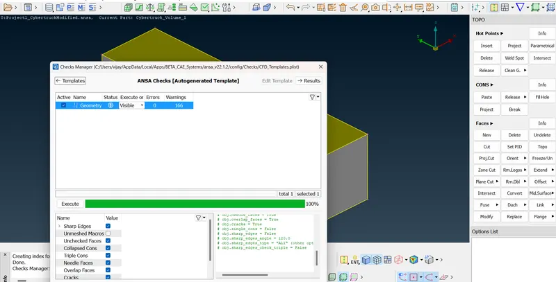
We can see that there are no geometrical errors. To reduce the convex CONS, convex CONS and mixed CONS warnings, try deleting the surfaces and create new surfaces
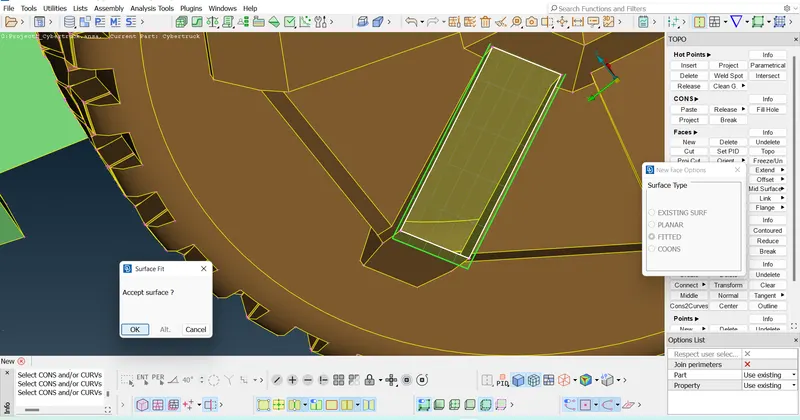
Filling the missed surfaces in Wheels part
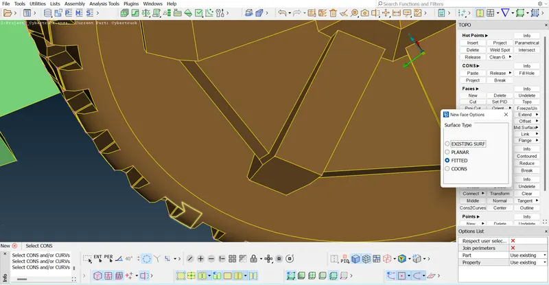
Deleting the unwanted entities which are penetrating into other parts
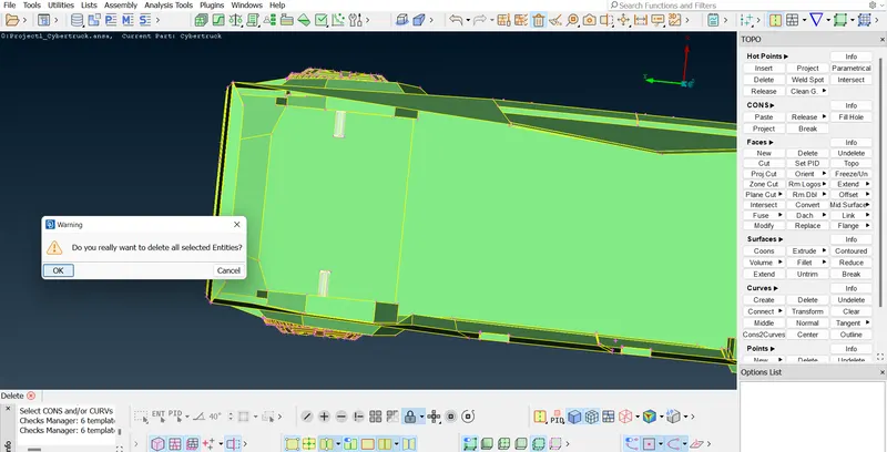
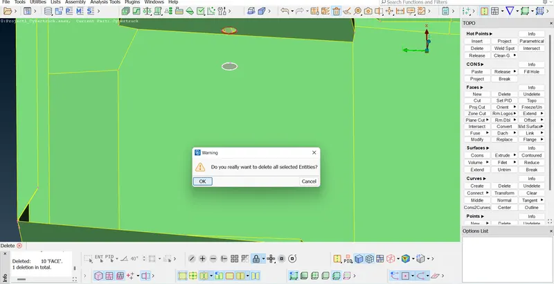
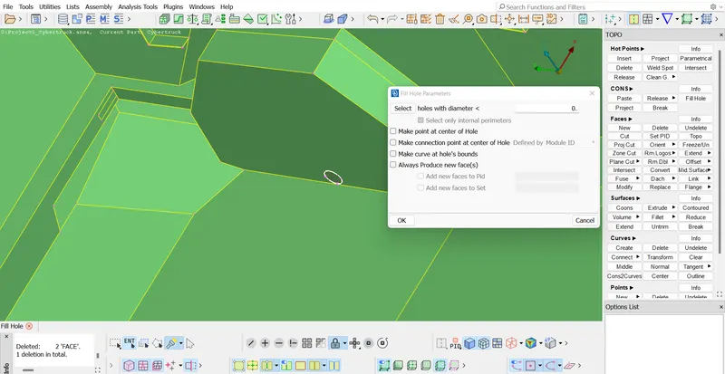
Use Fillhole function and close the surfaces.
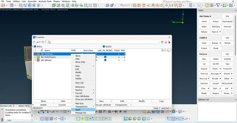
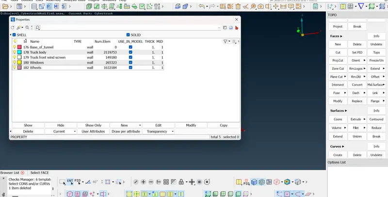
Assigning the PIDs - Create a new shell property and then give a name to it and then right click on it and apply to the geometry parts.
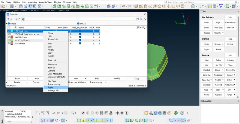
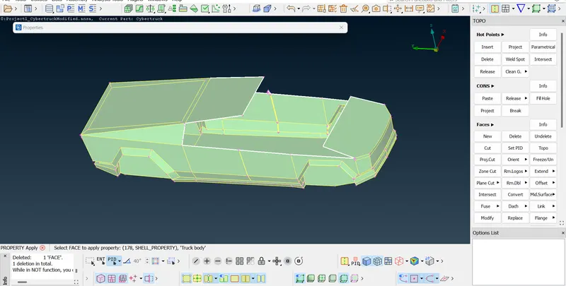
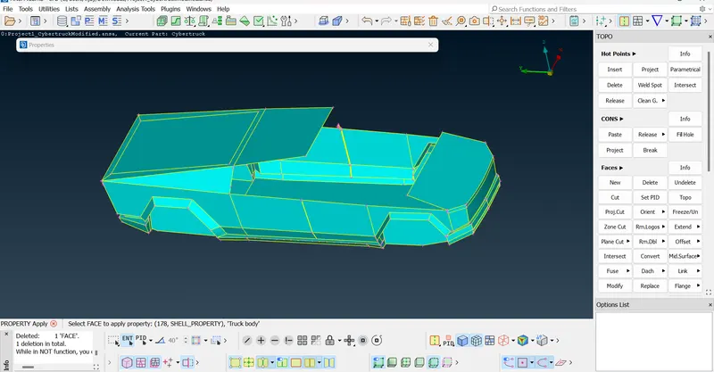
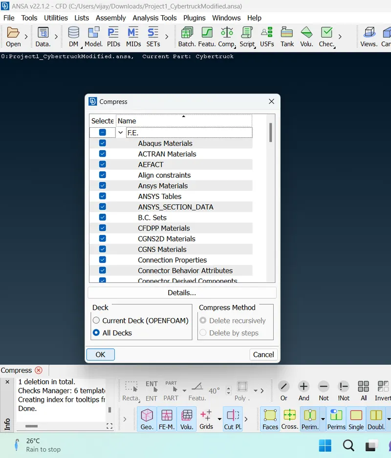
Use Compress option to delete the dummy PIDs
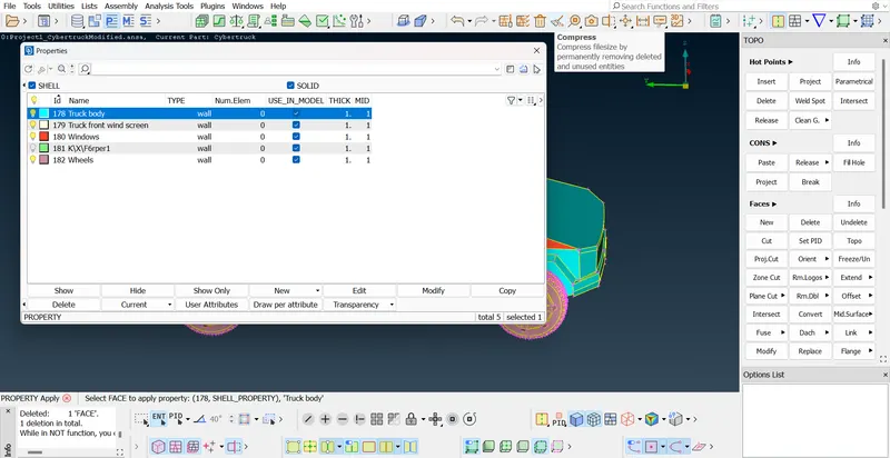
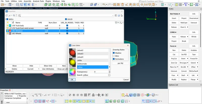
Assign different colours for different PIDs
Meshing
Start meshing individual PIDs
1) Windows - Target length - 5mm
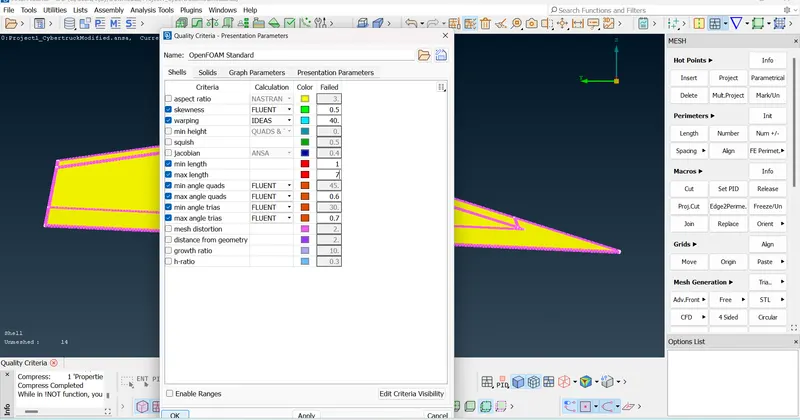
Go to quality criteria and give min length = 1 and max length = 7
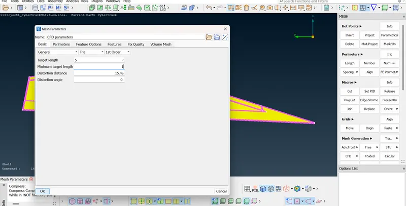
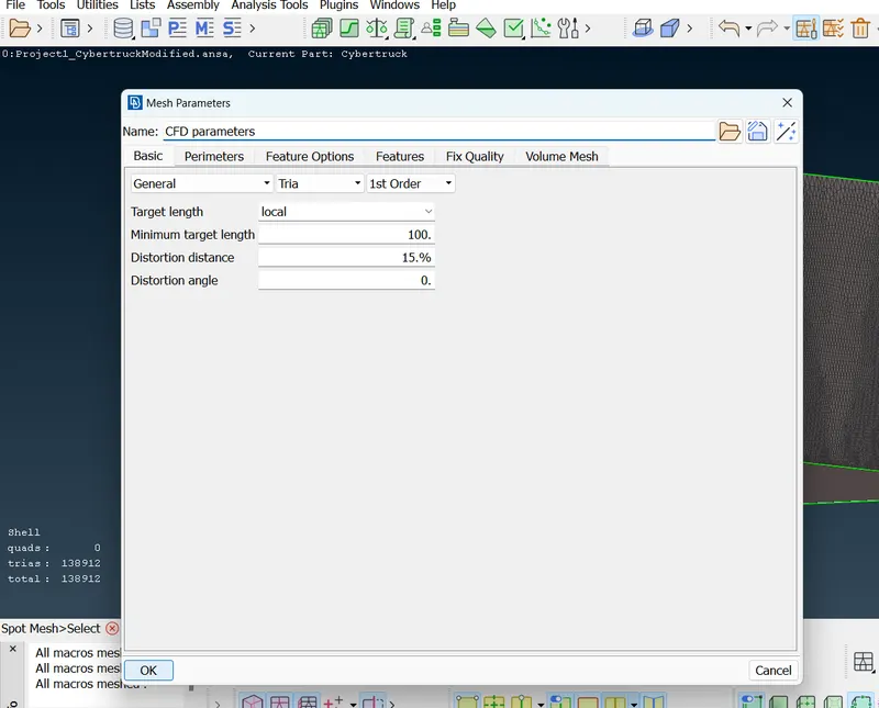
Similarly go to Mesh parameters and give Target length = 5mm and minimum target length = 1mm
Go to Perimeters > Length and then Box-select the windows and give length as 5mm
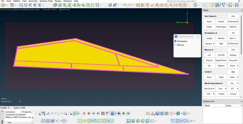
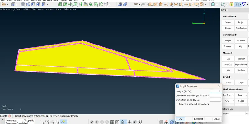
Similar procedure for Macros and then do long press on Spot mesh under Mesh generation processes and then select 'Visible'
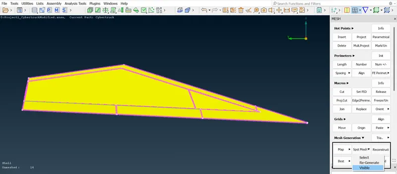
Wait for few seconds for ANSA to complete the surface mesh.
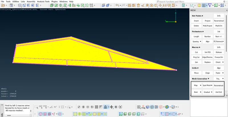
Click on hidden elements option which is next to wirefrme option and we see the off elements. Right click on off elements and click on improve
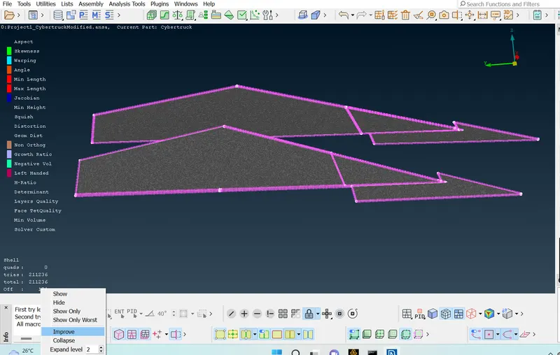
Reshape - Go to next page
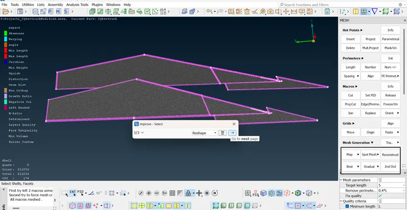
ANSA will select the edges - then again go to next
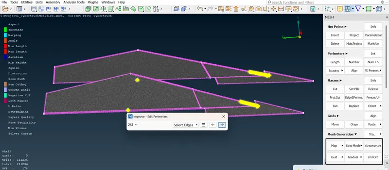
Now we can see that there are no off elements.
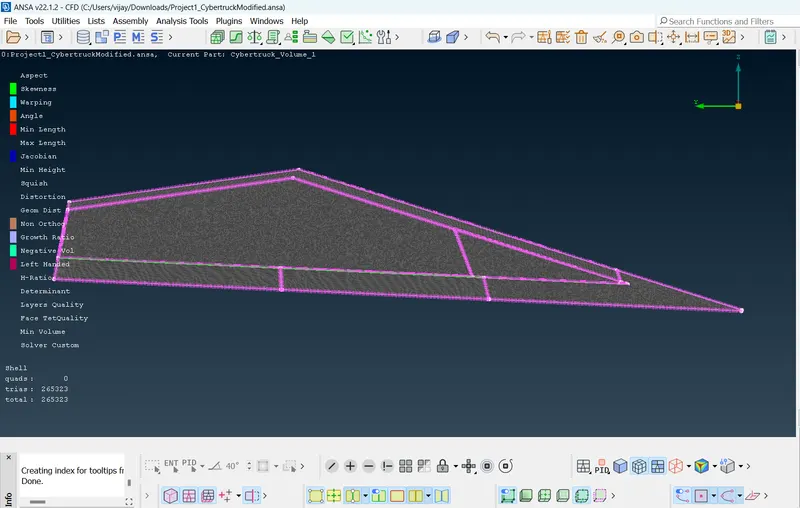
2) Truck Front Wind screen - Target length - 7mm
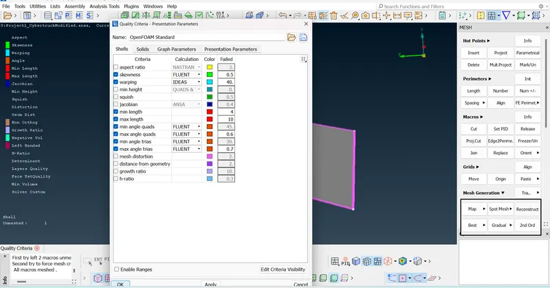
Go to quality criteria and give minimum length = 4mm and maximum length = 10mm
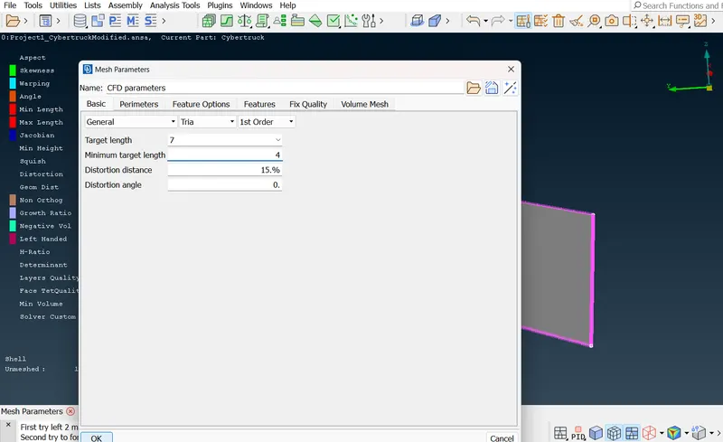
Go to Mesh parameters and set target length = 7mm and give minimum length = 4mm
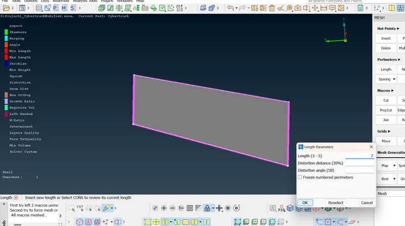
Now set Perimeters > Length for the PID and proceed with meshing.
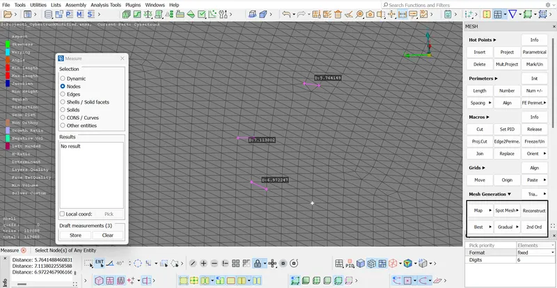
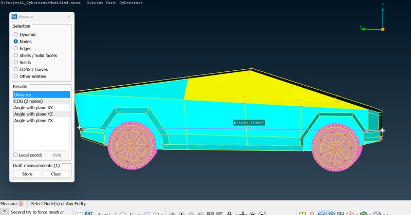
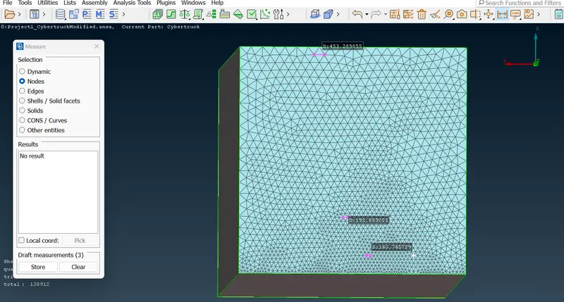
Using 'Measure' tool we can find the distance between the nodes of meshing elements.
Truck body - Target length - 6mm
Go to quality criteria and change minimum length to 3mm and maximum length to 10mm.
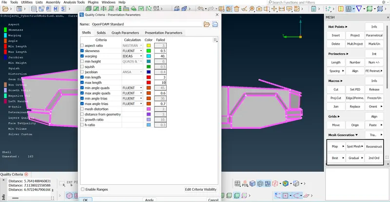
And then go to mesh parameters and set the target length for 6mm and min length for 3mm and set the length for perimeters and macros.
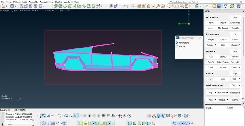
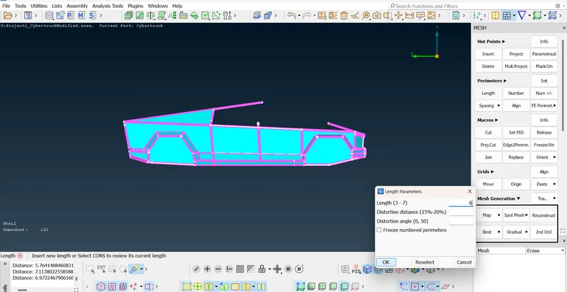
After meshing the Truck body,try to reduce the off elements.
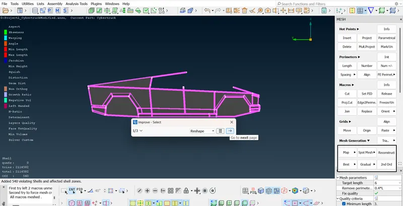
Similarly do mesh for the Wheels PID with a target length of 4mm.
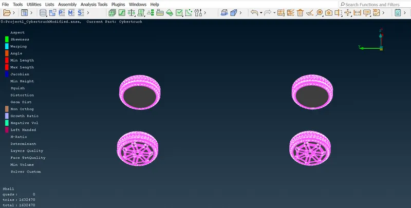
Results :-
Surface Meshing for the entire Truck model was done with 0 off elements.
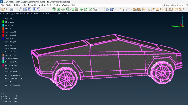
Now we have to create a Wind Tunnel around the cyber Truck.
Go to TOPO. Measure the length of the Truck and it is 5849mm
Select a random node from the base of the truck and give a point relative to it under the truck at a distance of 500mm.
Go to Points > Relative
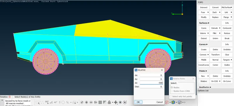
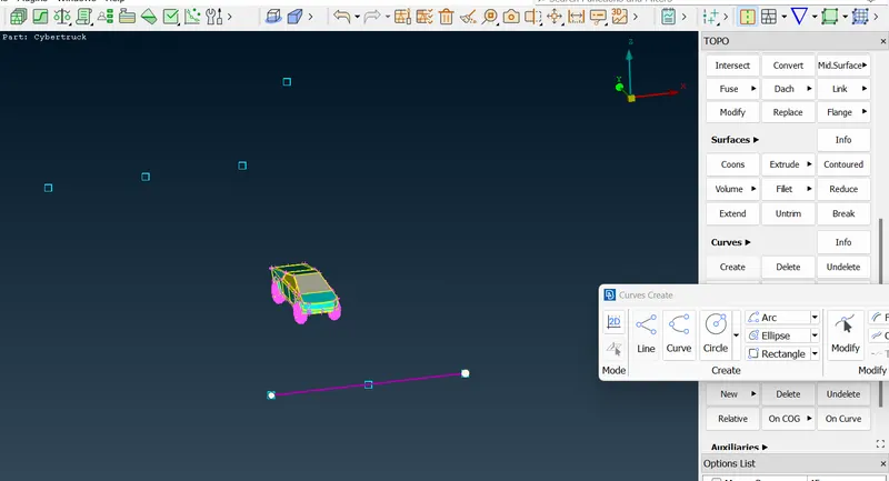
Now we can see a point under the truck and with reference to that point create other points at front side, back side , top of the truck and left and right side of the truck.
Let's create a point at 25000mm at the back side of the truck i.e 4 times its length approximately.For this we have to give dy = 25000
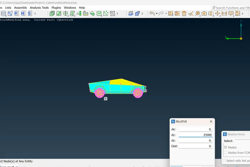
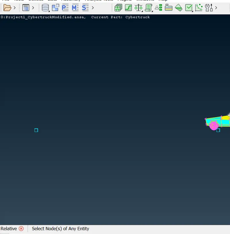
Similarly create a point at front side of the truck at 15000mm relative to the initial point under the truck and at 10000mm top of the truck and at 5000mm both right and left sides of the truck.
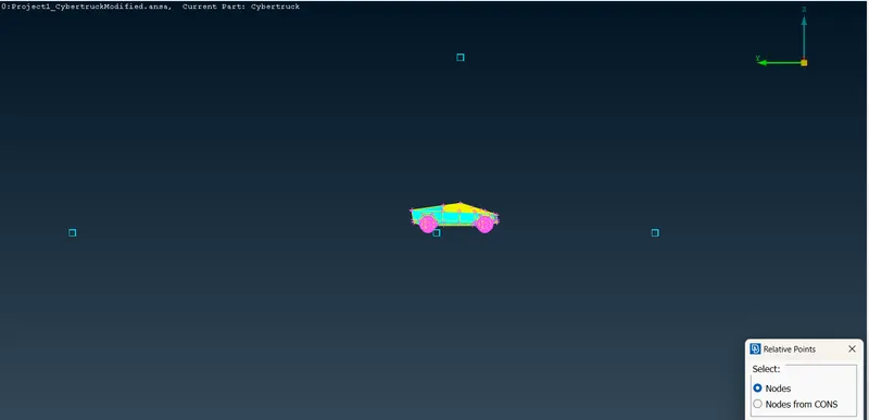
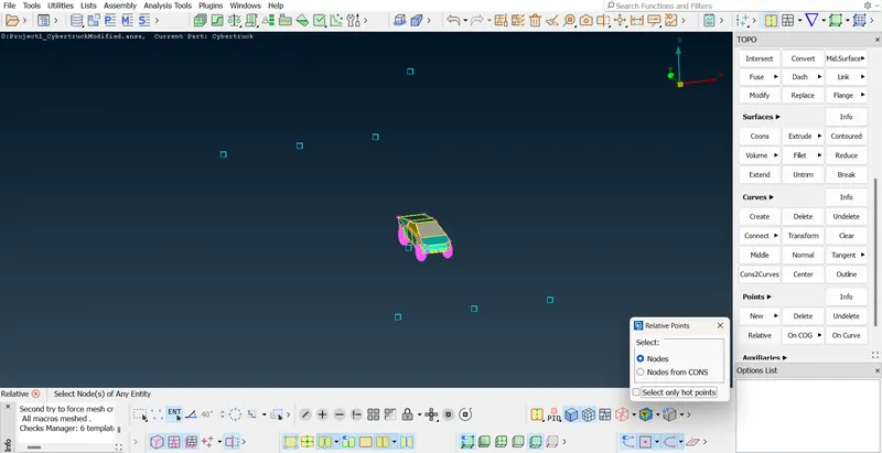
Now to create a base surface of the tunnel we have to use Create function in Curves section to join all those points.
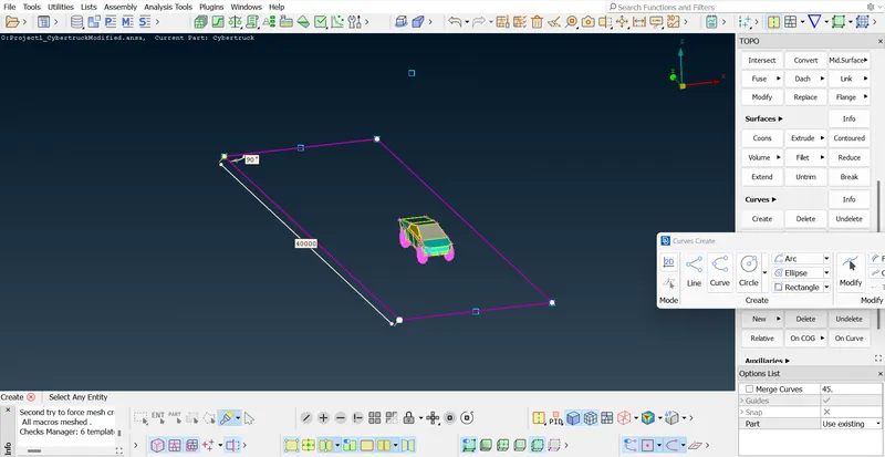
Using New face method create the base surface
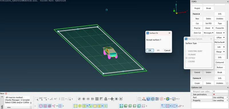
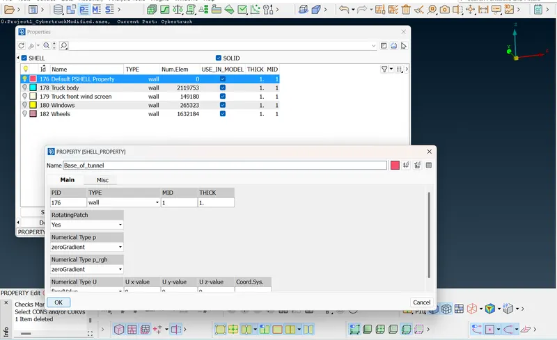
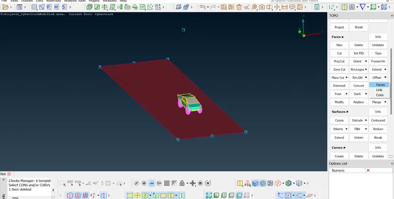
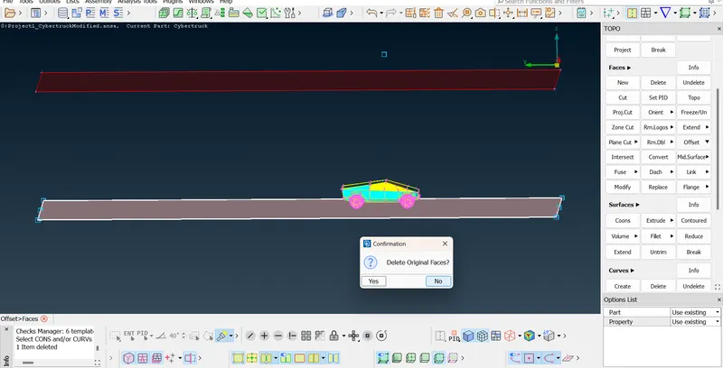
Using 'Offset' function create the top surface of the tunnel.
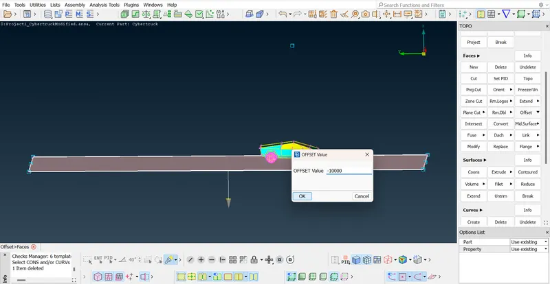
Don't delete the original face(base surface)
Delete all the curves and points which were created earlier.
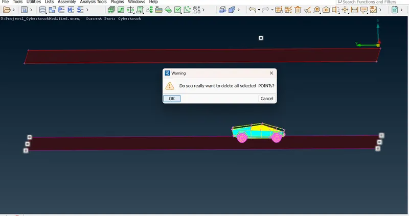
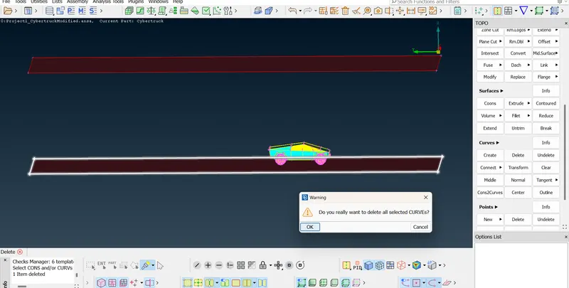
Using CONS method create all the remaining surfaces of the tunnel and assign the PIDs
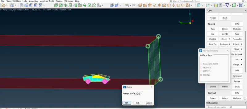
Meshing of the Tunnel part :-
Meshing the Top of Tunnel with 500mm as target length
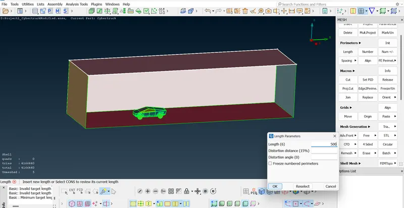
Meshing the Base surface of Tunnel with 100mm as target length
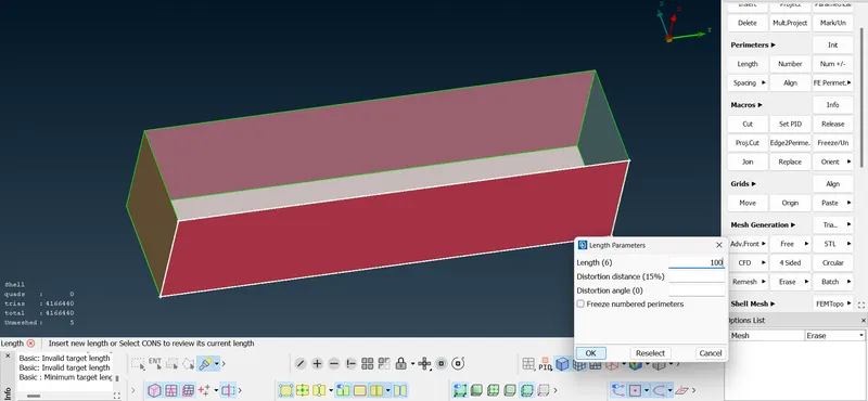
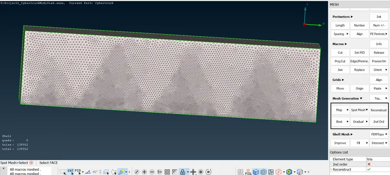
For Side surfaces and for front & back surfaces there must be a variable mesh since the top and base surface mesh lengths varies. So use Spacing option under perimeters and set Biasing to geometric and give Dstart = 100 and Dlimit = 500
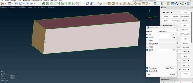
Select all the Side edges
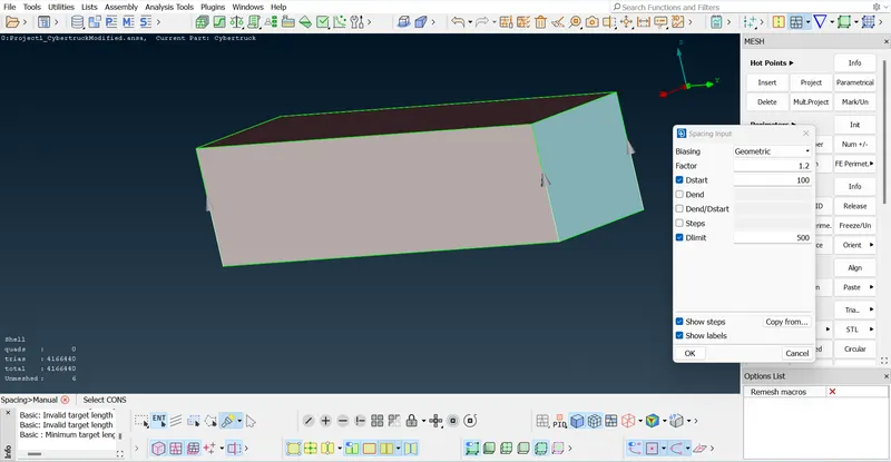
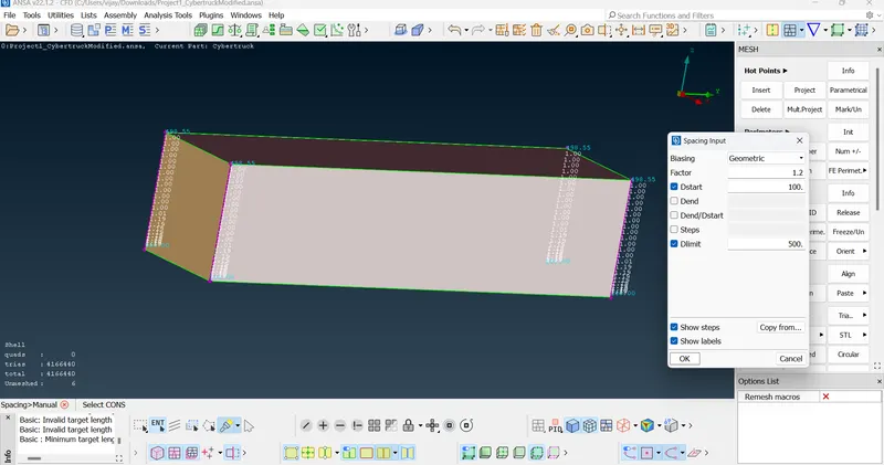
Change the minimum and maximum lengths in the quality criteria and while meshing for side surfaces and front & back faces of Tunnel set the Target length to 'local'
Front face of Tunnel
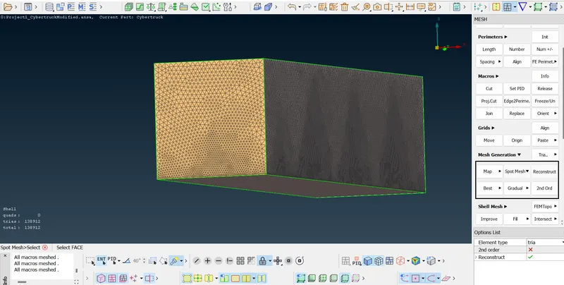
Back surface of Tunnel
Side surfaces of Tunnel
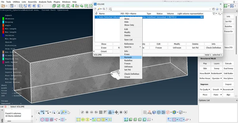
Now Go to Volumetric meshing
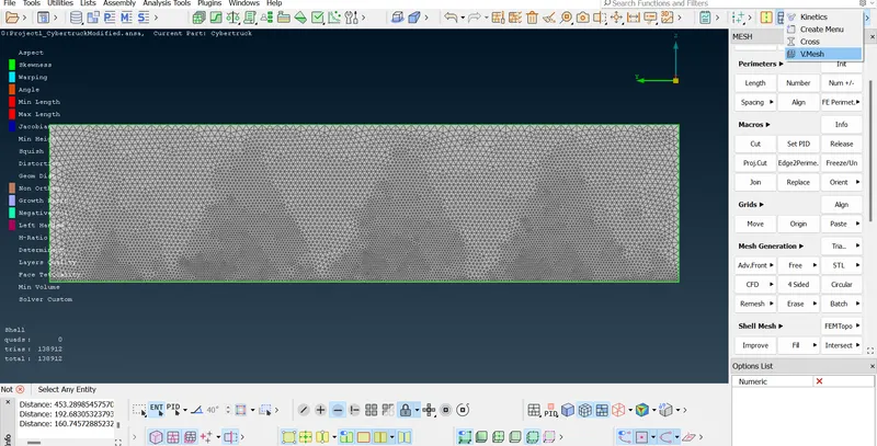
Go to Volumes and click on Define function
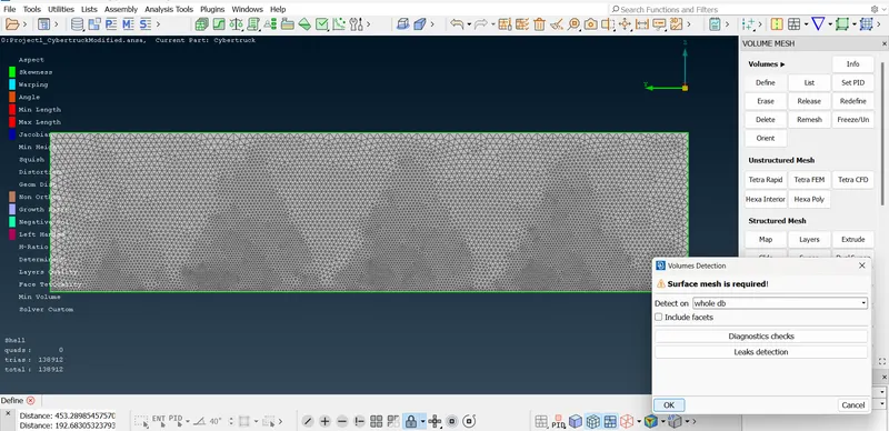
Click on OK, ANSA will detect all the volumes from whole data base and then delete the unwanted volumes(Truck volumes)
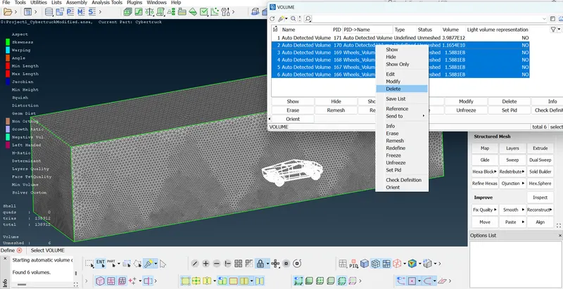
Click on OK
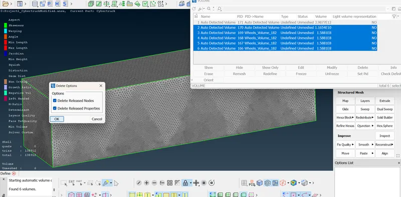
If we do right click and select Remesh, ANSA will start meshing the entire volume with Tetra elements,since the volume is so large it may take 2 days or more for volumetric meshing.
Learning Outcomes from this Project :-
1. Lesser the target length for surface meshing, higher will be the processing time and better will be the quality.
2. To reduce the Off elements quality criteria must be changed accordingly.
3. Functions used in this challenge :-
TOPO
Under Hotpoints
-
Project - This function defines a new Hot Point on a CONS, a Node on a 3D-curve or a Weld Spot on a Face, as the projection of an existing Node, 3D-point, Hot Point, Weld Spot etc. on each of these entities.
-
Delete - This function deletes Hot Points lying on a CONS segment. After deletion, the adjacent CONS segments sharing the Hot Point become one.
Under CONS
- Paste - This function pastes (joins together) two or more CONS segments that lie close to each other, and which usually are boundaries of different Faces. A new topological condition is created and these Faces become neighboring.
-
Fill Hole - This function fills holes on Faces. The holes can be of any shape. Such internal openings can be selected individually, or automatically among the visible ones if they fall below a user specified diameter value. There is the option to create automatically 3D Curves, Points or Connection Points of the removed holes, in order to mark their shape and position for reference.
Under Faces
-
New - This function defines a new surface by selecting its boundary curves and creates a corresponding face that covers the new surface. The calculated surface appears as a net.
-
Delete - This function deletes selected Faces. As the Face is deleted the neighboring topological conditions change. If the picked Face to be deleted serves as a parent Face to other linked Faces, then extra confirmation is required for the deletion, and an option to convert all linked Faces to geometry is given.
-
Cut - This function cuts (splits) an existing Face or joins faces if inverse operation is applied (right mouse button).
It does not require the existence of Hot Points since it can be applied directly on an arbitrary position of a CONS. -
Set PID - This function assigns selected Faces, Shells or Groups of entities to an existing or new PID.
-
Topo - This function automatically creates topological conditions between selected adjacent CONS.
-
Intersect - This function defines the intersection between two groups of Faces and/or FE elements that penetrate each other. Topology can be applied automatically if required. In case that the two groups can define a closed volume between them, Boolean operations can be applied.
Under Curves
-
Create - This function streamlines legacy functionality for Planar and 3-D curves, including primitive planar shapes (circles and ellipses, rectangles) and adds corner fillet, trim and offset capabilities. Support may be derived from geometric and element entities (e.g., Faces, CONS, Curves, Nodes, Elements, Working Planes e.t.c).
-
Delete - This function deletes the selected 3D-curve(s) or Cross-section segments.
Under Points
-
Relative - This function defines new 3D-points that lie on a given relative position from a number of selected 3D-points, Hot Points, Weld Points etc. The input of a (dx, dy, dz) vector, or an indication by the mouse is required for the definition of the relative position.
-
Delete - This function deletes a number of selected 3D-points (cyan squares), circle centers (cyan circles), point-sets or Weld Points (red circles).
Under Auxiliaries
- Fine - This function increases or decreases the presentation resolution of a selected 3D-curve or CONS segment.
MESH
Under Perimeters
-
Length - This function defines the element length on selected perimeter segments or macro areas. The element length may be explicitly declared or may be declared as a factor to be multiplied by the existing element length.
Under Mesh Generation
-
Spot mesh - Select/Regenerate/Visible - This function automatically meshes Macro and FE shell mesh areas using a special meshing method for Macro-Areas that have 'weld spot' nodes on their surface.
The Spot Mesh algorithm gives better results than the free meshing method and creates the optimum number of shell elements, taking into account the element type already selected and the defined meshing parameters.
The function may be applied to selected unmeshed Macros, or to all visible Macros according to the chosen option (Selected or Visible respectively). The Re-Generate option applied to selected Macro Areas where, firstly, erases existing mesh, if any, and secondly meshes them using the Spot Mesh algorithm. The resulting shell elements are of first or second order shell elements according to the status of the 2nd Ord flag.
Volume Mesh
Under Volumes
-
Define - This function automatically defines multiple volumes using already meshed macros or FE-model mesh.
- Delete - This function Deletes Volume Entities.
- Remesh - This function repeats the volume-meshing procedure with the same meshing algorithm and element type on Volume Definitions that were previously meshed.
Conclusion :- The given Cyber Truck model was surface meshed with differen target lengths for different PIDs along with Wind Tunnel. Total trias = 4305352,Off elements = 0, Unmeshed elements = 0, Unmeshed volume = 1 (That is the Wind Tunnel volume)
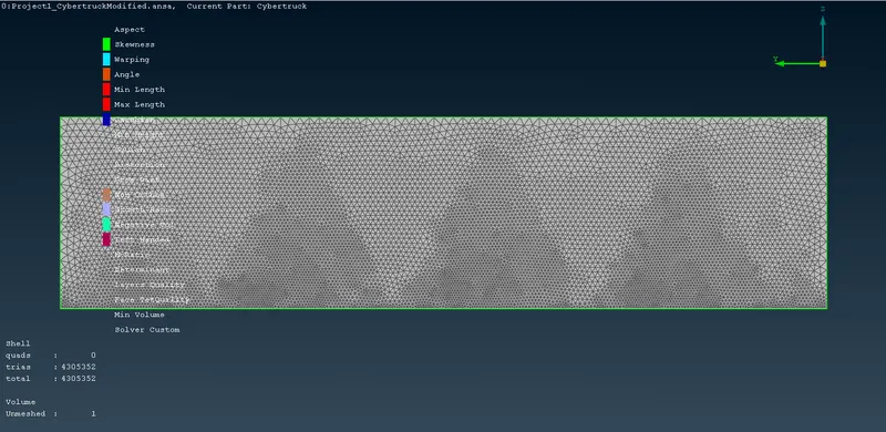
ANSA File for the given Tesla Cyber Truck model after surface meshing and creating Wind Tunnel
https://drive.google.com/file/d/1nncg9rFJLYETpTHFlYRcdKVyubu81Iza/view?usp=sharing