Project 1 : CFD Meshing for Tesla Cyber Truck
https://drive.google.com/file/d/1SBcDQAx5Suo0XAuSAMxfulP27f4hIElv/view?usp=sharing
PROJECT – TESLA CYBERTRUCK
Aim :
To solve all geometrical errors on half portion and assign appropriate PIDs, perform meshing with the given Target length and element Quality criteria. Creating a wind tunnel according to the car dimensions
Procedure : -
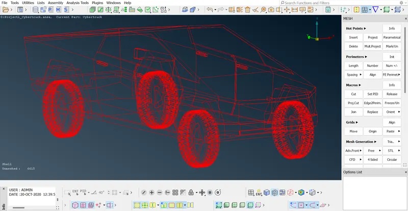
- Open the ANSA model file and check for the geometric and intersection errors
- Hit the TOPO option to see whether it can fix the single cons and solve the errors.
- Divide the car into two equal parts , we can use TRANSFER option and replicate same thing to another by symmetry.
- This makes our work less and more accurate, so delete the one part of the car using UNIVERSAL DELETE option.
- Using PLANE CUT option , select three random points on the model and middle click .
- Now go to LEFT VIEW point and delete the other part of the car.
- Hit TOPO to check autoclear of any single cons.
- Fill the missing faces with NEW option with COONS .
- Check for any geometric and intersection errors using CHECK MANAGER.
- For intersection errors, delete the unnecessary faces and create small faces so that there wont be any intersection of two surfaces.
- After solving intersection errors , again go for errors check for confirmation.
- Thus geometric cleanup can be done.
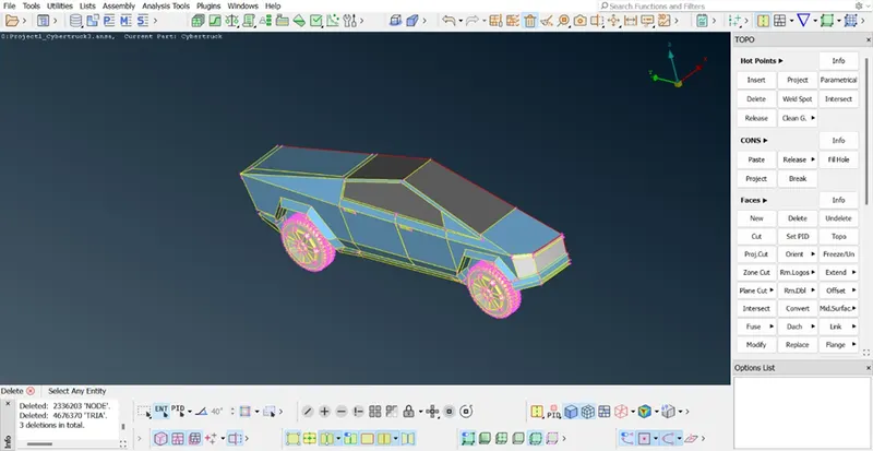
ASSIGNING PIDs AND SURFACE MESHING :
Thus the geometric clean up can be completed we need to assign PIDs to the parts of the car and start surface meshing.
- Open the PROPERTIES MANAGER and we can see many PIDs which are present over there.
- Use COMPRESS option to forcefully delete the unnecessary PIDs.
- Now starting creating new PIDs lights , windows , tyres&rims, and body.
- Start assigning them to the part by right clicking on the PID and selecting APPLY .
- Select the entites which are required and press middle click.
- Repeat the same procedure for each component.
- After completing the assigning PIDs, we can go for meshing.
SURFACE MESHING :
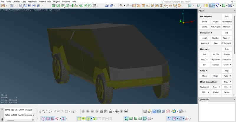
- As we are going for quality criteria , we need to assign some parameters in this model i.e SKEWNESS , MINI LENGTH and MAX LENGTH.
- Make sure that SKEWNESS is 0.5 applied and lengths can be from 0.5 to 6 .
- The mesh lengths for components are :
Lights = 4mm
Body = 3mm
Windows = 2mm
Tyres = 2mm
- Now isolate the one part of the car i.e Grills using OR option , assign the mesh parameter ranging from 0.5 to 2.
- Its always preferable to start meshing the parts from the small rang to high range for good meshing.
- Go to MESH and long press on SPACING option , select AUTO CFD.
- Assign the mesh parameters to MACROS and PARAMETERS.
- Now mesh the part using CFD VISIBLE option.
- Check for many off elements in the component by enabling HIDDEN option .
- If there are any off elements , right click on it and select RECONSTRUCT option .
- Run it and we can see many of the off elements are done.
- For remaining off elemenst , we can use MOVE option in the GRIDS section to remove those elements.
- After finishing this , make sure to freeze the component and for preventing unmeshing surfaces after FULL MESHING.
- Repeat the same procedure for each and every component of the car.
- Thus surface meshing of the car is finished .
SYMMETRY :
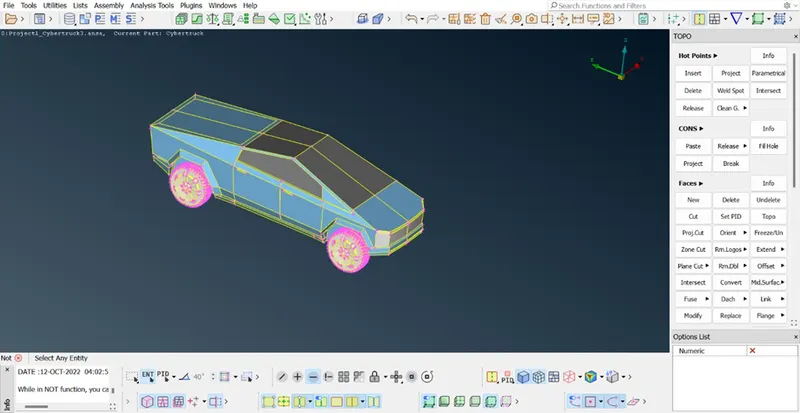
- Now we need to replicate to other part of the car so we need to use TRANSFER option.
- Click on transfer option and select COPY .
- Select the all the entities of the car and middle click.
- A dialgoue box appears, go to SYMMETRY section and select MIRROR 3 POINTS plane .
- Select three hot points of the car from one end to another end .
- Click apply and finish .
- Thus mirroring of the car can be done.
- Now again go for error check and hit TOPO for autoclearing.
WIND TUNNEL :
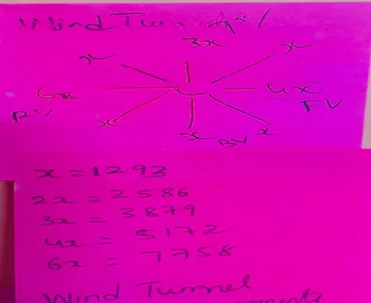
- We need a create a wind tunnel to do a external flow analysis and keep the car inside it.
- For that we need measurements of the wind tunnel , for that we choose the parameters which are present in the above figure .
- Fo creating this wind tunnel we need a reference point, so use RELATIVE option in the curves section .
- First create a point in the bottom of the car , select the middle hot point and distance of 1500 mm in required direction.
- Now taking this point as reference , we can create base surface and do offset to create top surface.
- Measure the distance from the refernce point to front part of the car and also length of the car using MEASURE option.
- Now create a point in the front portion of the car with the value of (4x of car length + distance from reference point to front portion of the care)
- Repeat the same procedure for rear and side parts of the car with respective measurements provided based on the above figure.
- Now using OFFSET option we can replicate same surface above the car with the value of ( 3x of car length + car height ).
- Using FACE option with COONS selection , create new faces around the formed surfaces.
- Assign PIDs to the created surfaces with new names and apply them on to the wind tunnel using PROPERTIES MANAGER.
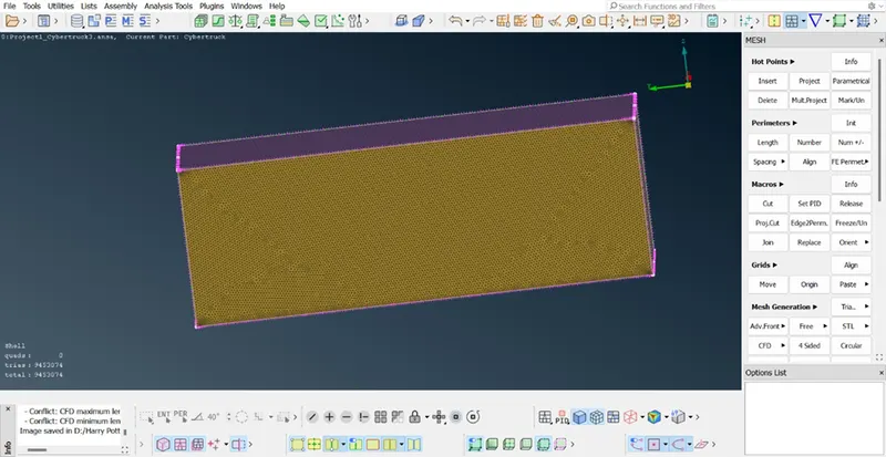
VOLUMETRIC MESHING OF WIND TUNNEL :
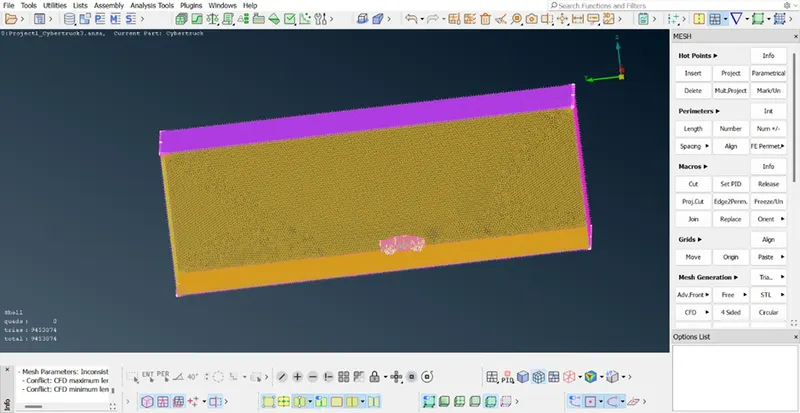
- Go to MESH section , we can omit Quality Criteria for wind tunnel and assign length parameters ranging from 250 to 350
- For top surface and bottom surfaces targeted lengths are 350 and 250 mm respectively.
- Go to SPACING option and assign AUTO CFD lenth parameters.
- Now select CFD VISIBLE MESH.
- Repeat the same procedure for bottom surface too.
- Now coming to rear and side surfaces, we need to do GEOMETRIC MESH ranging from 250 to 350 with length factor of 1.2 apart .
- Go to SPACING,select MANUAL and give GEOMETRIC MESH ranging from 250 to 350 with length factor of 1.2 apart .
- Thus surface meshing can be completed.
- Now go to VOLUMES section, select DEFINE option with wholedatebase parameter.
- This auto generates the volumes present in the model.
- If there are any duplicate elements or volumes , autofix them .
- Now select the require volume from the created volumes and edit mesh criteria.
- Select TRIADS and CFD mesh .
- Now right click on the volume and select REMESH.
- Thus Volumetric Meshing can be completed.
CONCLUSION :
Thus the given car model can be meshed for external flow analysis with the help of wind tunnel.