Project 1 : CFD Meshing for Tesla Cyber Truck
Project 1: CFD Meshing for Tesla Cyber Truck
AIM:
For the given model, check and solve all geometrical errors and Assign appropriate PIDs. Perform meshing with the suitable Target length and element Quality criteria.
GIVEN MODEL:
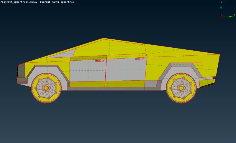
Side View
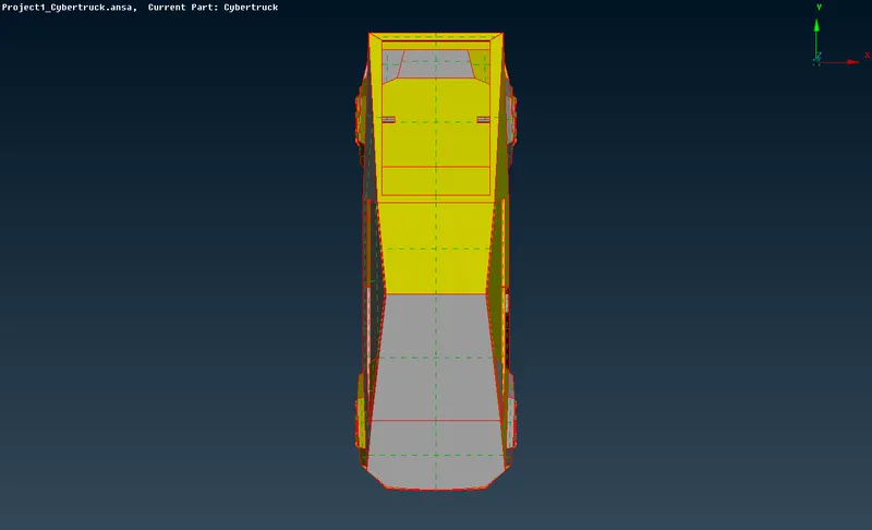
Top View
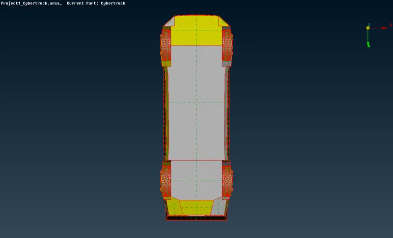
Bottom View
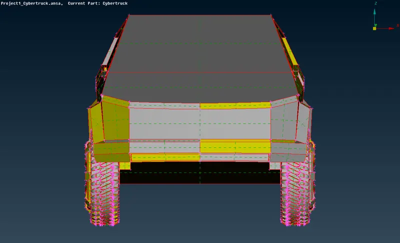
Front View
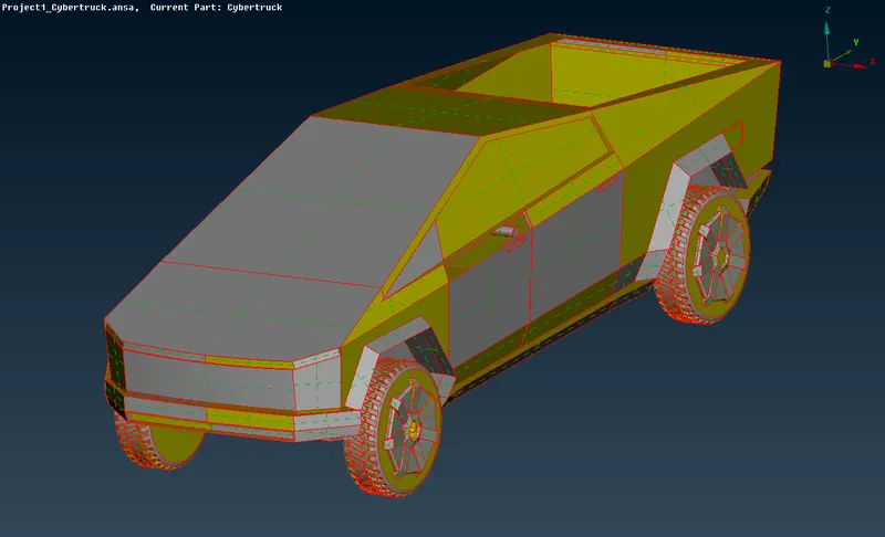
Isometric View
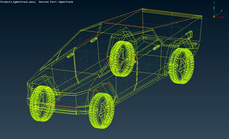
Unshadowed Iso-view
Procedures before TOPO:
- We have to make the resolution of the cons finer than in the given model, for that, we are meshing the model using the length option of 1mm.
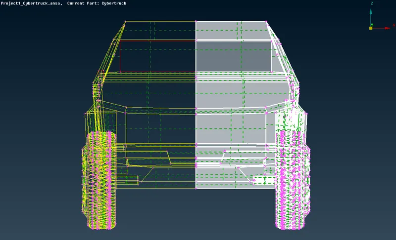
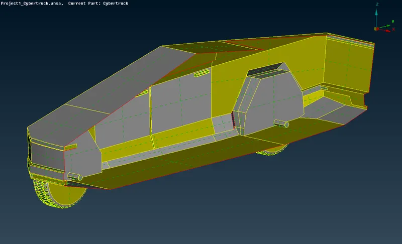
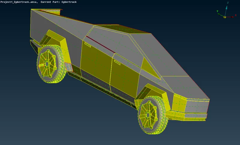
- Before we get into TOPO cleaning procedure, we have to slice the geometry into two parts in their symmetrical plane, since they are symmetrical in nature also.
- On completing all the procedures in one half of the model, we can make a copy of this half into the other easily at last.
- To cut the geometry we are deleting one half of the potion with many errors. (excluding logo since it is not symmetrical).
- Before doing these steps we have to make our geometry symmetrical, to do these we are cutting the surfaces symmetrically.
- The procedures are shown below pictures.
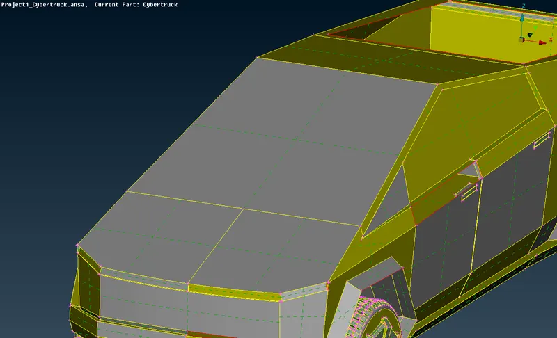
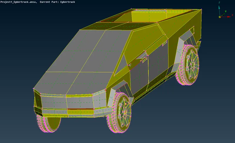
- Use the delete option to delete one-half of the model.
TOPO Cleanup Procedure:
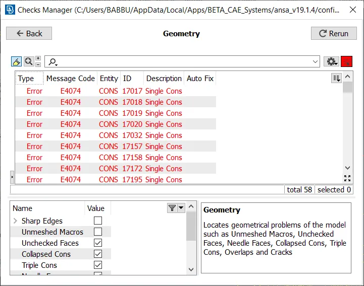
- As we see the model given has many single cons, we want to do some Geometry checks to explore what are the errors we are encountering here,
- SINGLE CONS- the edge which is shared by only one surface.
- DOUBLE CONS- the edge which is shared by two surfaces.
- TRIPLE CONS- the edge which is shared by three surfaces.
- And the model has some overlapped surfaces which have to delete to reduce the error during the meshing process.
- We have to check the triple cons also, in which region they are needed or not.
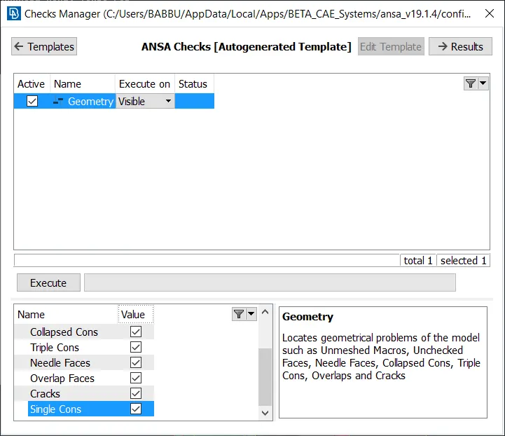
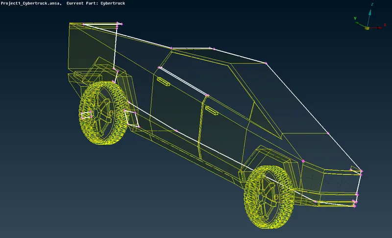
While performing a geometry check in the given geometry, we are getting multiple errors such as triple and single cons, overlapping surfaces as we discussed above,
- And the errors are highlighted in white color as shown in the below picture.
- As we have to remove the errors from the geometry to proceed with the meshing process, we have multiple tools to do so.
- First, we will see, how to delete the overlapped surfaces.
- Use the universal delete option to delete the surfaces.
- Enable the cross-hatches option in the geometry to select the surface easily which we want to delete.
- Use the PIDs selection tool to select a complete region in one shot, after selection delete the overlapped surface, as shown in the below pictures.
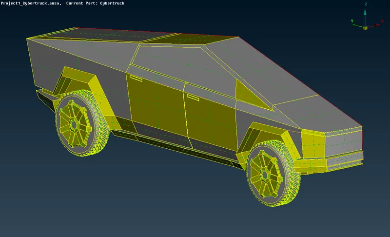
- After completed with the TOPO clean up the geometry is shown below,
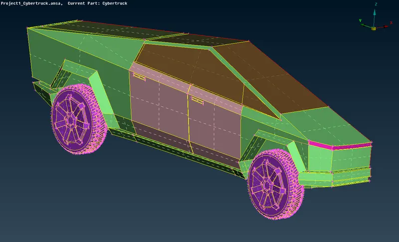
- After this step, we are flagging the appropriate boundaries to the respective regions as shown below,
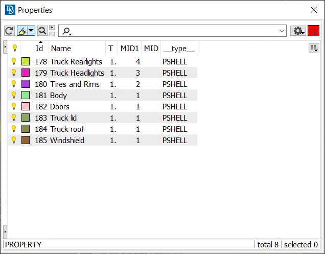
- After given the boundaries we are meshing the geometry with the given mesh lengths.
- The meshed Geometry is shown in the below picture,
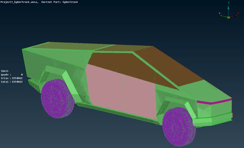
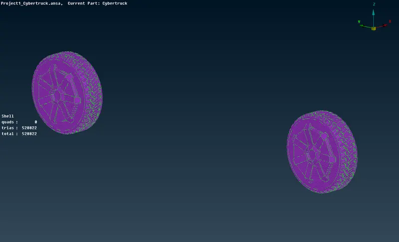
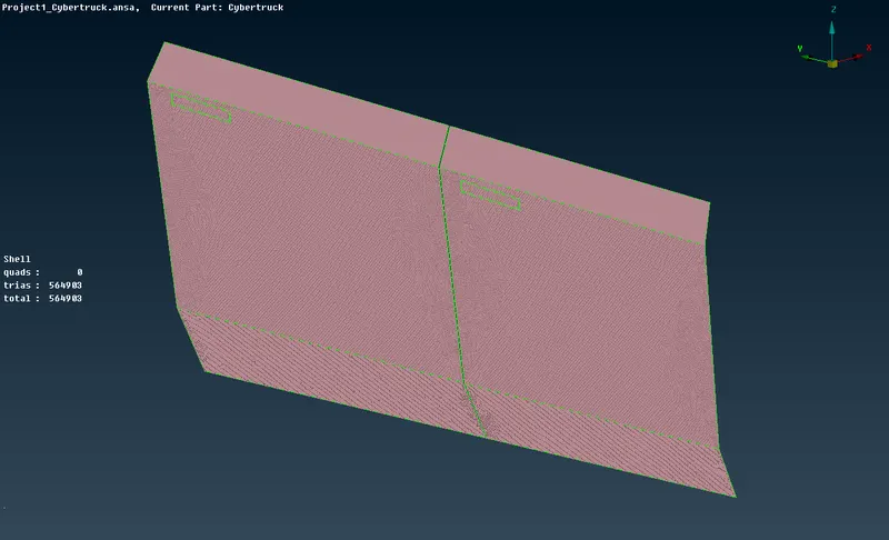
The mesh generated on the truck body:
a. Tires and Rims:
b. Doors:
c. Truck roof and trunk lid:
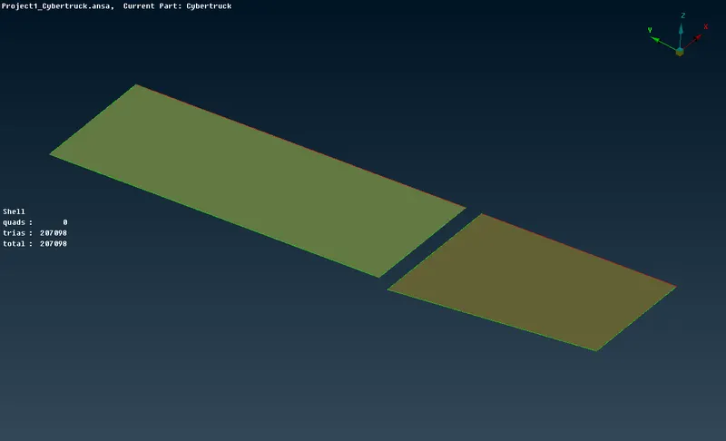
d. Truck Headlights:
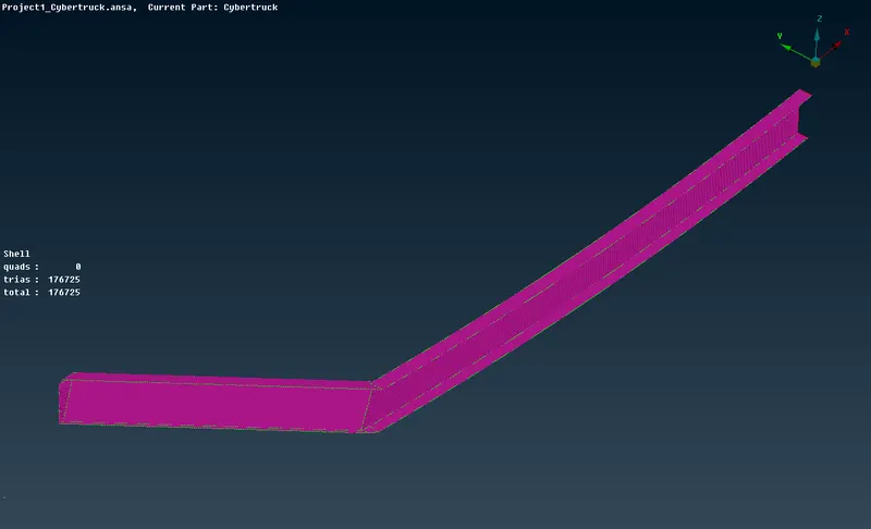
e. Truck Rear lights:
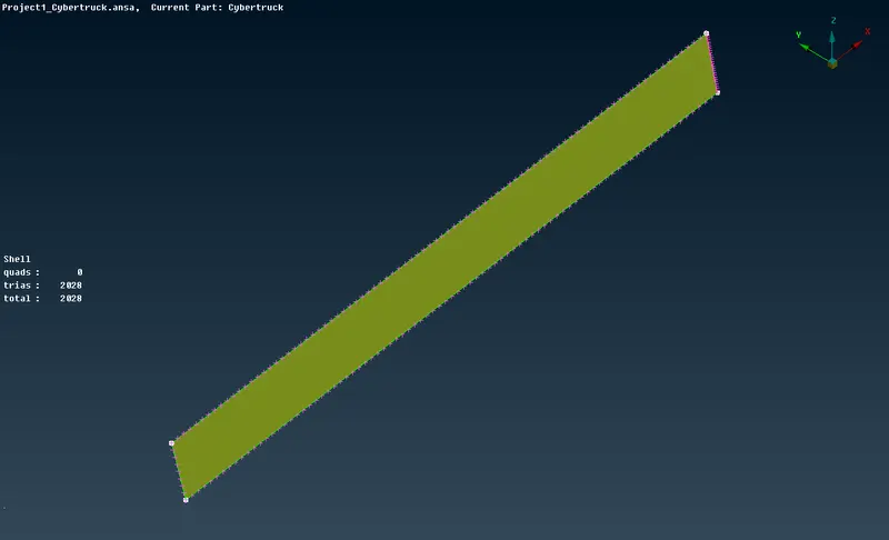
f. Windows:
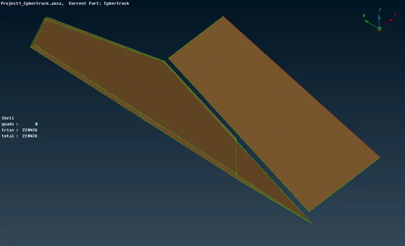
e. Truck body:
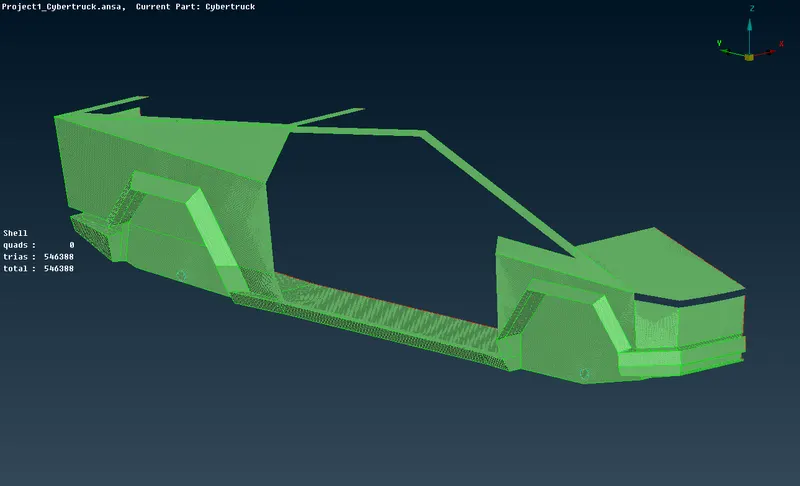
- Once the mesh is generated on all the regions of the truck, we can now generate the complete truck model.
- This is done by the use of the symmetry option. Transform> copy> entities> symmetry> mirror 3 point plane, then select any 3 points on the symmetric plane.
- Once this is done, all the entities will get copied to the other side of the symmetric plane.
- The geometry may show some single cons once this is done, this can be rectified by performing topological checks. Topo> faces> topo.
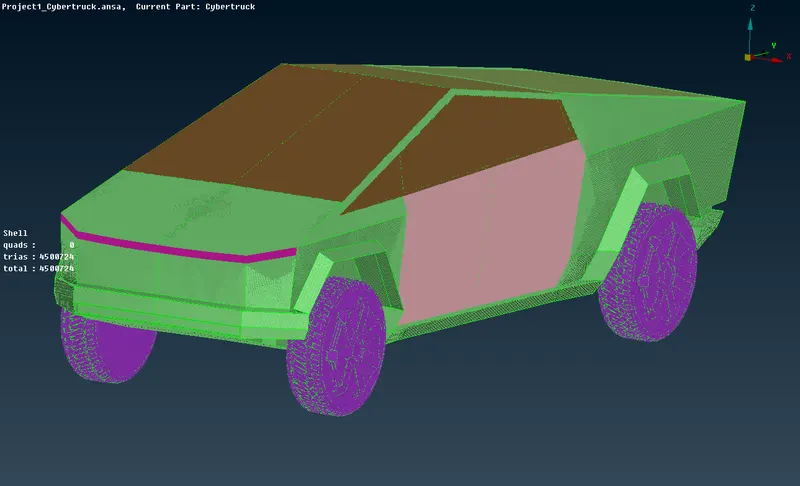
- Once this is done, the truck geometry must be enclosed in a box (virtual wind tunnel) to perform external aerodynamic simulations. If the length of the car is 'L' meters then, the virtual wind tunnel dimensions are as follows:
a. Distance from the wind tunnel inlet to the front of the truck= 4L
b. Distance from the aft of the truck to the wind tunnel outlet= 6L
c. Distance from the sides of the truck to its respective wind tunnel sides= L
d. Distance from the floor to the top surface of the wind tunnel= 3L
- The virtual wind tunnel is created by first, identifying the origin of the global coordinate system, then, the location of wind tunnel floor corners is calculated and points created, these points are joined with curves.
- There must be a minimal gap between the tires and the wind tunnel floor to simulate the aerodynamic flow over the truck accurately.
- A face can be created from these curves. To get the top surface of the wind tunnel, a copy of this face is offset at a distance of 3L.
- The side faces and the inlet and the outlet of the wind tunnel can be created by using the reference of the wind tunnel top surface and floor cons.
- Now a surface mesh must be generated on the wind tunnel surface.
- Since we want finer volume mesh near the surface of the car, which is resting on the floor of the wind tunnel, we must provide a smaller mesh size for the wind tunnel floor and a larger mesh size on the wind tunnel top surface.
- The mesh size on the sidewalls and the inlet and the outlet of the wind tunnel must increase gradually from the floor to the top surface of the wind tunnel.
- To achieve this first the wind tunnel floor and top surfaces are meshed separately with triad mesh elements and the mesh target length of 20mm and 100mm respectively.
- Now, to mesh the other faces in a gradually increasing manner, go to mesh> perimeters> spacing, select the 4 edges, take biasing as geometric (1.1), and dmin= 20, dlimit= 100.
- Next, mesh the geometry using spot mesh, and check for quality criteria errors if any. If there are any errors, it can be rectified mesh> shell mesh> reconstruct.
The mesh quality criteria for the wind tunnel is as follows:
Mesh generated on wind tunnel walls:
a. Windtunnel floor:
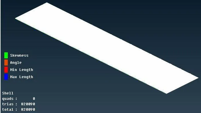
b. Windtunnel top surface:
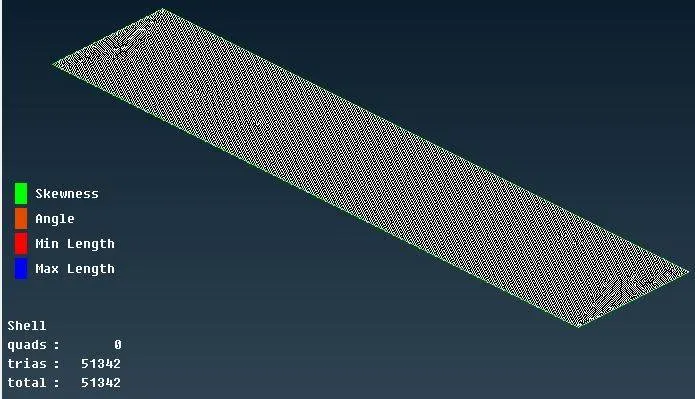
c. Windtunnel side walls:
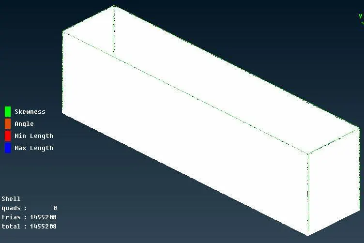
- Once the surface mesh is generated on all the components, the volumetric mesh can be created.
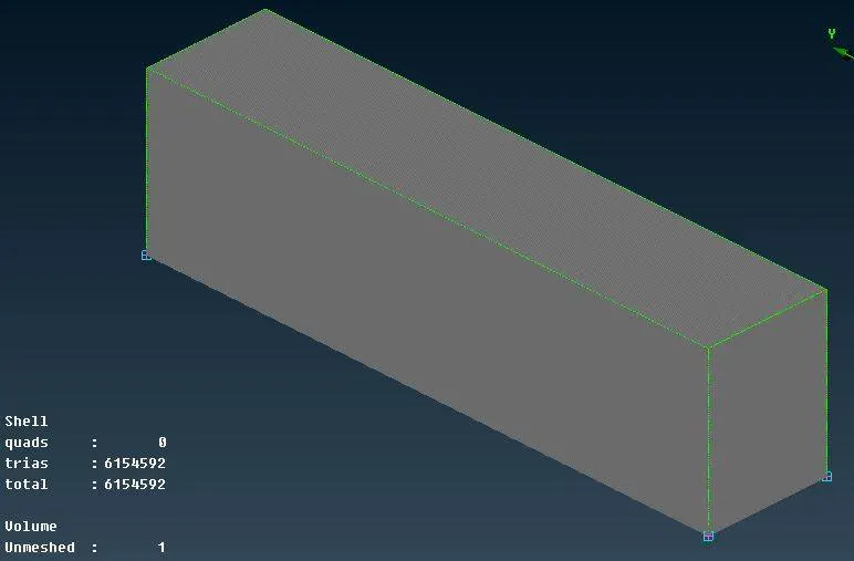
- In volume mesh> define> auto-detect> whole data base.
- Here, delete all the unwanted components, ie, the volumes enclosed by the solid surfaces (in this case 4 tires and 2 silencers).
- Now right click on the fluid volume detected and click on re-mesh using tetra CFD mesh, and the required mesh will be generated.
- Generating the volumetric mesh requires a lot of computational power and storage, hence, it cannot be performed on a general-purpose laptop. It can be performed easily on more powerful multi-processor systems.
Conclusions:
Hence, the surface mesh was generated on the car body and on the wind tunnel surface with the set mesh quality criteria and mesh target lengths.