Project 1_Analyze and design a steel building to 10T CRANE as per IS standard code using TEKLA STRUCTURAL DESIGNER.
AIM:- The aim of this project
- Analyze and desingn a steel building to 10cT CRANE as per IS standard code in TEKLA STRUCTURAL DESIGNER. Refer tthe attached plan and elevation. Provide bracings and moment connection for lateral stability.
- Considere dead, live , equipment and wind loading. Consider the brick wall loading for 150mm thick and 1.5KN per sqm for wall and roof cladding.
- Assume wind loading basic speed as 39m/s
- Report of each member to be generated and extract drawing of structural plans from the softtware
INTRODUCTION:
Tekla structural Designer is used for analysis and design of structures. Thefirst step is to model the structure, then to apply dead load , live load , seismic load over it and to study the response of the structure. The response of the structure can be its deflection, shear force or bending moment. Accordingly suitable measures are taken for increasing the member size,providing UB/UC beams, restraining top flange continuity etc. Finally all the members are checked for failures
PROCEDURE:
- Study the drawing of structural layout
- Launch TSD
- Save the new files as project-1
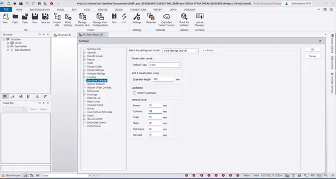
- Now go to Home tab-settings to check units,Design codes, Structure defaults etc.
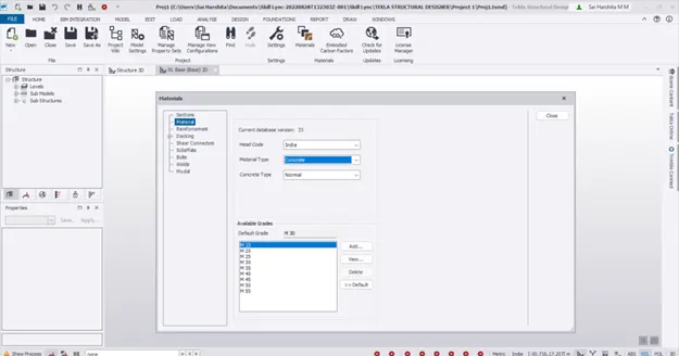
- Also go to the home - materials to check the material grades
Construction Levels:
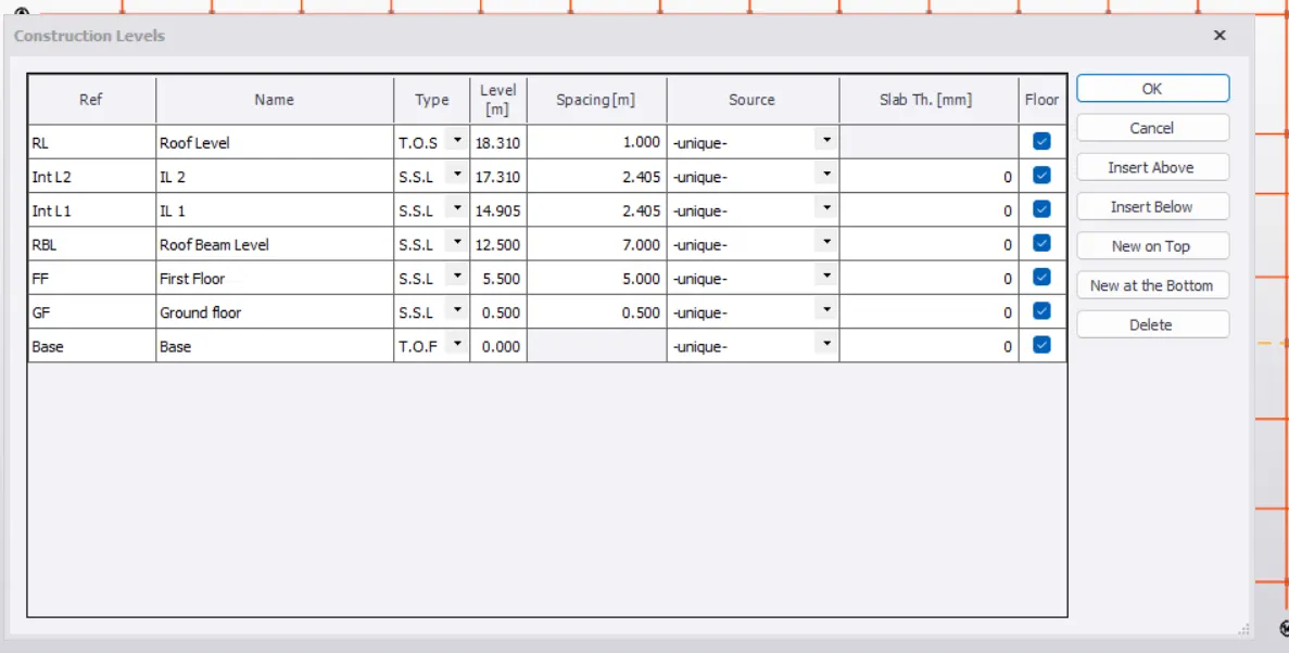
- Go to model- construction levels
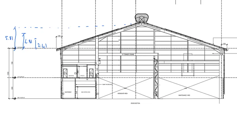
- Study the section details to enter height of GF,FF,RBL and RL
- To find the height of roof level assume roof angle as 17deg
- tan 17= Height of the roof/ (span/2) = H/(38000/2)
- Therefore, H= tan 17*19000 = 5808mm =5.808m
Grid Lines:
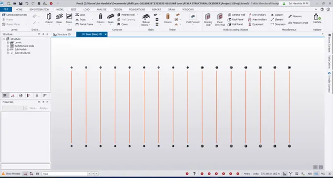
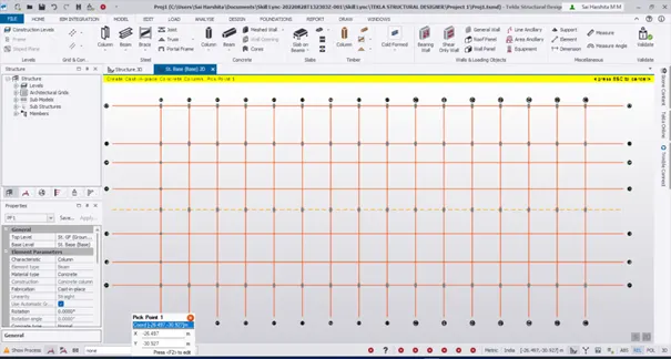
- Go to model -Grid lines
- Draw 16 vertical grids 6m spacing
- Number it accordingly
- Similarly construct the horizontal grid lines A-G of appropriate spacing as given in the layout
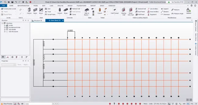
Pedestals:
- Check the drawing to see wheter any construction lines are neede to model the pedestal
- Draw a construction line of 14m from B using paralle (quick) in the construction line option
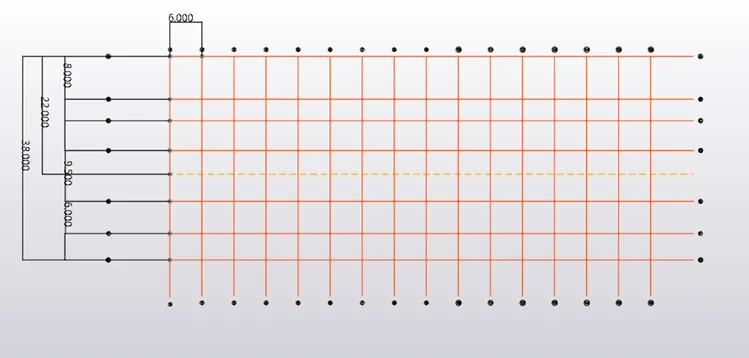
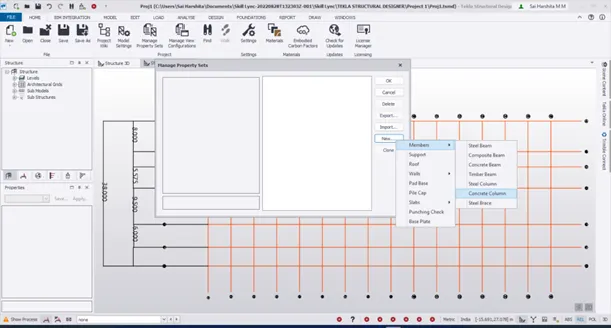
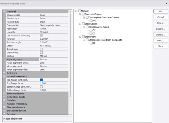
- To create pedestal, go to Home - Manage property sets- New members- Concrete column
- Create a pedestal of size 500*1000mm, majaor alignment- center and release - fixed top and bottom
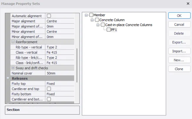
- Under Moadel- concrete - column, pick Pf1 from the properties windows and start placing the columns
- Select the levels as Base level to GF level
Modeling steel Columns:
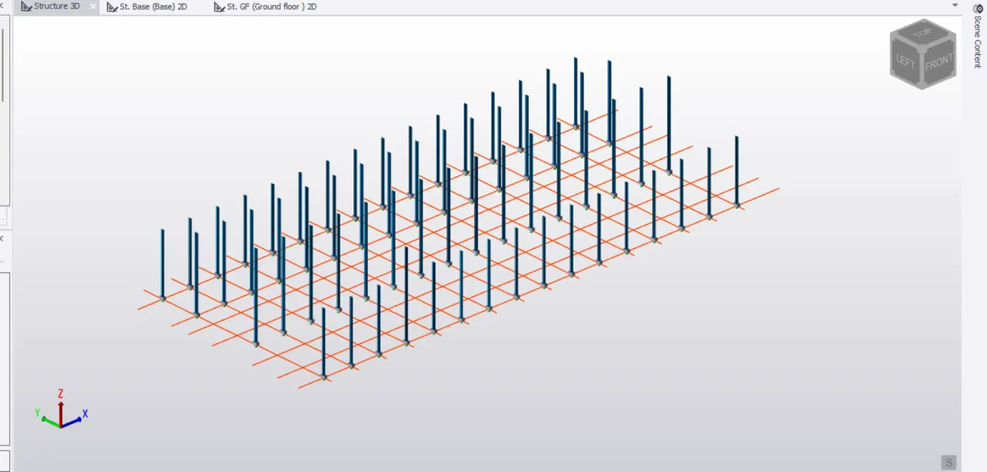
- Check the section layout drawing.Notice that the interior columns are of different heights
- So create 2 additional levels next to RB level. As we have set the roof level at 5.81m from RBL subtract 1m for the roof level =4.81m
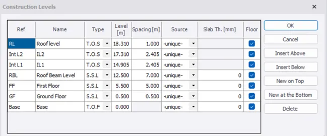
- Model the steel column of ISMB 550
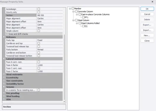
- Now go to GF level
- Click on steel - column
- From the properties, choose C1 (MB 550) and then the levels from GF level till the roof beam level for outer grids and C2(MB 600), levels from GF to Int L1 for grid B and levels from GF to Int L2 for columns on construction line
Modeling Steel Beams
- Create a beam B1 of MB 550, alignement - bottom, center for GF and top, center for other floors
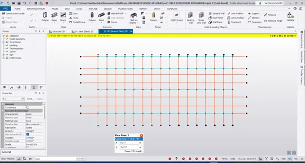
- Model B1(MB 550) beam for all 6m span
- Create another beam B2 MB 600 for beas between A and B grids
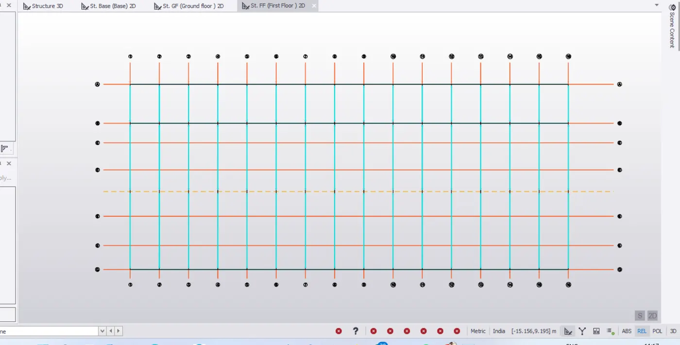
- Model B3 MB 350 for secondary beams connecting primary beams
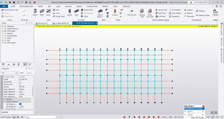
- Now model beams for staircase
- Draw a grid line 3m from the 9th grid to model staircase beam
- Now coming to the first floor, check the layout
- Notice that there are no intrmediate beams between B and G
- So we need to model the beams accordingly
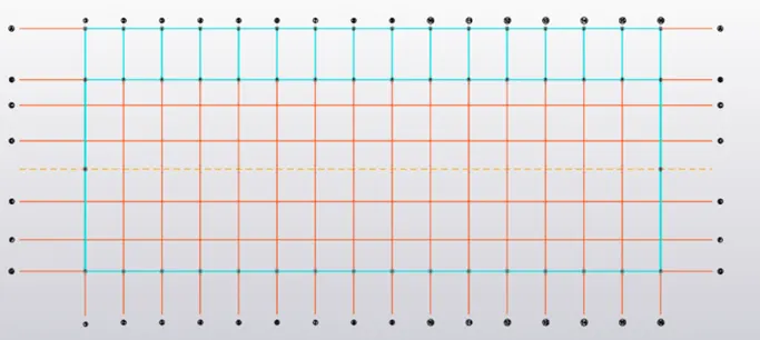
- Model secondary beams between A and B
- Similarly model staircase beams between grids 9 and 10
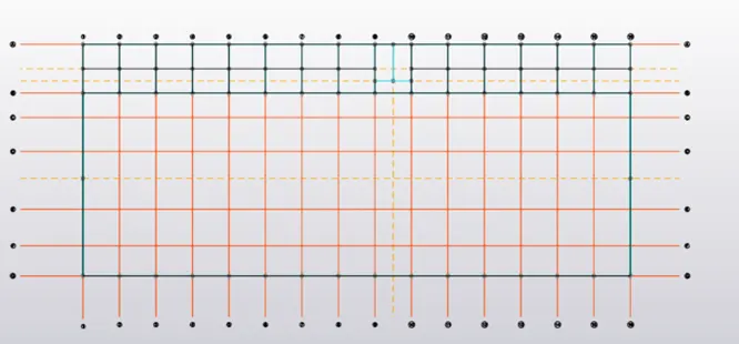
- Similary proceed the roof level
Frame modeling:
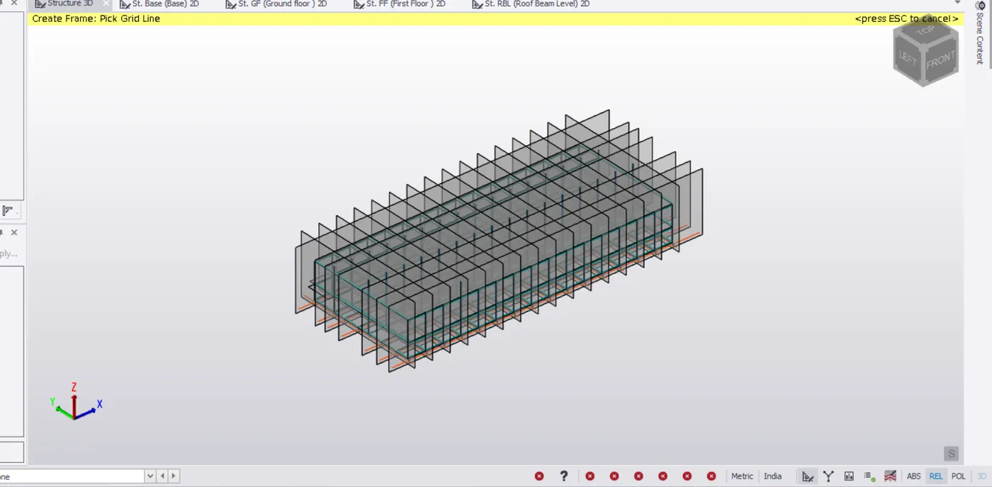
- Inorder to create rafters, frame modeling needs to be done
- Go to model - frame and pick all grid lines
Creating Rafters:
- Model the grid line at the midspan(38000/2 =19000) for the apex of the rafter
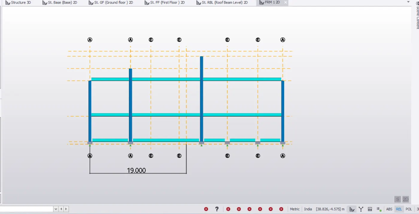
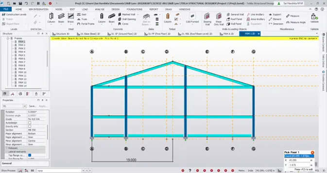
- Then go to structure 3D to Edit - copy rafter to all frames by picking the reference node
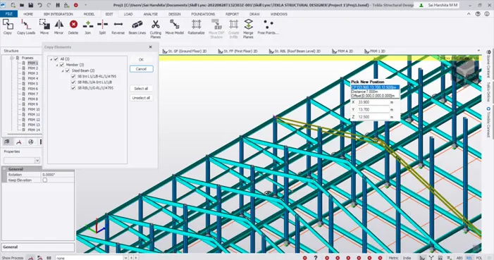
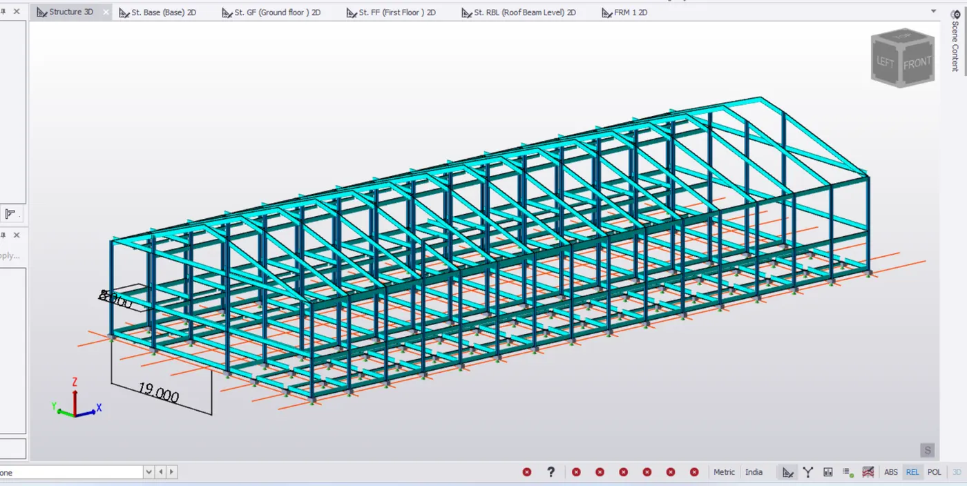
- Now provide the ridge beam connecting the apex of all rafters
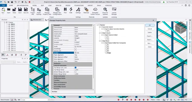
- Also model purlins by using ISMC section
Modeling Bracings:
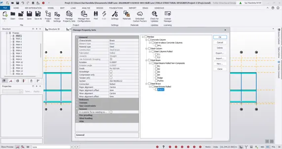
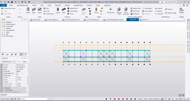
- Similarly model bracing for roof also
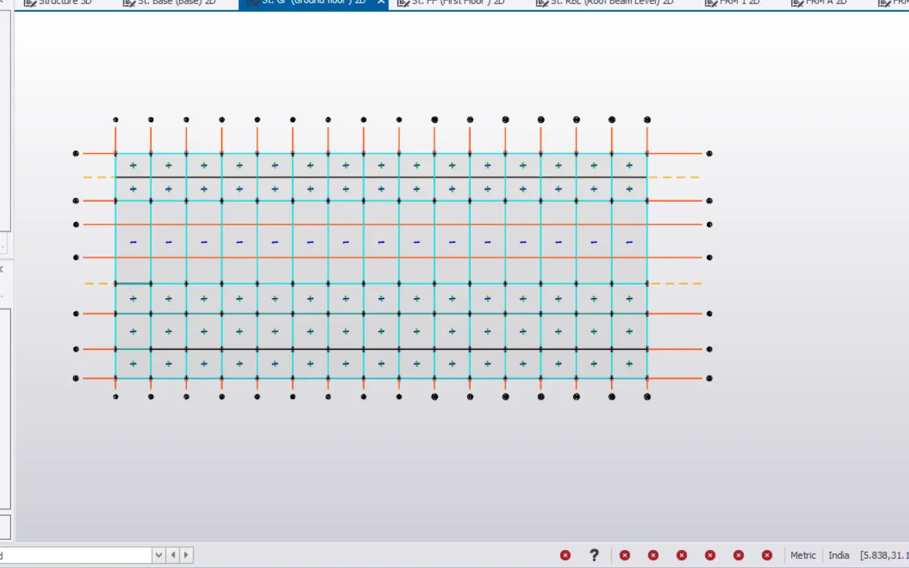
Creating slab on beams:
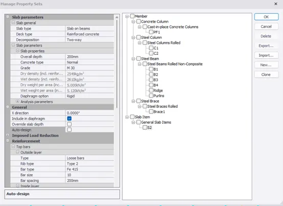
- Find ly/lx ratio and classify the slab as either one way or two and assign accordingly
- Create Slab S1(one way) and S2(two way) with the following properties
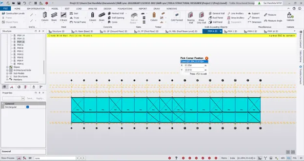
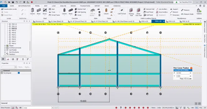
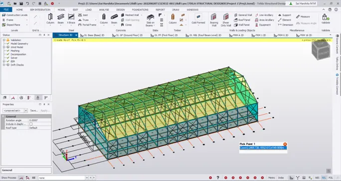
Creating wall and Roof panel:
- Selecting frame A and G frame 1 and 16 to model the wall panels
Bracket for crane support:
- On checking the section drawing, brackets are placed at 950+2050 from the FF level
- So we need to create a construction level at 3000mm from the FF level
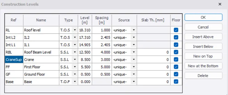
- Now go to Crane support level and draw a panel construction line 1m from gridline B.
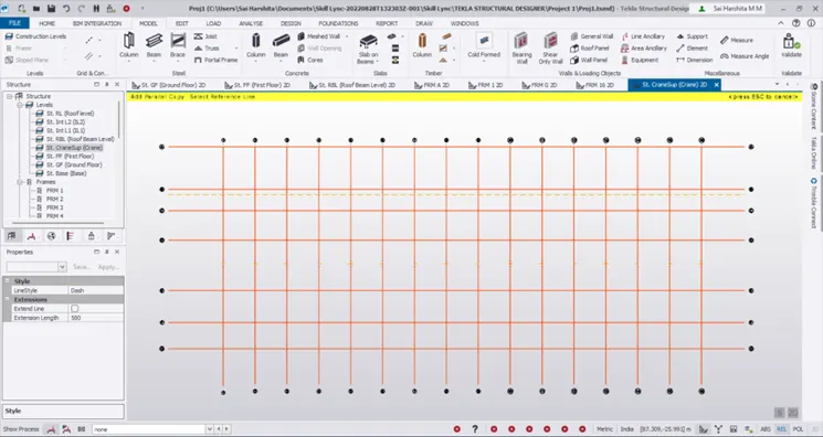
- A cantiliver beam of MB 550 is to modelled as teh bracket supporting the crane
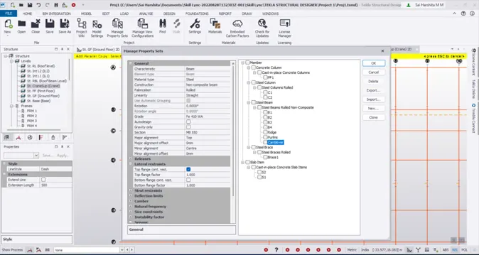
- Now model this beam from grid B to the construction line.
- Notice that it throws an error on validating.
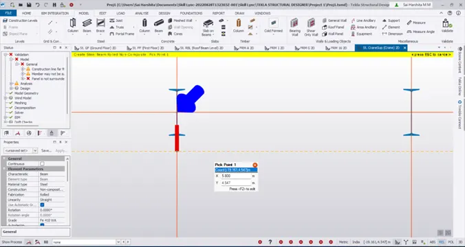
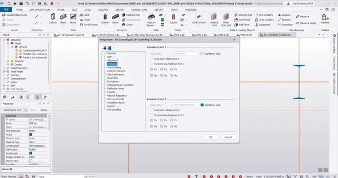
- Double click on the beam to change its properties
- Mark releases at end 2 as cantiliever end
- Copy and paste the brackets to other grid lines
- Mirror the brackets to the construction line draw parallel to the grid
Application of loads:
Dead load application:
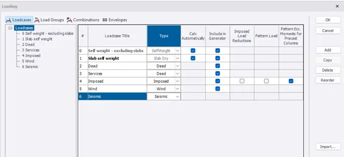
- Under load cases, add wind and seismic loads
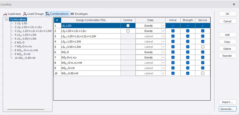
- Under combinations, select Generate to generate the load combinations
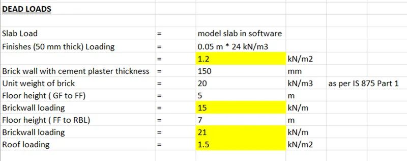
- Lets now proceed with Dead load calculations by opening a MS Excel file and calculating floor finishes load, Brickwall load (from GF to FF to RBL) and roof loading
- Let's now go to GF level to apply these loads
- Under loadcases below, select Dead load
- Now we are going to apply the floor finish load of 1.2KN/m^2 to each slab
- Select Area load under panel loads
- Change the load intensity to 1.2KN/m^2 and select each panel one by one
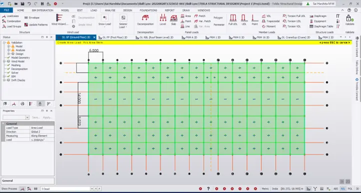
- Similarly apply the floor finishes load of 1.2KN/m^2 to the other floor also
- Validate the model for any errors
- Check the applied dead loads in 3D view
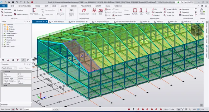
- Now the brickwall loading is applied for each floor by reffering to the sketches
- For the GF level, brickwall loading of 15KN/m is applied
- The loading is first applied along the perimeter
- Under member laods, select Full UDL for the brick walls according to the sketch
- Repeat the same procedure for FF level too
- Now apply the roof loading of 1.5KN/m^2
LIVE LOADS APPLICATIONS:
- Referring to IS 875 part 2 , the following table is framed
- The various rooms in our structure are listed one by one
- The correspoinding live loads are obtained from the IS 875 part 2 code book
- Now select Imposed load from the load cases below
- Go to panel loads - Area loads /patch to apply loadings on flooring referoing to the sketch
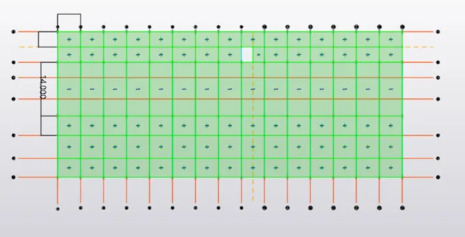
- Apply the roof loading of 0.75KN/m^2 on the RB level
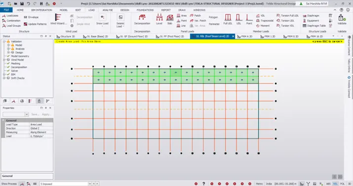
Crane Load:
Now lets generte a calculationn for 10T crane loadign based on following inputs
- Crane capacity =10T = 10000Kg=100KN
- Center to center of wheel = 14m
- Weight of crab =40KN
- Total Number of wheels =4
- Wheelbase =2m
- No of wheels on each side =2
- Weight of the crane =60KN
- Span of the gantry girder (max c/c distance between 2 columns)6m
Maximum Wheel load:
There are 2 loads acting on the crane girder.
- UDL due to self weight of the Crane
- Concentrated loads due to weight of thecrab/ trolley and crane capacity (Weight lifted by the hook)
Lets find the loads one by one.
UDL due to self weight of the crane = S.W crane /c/c between the wheels
= 60/14 = 4.3KN/m
Concentated load due to weight of the crab/ trolley and crane capacity = 40+100 = 140KN
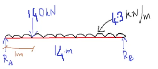
Minimum hook apprach = 1m
Applyinng the equilibrium equations,
Ra+Rb = 140+(4.3*14*7)=0
RA= 160KN
RB =200-160 =40KN
Max reaction is taken always
Ra =160KN = static wheel load
This load is shared by 2 wheels, load transferref by 1 wheel = 160/2 =80KN
Adding 25% for impact = 100KN
Factored load =100*1.5=150KN
Maximum Bending Moment:
Assume self weight of the gantry girder =1.6KN/m
Self weight of the rails =0.4KN/m
Total UDL =1.6+0.4 =2KN/m
For maximum BM, the wheel loads should be kept so that the C.G of 2 wheel loads and the wheel loads recline equidistant from the centre of the span
i.e Max BM occurs under wheel loads 'a' when center of the span is at equal distance from the wheel load and the C.G of the wheel loads
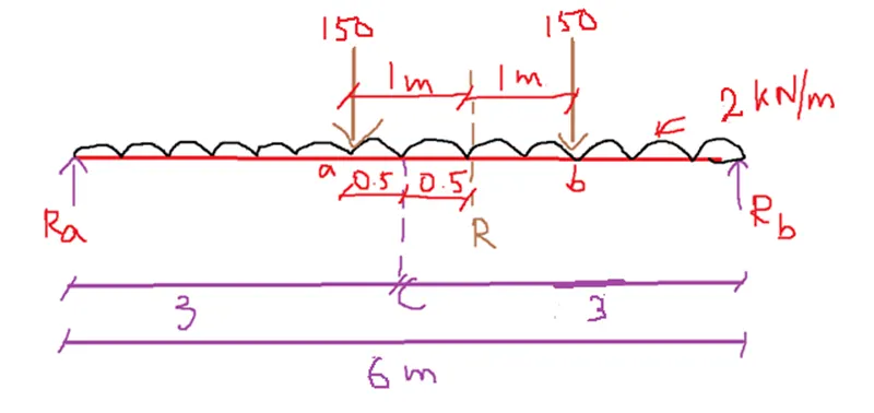
Ea at B =0
(6*ra)-(150*6)-(150*)-(2*6^2/2)
Ra =256KN
Lateral force:
Surge load along y =10% of (crane capacity+crab load)=0.1*(100+40)=14KN
This load is shared by 4wheels =14/4 =3.5KN
Finding the BM for this load,
150-a 321.25KN/m
3.5-a(3.5*321.25)/150 = 7.5KNm
Brake load along x = 5% of static wheel load = 0.05*160=8KN
- Now lets apply the crane load in the form of nodal loads on the brackets
- (Brake, surge,max SF) are choosen as (x,y,z) loads repectively
- In our case, it is (8,14,256)
- First create a crane load case from load - Loadcase option
- Under the construction level crane supp and load case as crane, go to load - Member loads -Point loads
- Under load type choose nodal load and enter (x,y,z) load values as (8,14,256) KN respectively
- Pick the nodes in the brackets
- Thus the crane loads are applied as nodal loads on the brackets
Wind Load:
- Given, basic wind speed, Vb=39m/s ; Terrain category =2
- Length of the building , l =90m
- Breadth of the building w=38m
- Height of the building h=18.31m
Step1: Finding Design wind speed
- Refering to IS 875 p3, vz = vb k1,k2,k3,k4 according to c1 6.3
- Where vz - Design wind speed
- K1 - Probability factor
- k2 - terrain roughness and heigth factor
- k3 -topography factory
- K4 - importance factor for cyclonic region
From table -1 , K1 =1
From table-2, for height of the building 18.31 and terrain category 2 k2 obtained by interpolation.
- For 15m, K2 =1.05
- For 20m , k2 =1.07
- Therefore, for 18.31m k2 = 1.063 = 1.06
- From C1 6.3.3 , K3=115 for industrial structures
- Substitung all the above, Vz =39*1*1.06*1*1.15 = 47.54m/s
Step 2 :Finding Design wind pressure:
From C1 7.2 wind pressure, Pz = 0.6Vz^2
Pz = 0.6 * 47.54 62 1356.1N/m^2
Pz=1.356 KN?M^2
Pz= 1.356 KN/m^2
Step 3: Design wind pressure:
Wind Load wall
- From c173.1 F= (Cpe-Cpi)Apz = Cp*pz
- Cpe is found from Table 5 of IS 875 p3 for h/w and I/w ratios
- h/w = 18.31/38 = 0.48
- I/w = 90/38 = 2.37

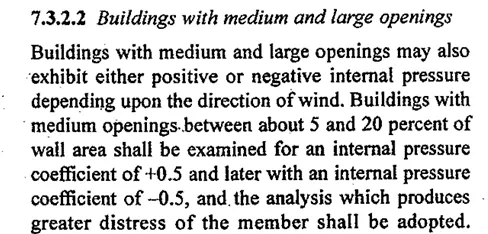
- Let's consider medium openings in which coi = +0.5/-0.5 according to CI 7.3.2.2 of IS 875 part 3
Wind angle 0:
A- windward side, D - leeward side
Lets consider th loding wind+Y+cpi, Wind+y-cpi for all four sides A,B,C and D
Wind angle 90:
C - windward side, D - leeward side
- Lets consider the londing wind+ci, wind +x+cpi, wind +x-cpi for all four sides A,B,C and D

Wind Load on Roof:
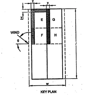
- For calculation win load, h/w ratio angle is required to find cpe
- In our case, roof angle =17deg
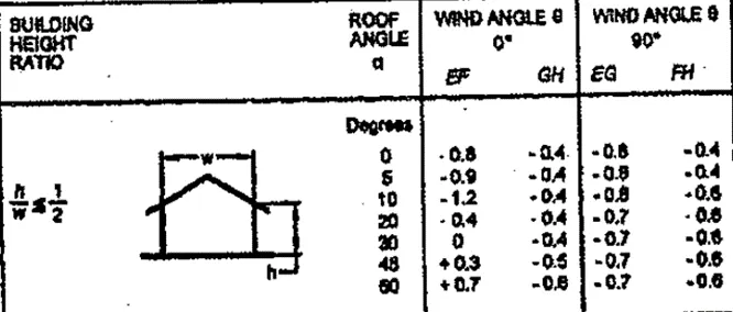
For a roof angle of 17 deg, we need to interpolate between 10 and 20
Wind angle 0, EF = -0.64, GH = -0.4
Wind angle 90, EG =-0.75, FH= -0.6
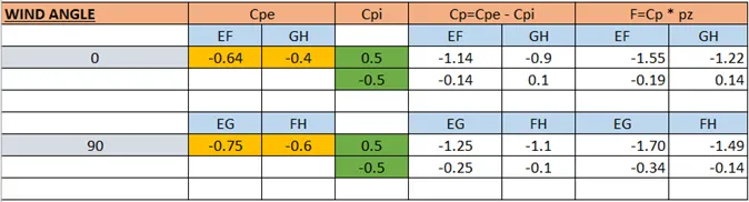
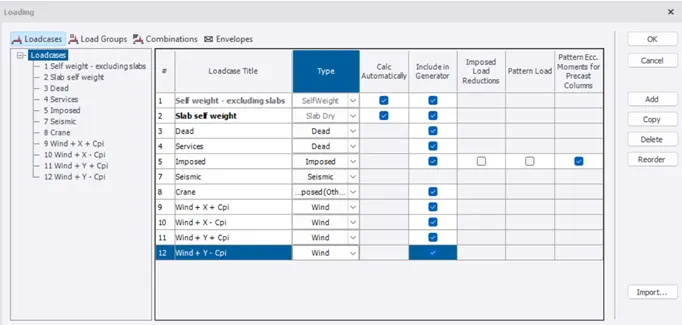
- Go to Load cases to add the wind load cases in X and Y directions for +cpi and -cpi
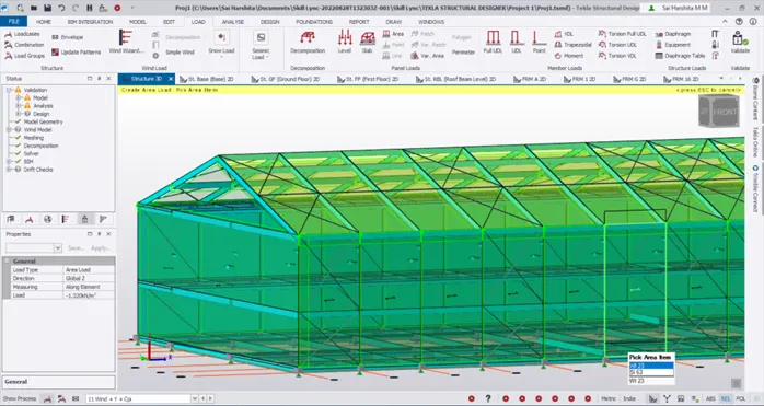
Wind+ y+cpi:
ON Walls:
On Roofs:
Wind+Y-cpi:
On walls:
On Roof:
Wind+x-cpi:
On walls :
On Roofs:
Sesimic Load:
- Under Load -seismic load - Seismic Wizard
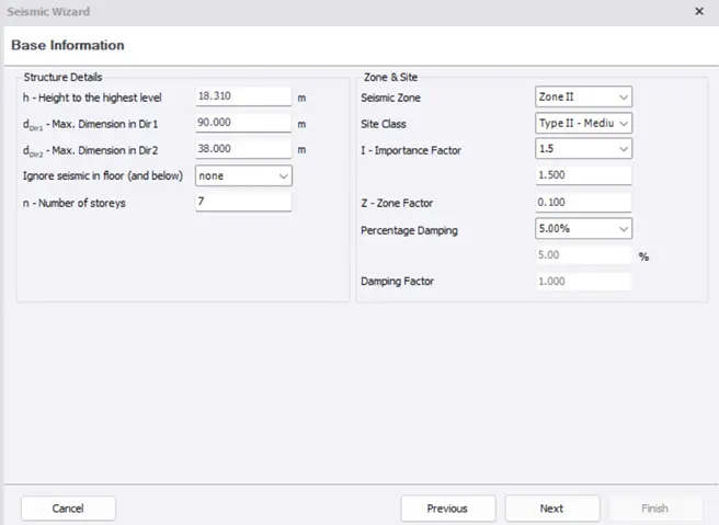
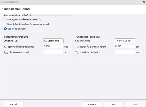
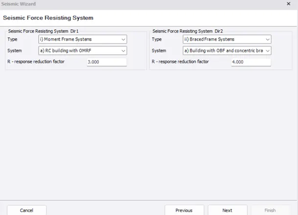
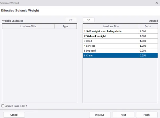
- Now the load combinations are generated
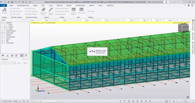
Validate the model and then run analysis
ANALYSIS:
- Analyze -1st order linear
- Select load combinations
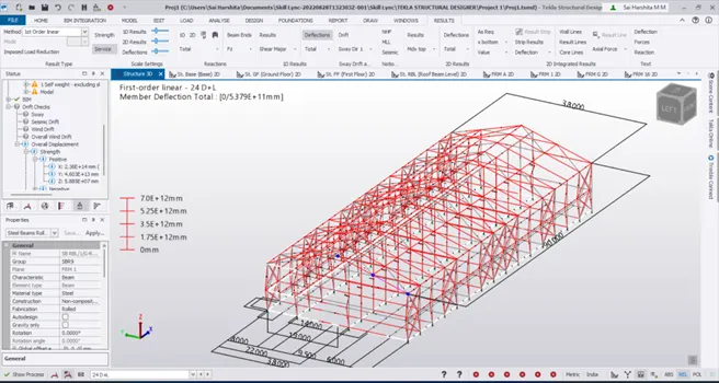
- Under Drift checks, check for deflection
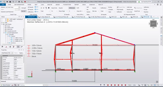
- Notice that all maximum deflections happen in the brackets where cranes are resting
- So we need to incerease the member size of the bracket and column supporting brackets
- Also note that we have very high deflection in the columns and rafter. So increasing their member size is also important.
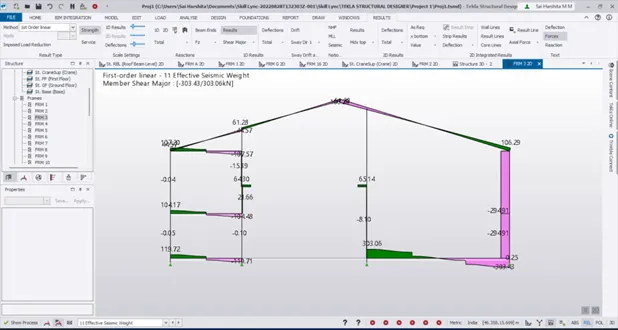
- The BMD of a frame is as follows,
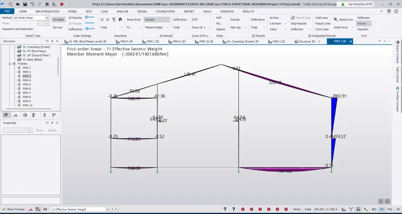
- The SFD is as follows
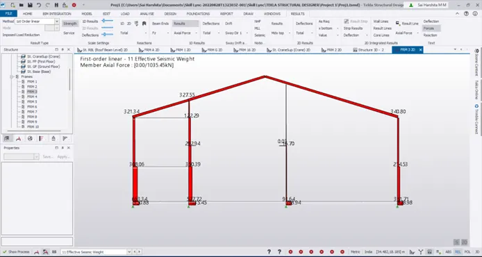
- The AFD is as follows,
- So now lets increase the member sizes and reanalyze the model
- First of all lets increase the size of the rafter and help it pass the design criteria
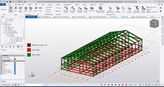
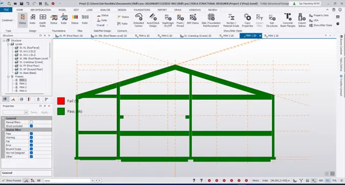
- Lets pick frame by frame an select all the member to understand how many members have passed/failed accordingly redesign the failed members Select all the members of the frame and check the section
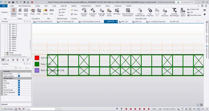
- select FRM G
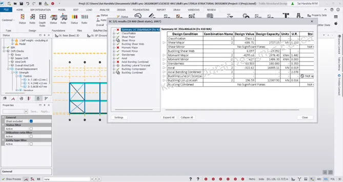
- Check from frame 1 to 16
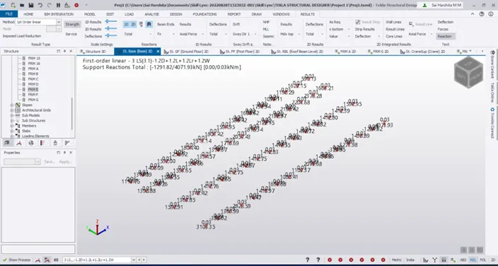
- Check the support reactions
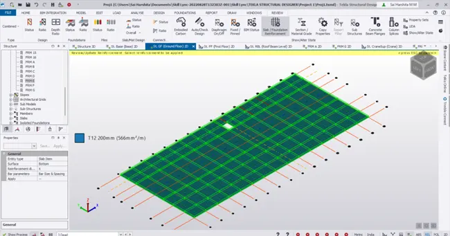
Slab Design:
- Go to Review at the bottom in GF
- In the scene content hide, steel columns, beams, bracing, concrete column
- Select slab/ foundation reinforcement
Pad footing:
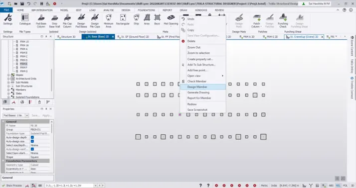
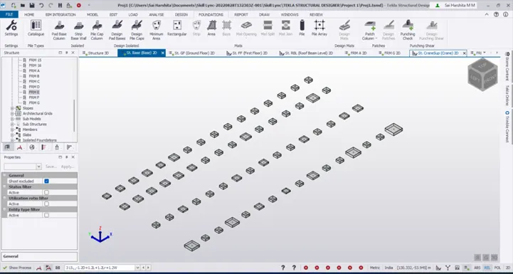
- Go to Base levle
- Under on any support to place the footing
- Click on any support to enter the details of top bars just enter type as loose bars bar diameter will be automatically designed
- Right click on the created footing and select Design member The footing size and the diameter of the bar used will be designed automatically
Result:
Thus a thorough analysis and design of a industrial structure has been carried out by following the below steps:
- Modelling grids lines
- Modelling pedestals for the base floor
- Modelling steel columns from the ground floor
- Modelling steel beams (primary and secondary )
- Modeling brackets for crane support
- Modelling rafter and purlins
- Modelling bracings
- Modelling wall and roof panels
- Applying live loads to each floors
- Applying crane loads
- Applying wind loads in both X Aand Y direction
- Generating seismic loads
- Generating load combinations
- Running the analysis
- Checking the deflection
- Identifiying the failed members and suitably adjusting the sized of them
- Slab reinforcement design
- Footing design