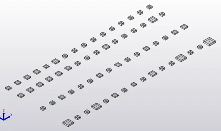
Project 1_Analyze and design a steel building to 10T CRANE as per IS standard code using TEKLA STRUCTURAL DESIGNER.
AIM:
The aim of this project is to,
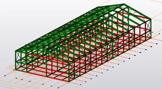
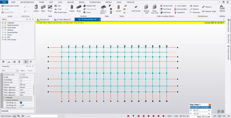
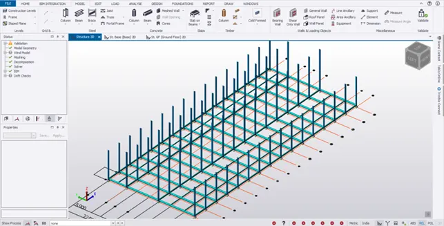
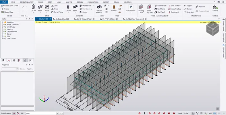
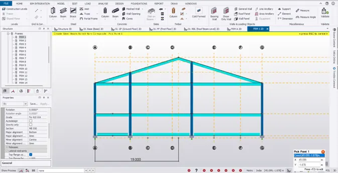
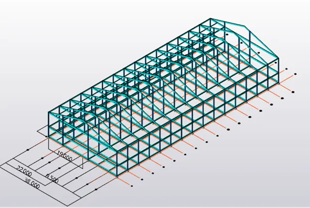
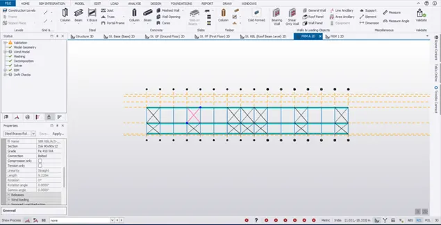
- Analyze and design a steel building to 10T CRANE as per IS standard code in TEKLA STRUCTURAL DESIGNER. Refer the attached plan and elevation. Provide bracings and moment connection for lateral stability.
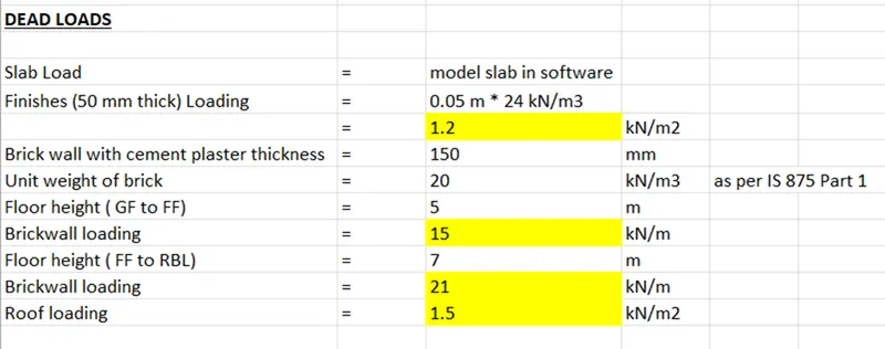
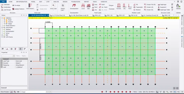
- Consider dead, live, equipment and wind loading. Consider the brick wall loading for 150mm thick and 1.5 KN per sq m for wall and roof cladding.
- Assume wind loading basic speed as 39m/s
- Report of each member to be generated and extract drawings of structural plans from the software
PROCEDURE:
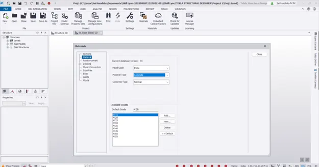
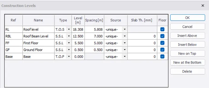
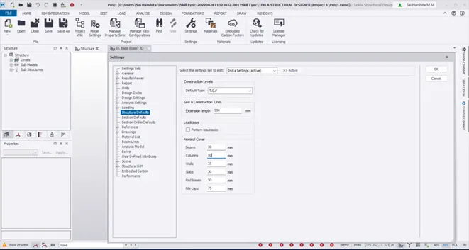 s
s
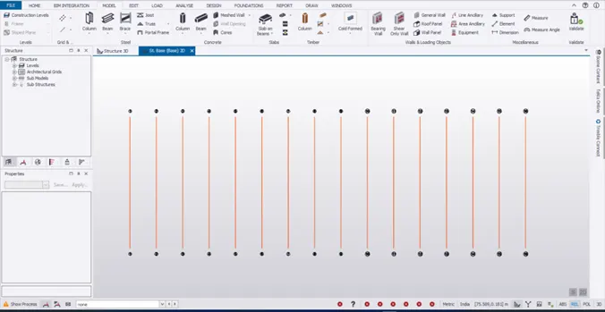
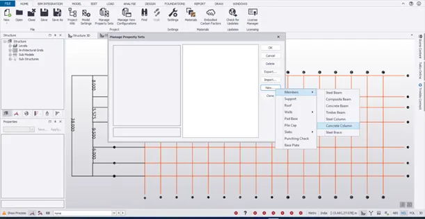
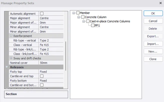
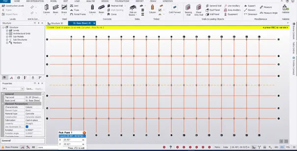
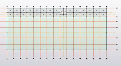
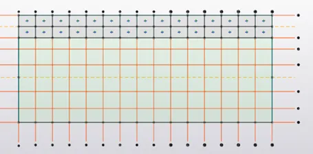
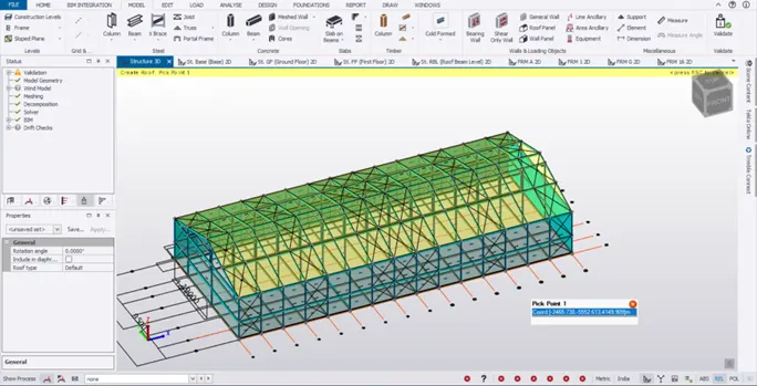
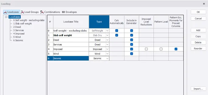
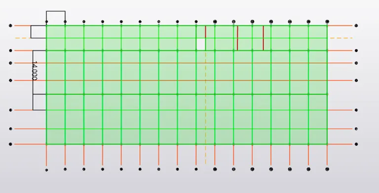
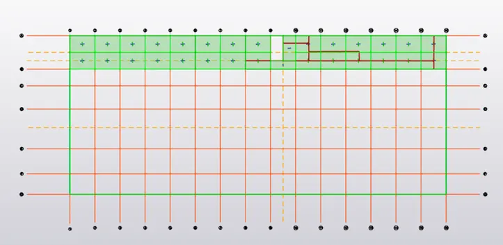
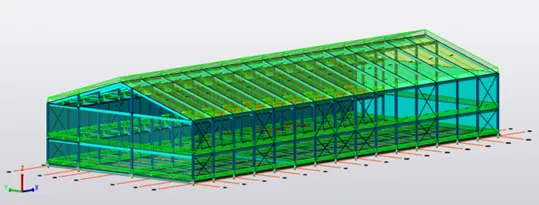
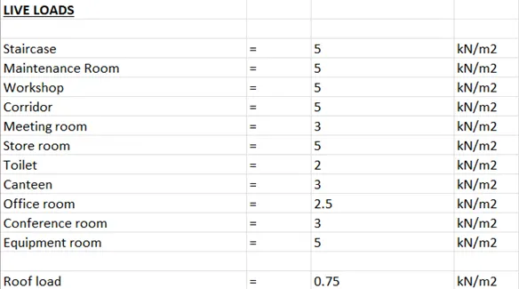
Live Loads Application:
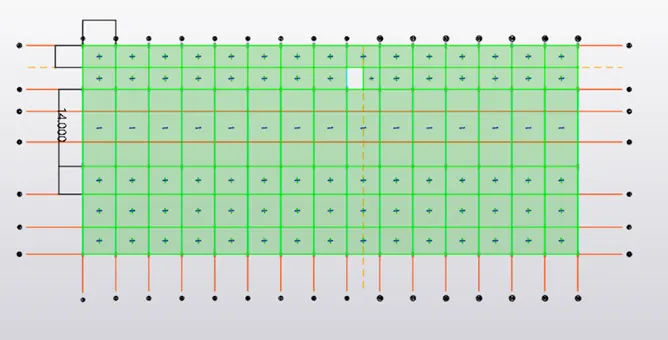
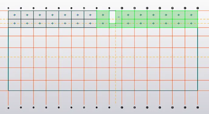
- Referring to IS 875 Part 2, the following table is framed
Crane Load:
Now lets generate a calculation for 10T crane loading based on following inputs
- Crane capacity = 10T = 10000kg = 100 kN
- Centre to Centre of wheel = 14m
- Weight of crab = 40 KN
- Total Number of wheels = 4
- Wheel base = 2m
- No of wheels on each side = 2
- Weight of the crane = 60 kN
- Span of the gantry girder(max c/c distance between 2 columns) = 6 m
Maximum Wheel load:
There are 2 loads acting on the crane girder.
- UDL due to Self weight of the crane
- Concentrated load due to weight of the crab / trolley and crane capacity(weight lifted by the hook)
Lets find the loads one by one.
UDL due to Self weight of the crane = S.W of the crane / c/c between the wheels
=60/14 = 4.3 kN/m
Concentrated load due to weight of the crab / trolley and crane capacity = 40 + 100 = 140 kN
Minimum hook approach = 1m
Applying the equilibrium equations,
Ra + Rb = 140 + (4.3* 14) = 200 kN
∑M b = 0
(14 * Ra) – ( 140 * 13) – ( 4.3 * 14 * 7) = 0
Ra = 160 kN
Rb = 200 – 160 = 40 kN
Max reaction is taken always
Ra = 160 kN = Static wheel load
This load is shared by 2 wheels , Load transferred by 1 wheel = 160/2 = 80 kN
Adding 25% for Impact = 100 kN
Factored load = 100 * 1.5 = 150 kN
Maximum Bending Moment:
Assume self weight of the gantry girder = 1.6 kN/m
Self Weight of the rails = 0.4 kN/m
Total UDL = 1.6 + 0.4 = 2 kN/m
For maximum BM, the wheel loads should be kept so that the C.G of 2 wheel loads and the wheel loads recline equidistant from the centre of the span
i.e Max BM occurs under wheel load ‘a’ when centre of the span is at equal distance from the wheel load and the C.G of the wheel loads
Ra + Rb = (150 *2) + (2 * 6) = 312 kN
∑M at B = 0
(6 * Ra) – (150 * 1.5) – (150 * 3.5) – (2 * 6 * 6/2 ) = 0
Ra = 131 kN
Rb = 181 kN
Max BM at a = (131 * 2.5) – (2 * 2.5^2/2) = 321.25 kNm
Maximum Shear force in gantry girder:
For the max SF in gantry girder, one of the wheel loads have to be placed on the support
∑M at B = 0
(6 * Ra) – ( 150 * 6) –(150 * 4) – (2 * 6^2 / 2) = 0
Ra = 256 kN
Lateral force:
Surge load along y = 10 % of (crane capacity + crab load) = 0.1 * (100 + 40 ) = 14 kN
This load is shared by 4 wheels = 14 / 4 = 3.5 kN
Finding the BM for this load,
150 -à 321.25 kNm
3.5 -à ( 3.5 * 321.25) / 150 = 7.5 kNm
Brake load along x = 5 % of static wheel load
= 0.05 * 160 = 8 kN
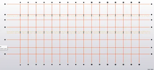
- Now lets apply the crane load in the form of nodal loads on the brackets
- (Brake, Surge, Max SF) are chosen as (x,y,z) loads repectively
- In our case, it is (8 , 14 , 256)
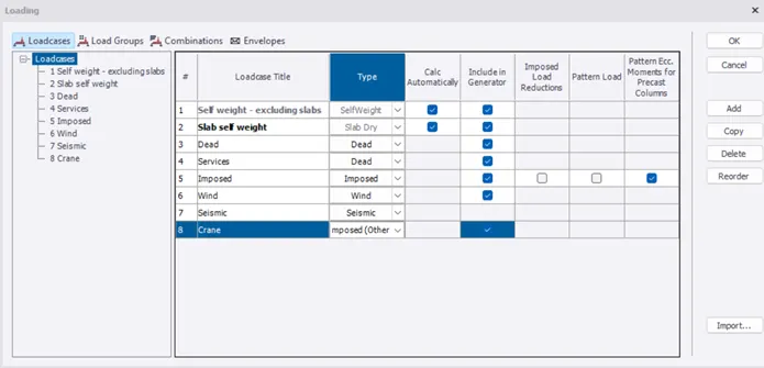
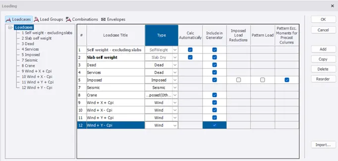
- First create a Crane load case from Load – Loadcase option
- Under the construction level Crane Supp and load case as crane, go to Load – Member loads – Point loads
Wind Load:
- Given, basic wind speed , Vb = 39 m/s ; Terrain Category = 2
- Length of the building, l = 90 m
- Breadth of the building, w = 38 m
- Height of the building, h = 18.31 m
Step 1: Finding Design Wind Speed:
- Referring to IS 875 P3, Vz = Vb k1 k2 k3 k4 according to Cl 6.3
- Where Vz – Design wind speed
- K1 – probability factor
- K2 – terrain roughness and height factor
- K3 – topography factor
- K4 – importance factor for cyclonic region
- From table 1, k1 = 1
- From table 2, for height of the building 18.31 m and terrain category 2 , k2 is obtained by interpolation.
- For 15 m , k2 = 1.05
- For 20 m , k2 = 1.07
- Therefore, for 18.31 m , k2 = 1.063 = 1.06
- From Cl 6.3.3 , k3 = 1 since, theta < 3(flat terrain)
- From Cl 6.3.4, k4 = 1.15 for Industrial structures
- Substituting all the above values, Vz = 39 * 1 * 1.06 * 1 * 1.15 = 47.54 m/s
Step 2: Finding Design Wind Pressure:
- From Cl 7.2, wind pressure, pz = 0.6 Vz^2
- pz = 0.6 * 47.54 ^ 2 = 1356.1 N/m2
- pz = 1.356 kN/m2
Step 3: Design Wind Load:
Wind Load on Wall:
- From Cl 7.3.1, F = (Cpe – Cpi) A pz = Cp * pz
- Cpe is found from Table 5 of IS 875 P3 for h/w and l/w ratios
- h/w = 18.31 / 38 = 0.48
- l/w = 90/38 = 2.37

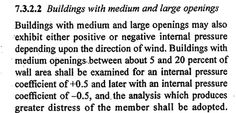
- Lets consider medium openings in which Cpi = + 0.5 / -0.5 according to Cl 7.3.2.2 of IS 875 part 3
Wind angle 0:
A – windward side , B – leeward side
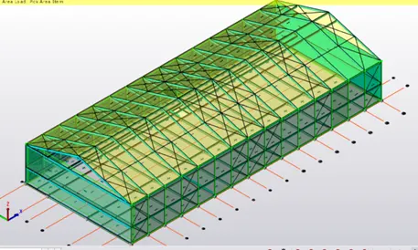
- Lets consider the loading Wind + Y + Cpi , Wind + Y – Cpi for all four sides A, B, C and D
Wind angle 90:
C – windward side , D – leeward side
- Lets consider the loading Wind + X + Cpi , Wind + X – Cpi for all four sides A, B, C and D

Wind Load on Roof:
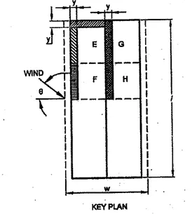
- For calculating wind load, h/w ratio and roof angle is required to find Cpe
- In our case, roof angle = 17 deg
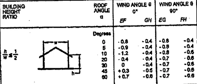
For a roof angle of 17 deg, we need to interpolate between 10 and 20
Wind angle 0, EF = -0.64, GH = -0.4
Wind angle 90, EG = -0.75 , FH = -0.6
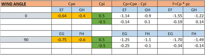
- Go to Load – Load cases to add the wind load cases in X and Y directions for + Cpi and – Cpi
Wind + Y + Cpi:
On Walls:
Wind + Y – Cpi:
On Walls:
Wind + X + Cpi:
On Walls:
On Roof:
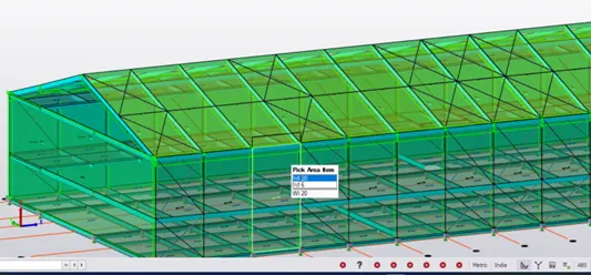
Wind + X – Cpi:
On Walls:
On Roofs:
Seismic Load:
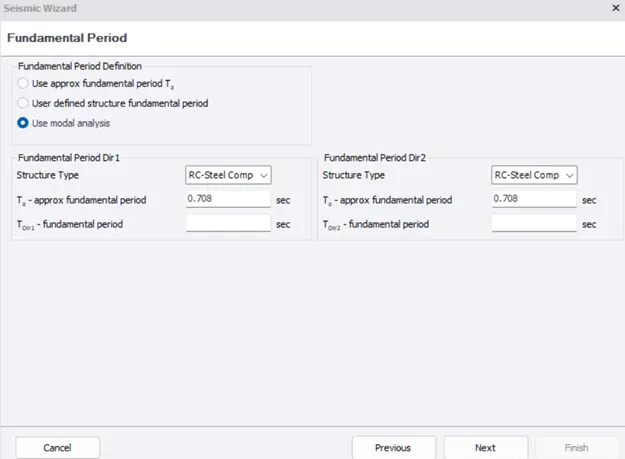
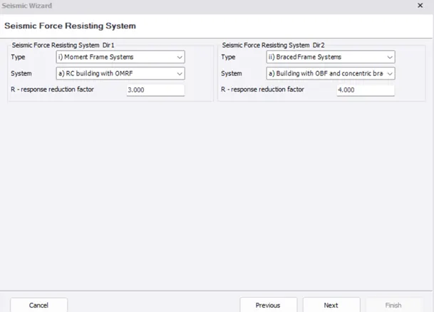
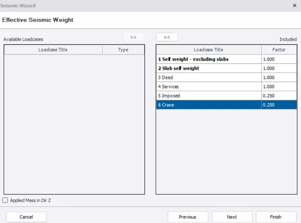
- Under Load – Seismic load – Seismic Wizard
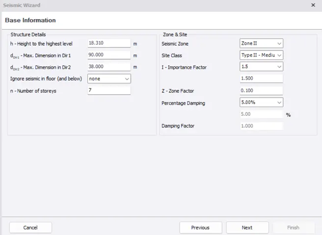
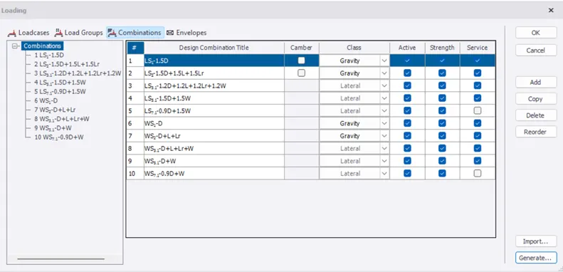
- Now the load combinations are generated
ANALYSIS:
- Analyze – 1st order linear
- Select load combinations
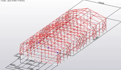
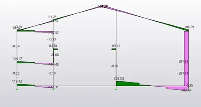
- The BMD of a frame is as follows,
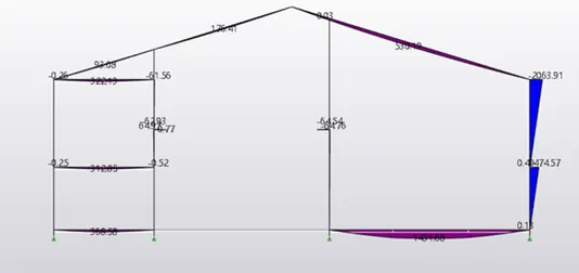
- The SFD is as follows