Designing of plastic component
Designing of plastic component from the given class A surface of a component
Class A surface is the outside surface of a component which is visible to the customer from their naked eye. This surface needs to be aesthetically very good and should not contain any defects.
The procedure followed to make the plastic component from the input class A surface are:
1. Import class A surface into the work space
2. Determination of tooling axis for the class A surface
3. Creation of class B surface
4. Creation of flanges
5. Creation of class C surface
6. Creation of closed surface by combining class A, class B, class B and flanges.
7. Draft analysis on the plastic component
1. Importing class A surface
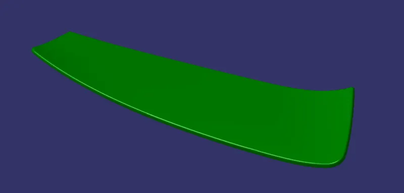
The class A surface used to make the plastic component is shown below:
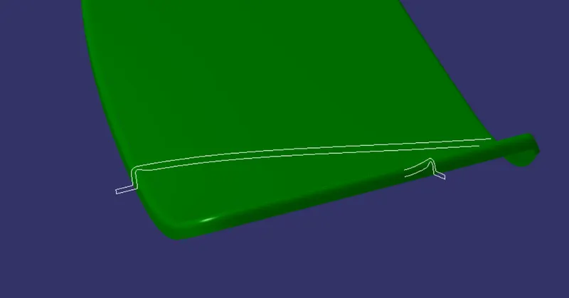
The plastic component is to be made by referring to the master structure provided as input as shown below:
The first step is to check if the given class A does not have any edges open in between the surface, for this boundary feature is used to check if the class A surface provided is good for making the plastic component.
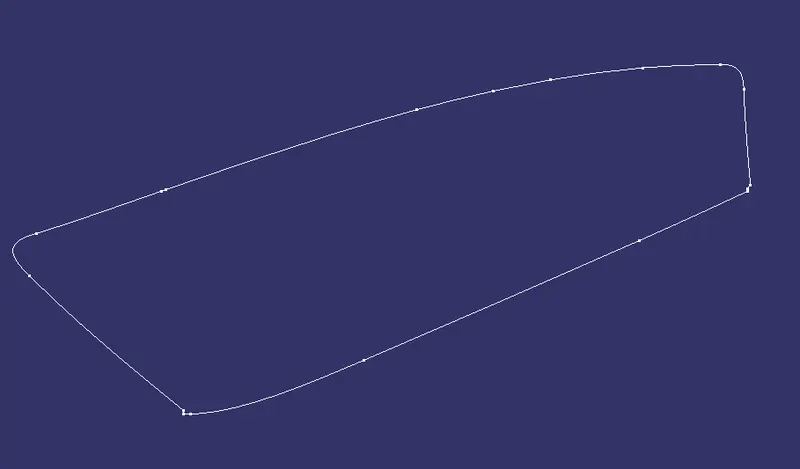
From the above image we can observe that there are no open edges in the class A surface provided, so the surface can be used to make the plastic component.
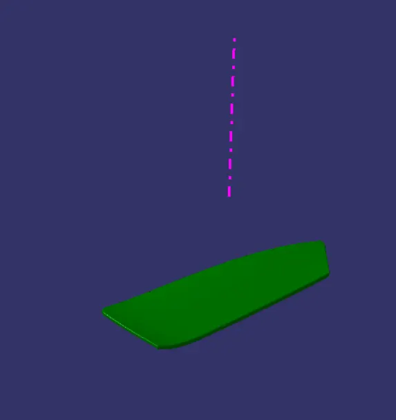
2. Determination of tooling axis
The tooling axis is the direction through which the plastic component can be tooled easily along this direction.
3. Creation of class B surface
The class B surface is present below the class A surface, on this surface various attachment features can be designed on it for the purpose of fixing the component with another adjacent component.
In this project the class B surface is created by first offsetting he class A surface by a distance of 2.9 mm by referring the master section provided as input and then creating the surfaces where the offset feature was not able to produce.
The below image shows the class B surface

4. Creation of Flanges
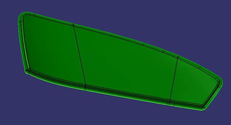
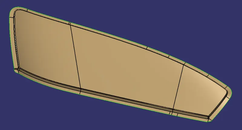
The flanges are also designed by referring to the master section by using the sweep feature, the below images shows flanges attached to the class A and class B surface's
Class A surface with flange
Class B surface with flange
5. Creation of class C surface
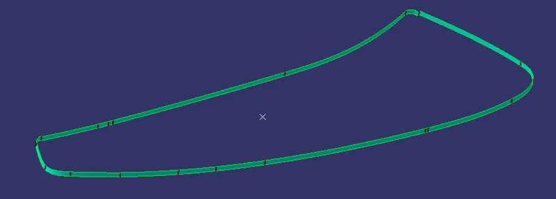
The class C surface is created along the boundary of the flange of the class A surface with the help of sweep feature. The sweep surface is created along the tooling direction feature by giving a draft of 3 degree so that the component can be easily removed after the component is moulded.
6. Closed surface creation
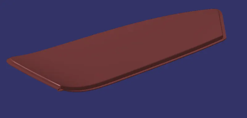
The closed surface is created by combining the class A, class B, flanges and the class C surface's, in order to check if the closed surface created is closed from everywhere, boundary feature is used, if this feature gives an error stating the surface selected is closed from all the sides then we can conclude that the surface's are closed from all the direction without any open edges.
7. Creation of closed body
The closed body of the closed surface is created with the help of close surface feature in part modelling.
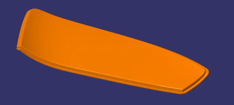
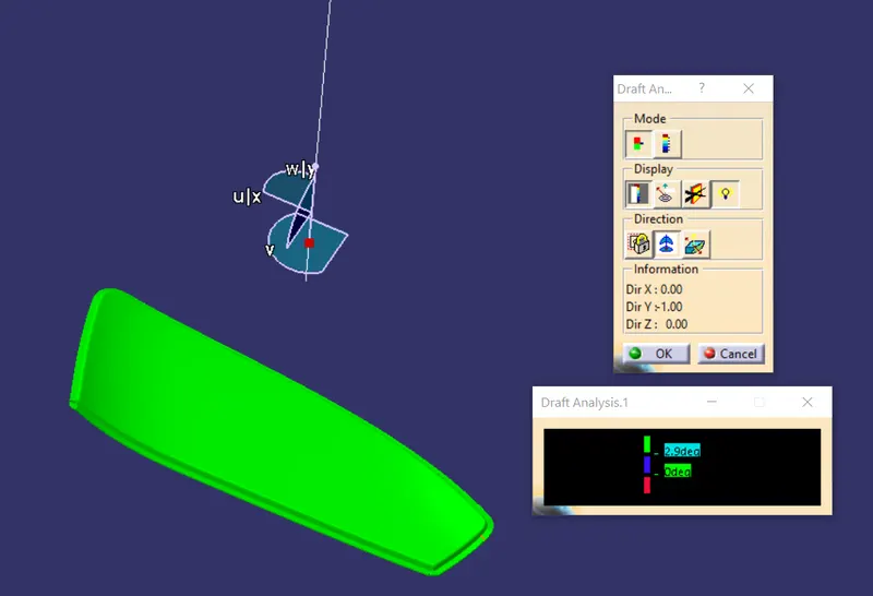
8. Draft analysis
Draft analysis is performed on the body to check if the plastic component created is clearing in all the direction and it can be tooled easily.
Final checks made to see if the component designed is as per master section or not
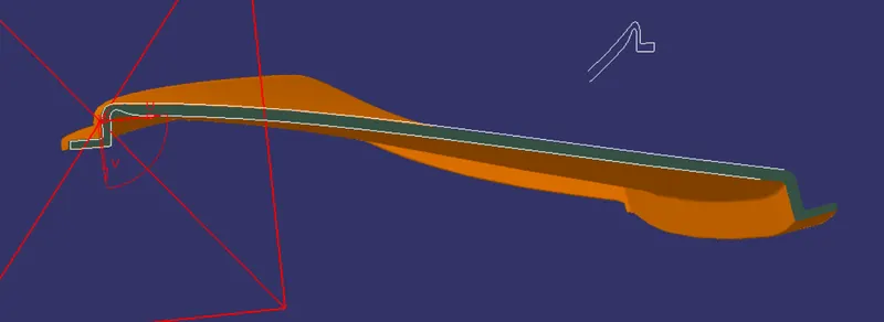
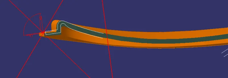
From the above images we can observe that the component created is as per the master structure.
By referring to the master structure we observed that the component thickness should be 2.9 mm and the flange's thickness should be 2mm.
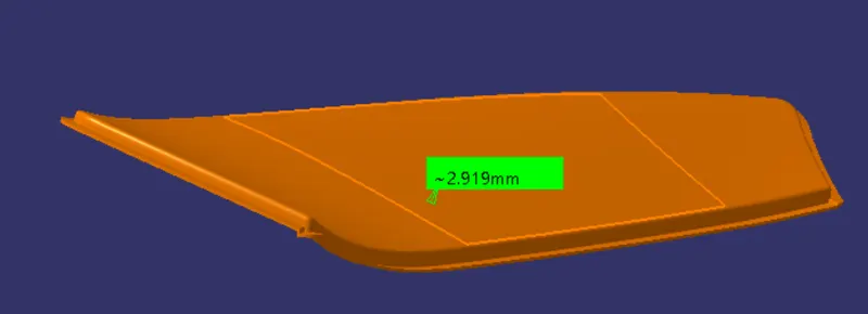
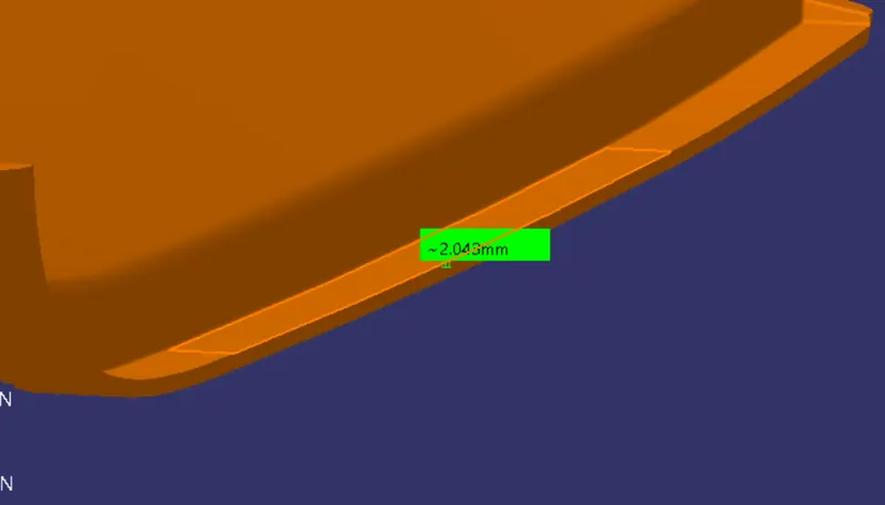
From the above images we can conclude we can observe that the thickness of the component and the flange is made accurately as per the master section.
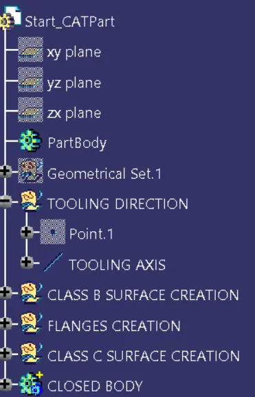
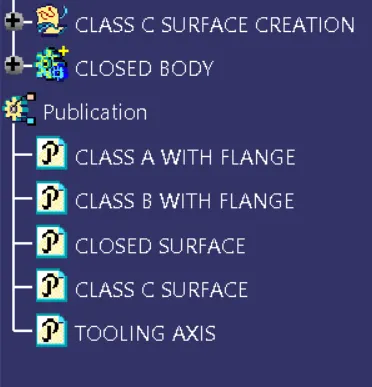
Tree Structure
CONCLUSION
The plastic component was made from the class A surface provided as input by following the master section.