Project 1
AIM: Design and Develop a PWM controlled fan load with DC motor
INTRODUCTION:
The design of the fan speed control system using Pulse Width Modulation by establishing a connection between an H bridge circuit and a Dc motor. A fan type load equation has been used to analyze the output results instead of a physical model of a fan in Simulink. The speed of the fan is varied according to the input voltage using PWM technique.
By changing or modulating the timing of these pulses the speed of the motor can be controlled. A stepwise change in the speed variation is given and the full load speed is observed. In this model, all input ports of the H-Bridge block except the PWM port are connected to ground. As a result, the H-Bridge block behaves as follows When the motor is on, the H-Bridge block connects the motor terminals to the power supply.When the motor is off, the H-Bridge block acts as a freewheeling diode to maintain the motor current.
PULSE WIDTH MODULATION:
Pulse-width modulation (PWM) is a powerful technique for controlling analog circuits with a microcontroller's digital outputs. PWM is used in many applications, ranging from communications to power control and conversion.Pulse width modulation turns a digital signal into an analog signal by changing the timing of how long it stays on and off. The term “duty cycle” is used to describe the percentage or ratio of how long it stays on compared to when it turns off.
This pulse width modulation technique is used in telecommunication for encoding purposes. The PWM helps in voltage regulation and therefore is used to control the speed of motors. The PWM technique controls the fan inside a CPU of the computer, thereby successfully dissipating the heat.
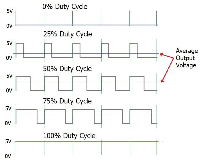
CHARACTERISTICS OF PWM FAN:
TYPES OF PULSE WIDTH MODULATION:
Pulse width modulation having different types they are,
1)Single Pulse Width Modulation.
2)Multiple Pulse Width Modulation.
3)Sinusoidal Pulse Width Modulation.
4)Modified Sinusoidal Pulse Width Modulation
1)SINGLE PULSE WIDTH MODULATION:
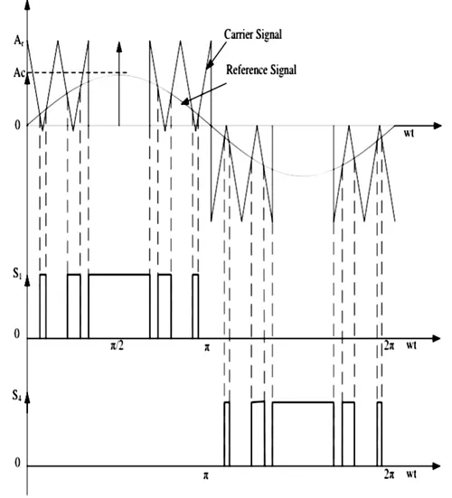
In Single-pulse width modulation, the gating signals are generated by comparing a rectangular reference signal with a triangular carrier wave thus producing only one pulse per half cycle of the output voltage
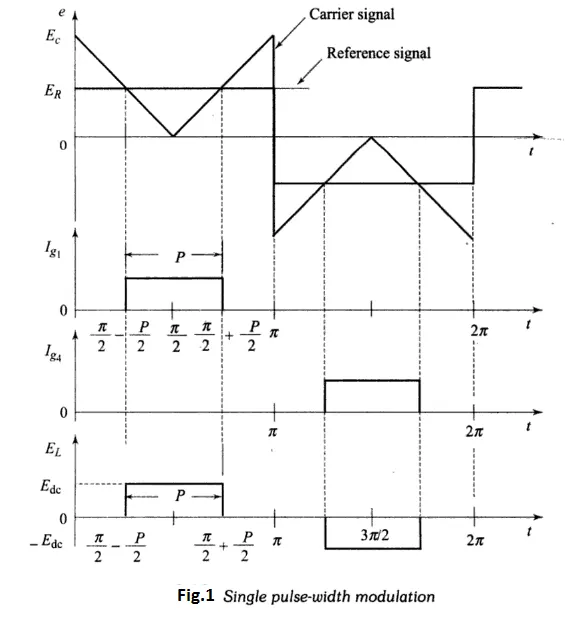
2)MULTIPLE PULSE WIDTH MODULATION:
Multiple-pulse width modulation, there are multiple number of pulses per half cycle of output voltage. The widthof each pulse is similar and can be altered by varying the carrier signal. The frequency of the triangular carrier wave is greater than that used in Single-pulse width modulation
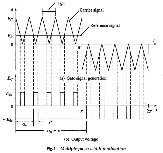
3)SINUSOIDAL PULSE WIDTH MODULATION:
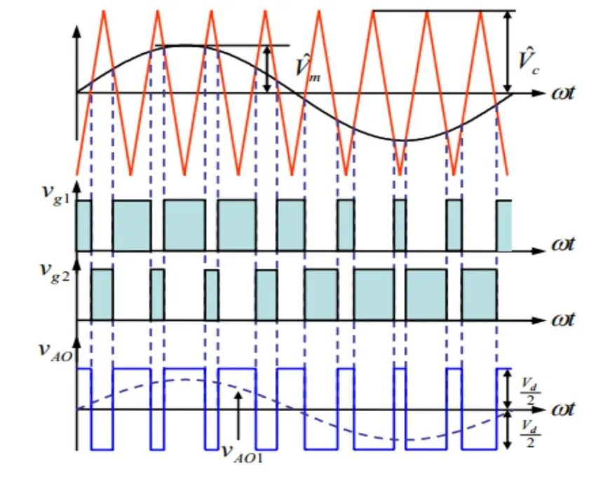
The sinusoidal PWM with third harmonic injection (THSPWM) is a type of sinusoidal pulse width modulation where a harmonic component is added to the voltage signal so that the waveform of the modulating signal has its top flattened and one reduces the period of over modulation
Sinusoidal PWM is a type of "carrier-based" pulse width modulation. Carrier based PWM uses pre-defined modulation signals to determine output voltages. In sinusoidal PWM, the modulation signal is sinusoidal, with the peak of the modulating signal always less than the peak of the carrier signal
4)MODIFIED SINUSOIDAL PULSE WIDTH MODULATION:
Modified sinusoidal PWM waveform is used for power control and optimization of the power factor. The main concept is to shift current delayed on the grid to the voltage grid by modifying the PWM converter. Consequently, there is an improvement in the efficiency of power as well as optimization in power factor
SIMULATION MODEL:
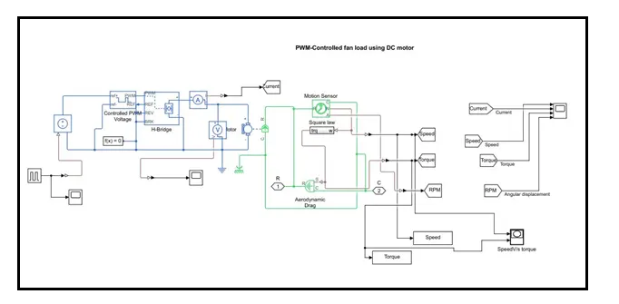
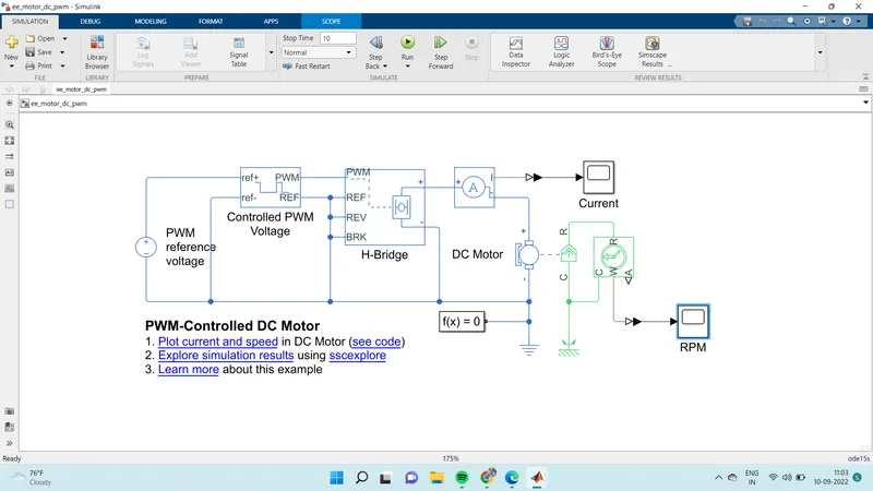
- The DC Motor block uses manufacturer datasheet parameters, which specify the motor as delivering 10W mechanical power at 2500 rpm and no-load speed as 4000 rpm when run from a 12V DC supply. H-bridge block represents a motor drive.
- The block can be driven by the Controlled PWM Voltage block in Averaged modeThis model shows how to use the Controlled PWM Voltage and H-Bridge blocks to control a motor.
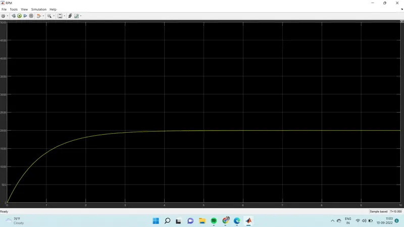
- The DC Motor block uses manufacturer datasheet parameters, which specify the motor as delivering 10W mechanical power at 2500 rpm and no-load speed as 4000 rpm when run from a 12V DC supply. Hence if the PWM reference voltage is set to its maximum value of +5V, then the motor should run at 4000 rpm.
- If it is set to +2.5V, then it should run at approximately 2000 rpm. The Simulation model parameter is set to Averaged for both the Controlled PWM Voltage and H-Bridge blocks, resulting in fast simulation. To validate the averaged behavior, change the Simulation mode parameter to PWM in both blocks
PROCEDURE TO DESIGN MODEL:
1)open the MATLAB application
2)click on the simulink option and one selection blocks popup will appear
3)select the blankmodel option in that
4)now we need to go to help center option that is shown in right above corner
5)enter the model name and select the model and open model option
6)now you will get the simulink model of PWM of dc motor
RESULTS:
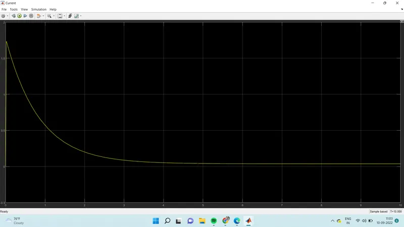
DC Motor current:
DC Motor shaft speed:
CONCLUSION:
We have succesfully Design and Develop a PWM controlled fan load with DC motor