Project 1
AIM : To Develop structural system & framing plan of a sample precast building (G+ 6) in Bhopal, India as per Indian structural codes.
1. Preparing the design basic report of the building dedsign:
Design Basic Report consists the following
- Cover page with over view
- Introduction of the building Building Description sample precast building (G+6)
- Location: Bhopal, India
- Building Dimension : 20m*8.21m
- Building Height: 24m
- Building usage : Residential purpose
- Building Construction type: Precast construction
Standards Used:
Codes used:
- IS 875 part 1: Dead loads
- IS 875 part 2: Live loads
- IS 875 part 4 : Wind loads
- IS 875 part 5: special loads and load combinations
- IS 13920 : Ductile design of Buildings
- IS 1893 : Earhquake resistant design of structures
- IS 456 :2000 Plan and reinforced concrete structures
Loads:
Dead load
Live load
Seismic load wind load
Load combinations
Structural system and stability
Calculation for element design
Calculation for connection design.
Procedure:
2. Understanding of architectural layouts of the building and structural plan is drawn accordingly:
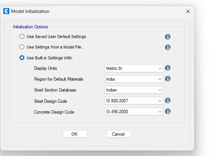
Select the Indian Design parameters
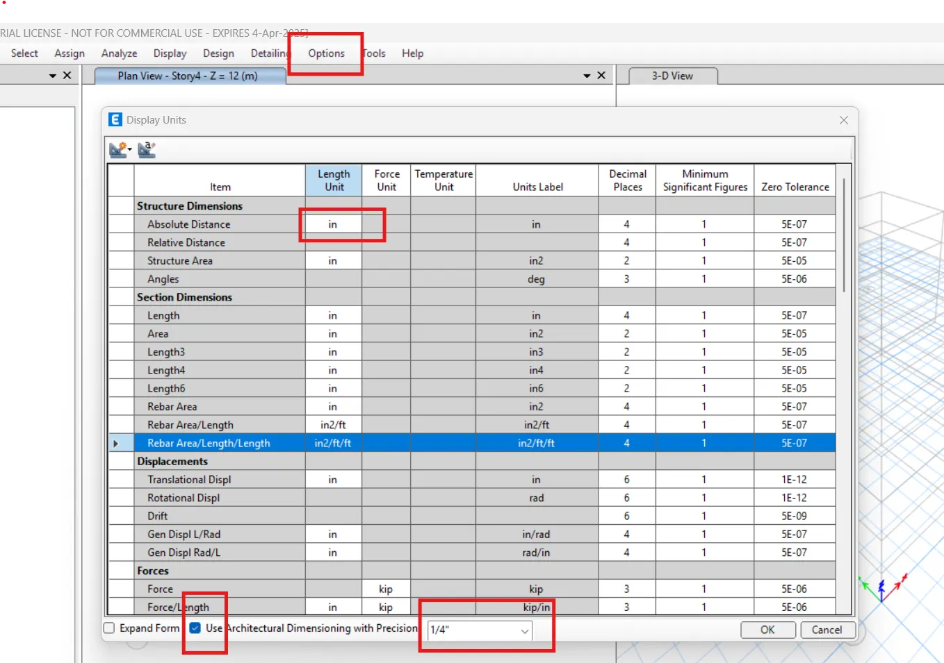
Go to options > Display units
This helps to change the units into inches as per the Architectural Drawings.
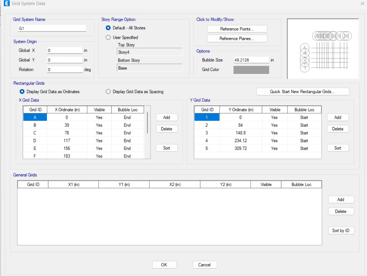
Grid system is created as per the given plan in the Auto CAD drawing
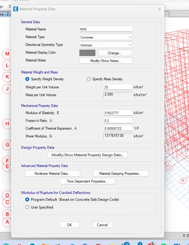
Material M40 concrete is created
Material M35 Concrete is created.
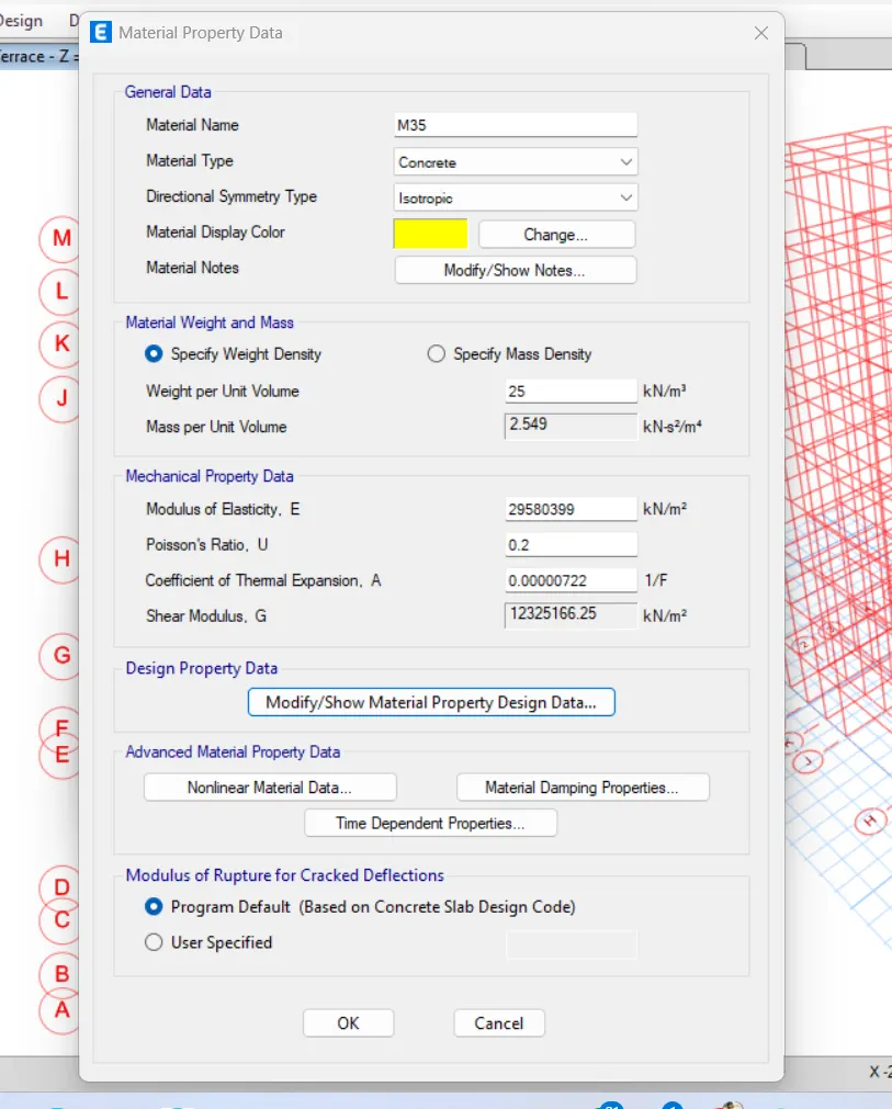
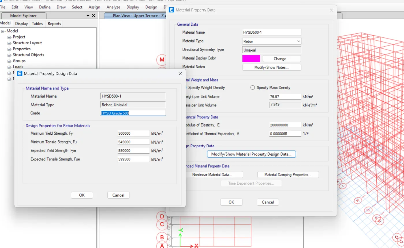
Material Fe 500 is created
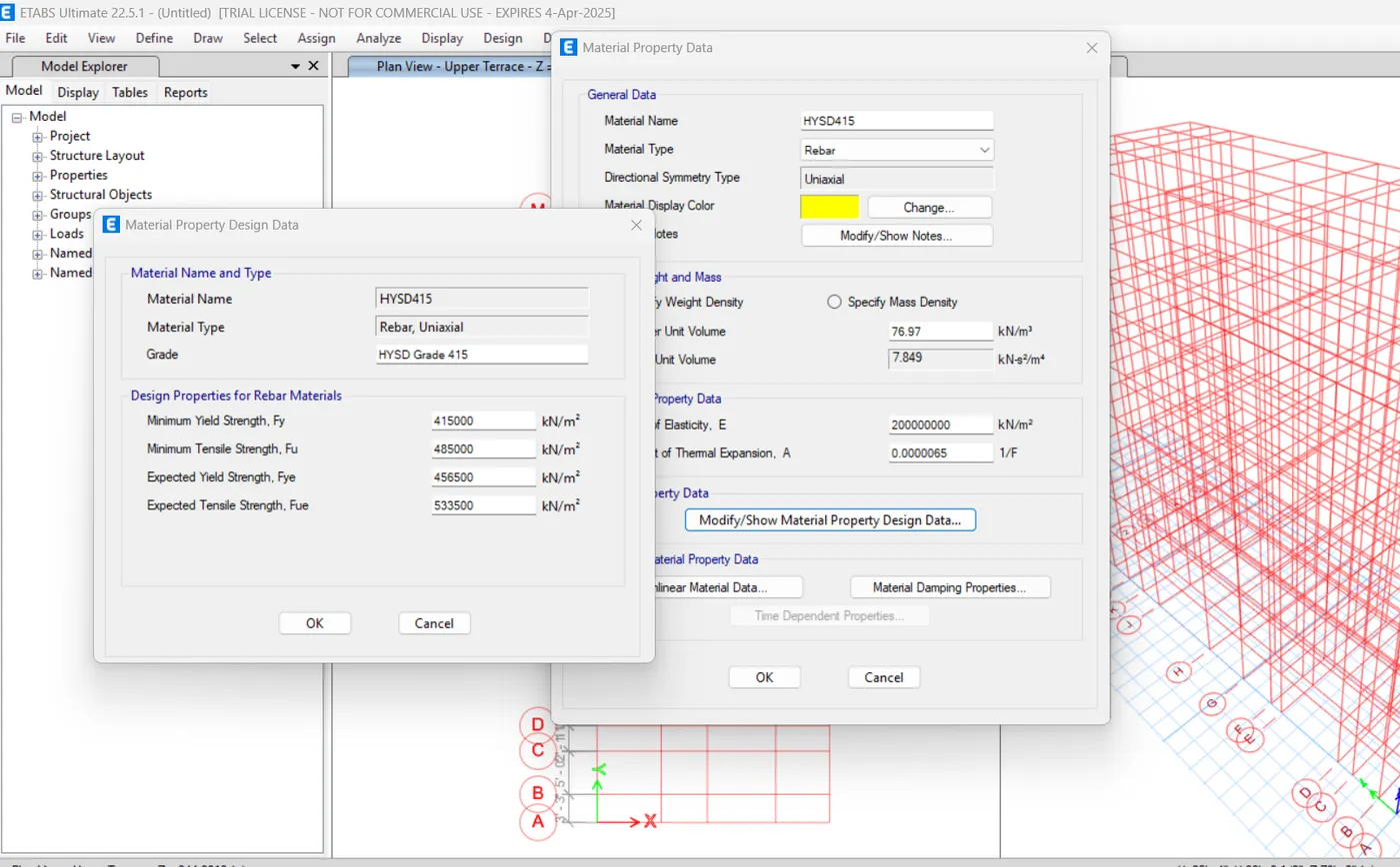
Material Fe 415 is created
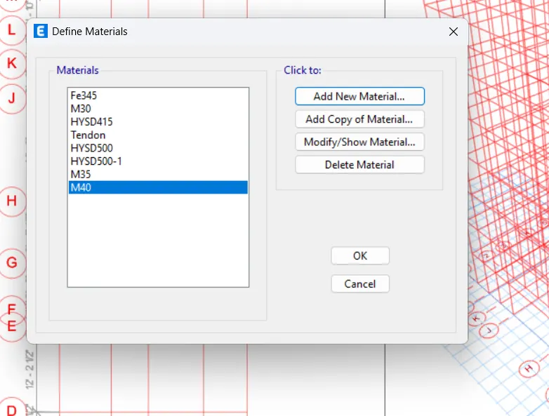
View of all materials
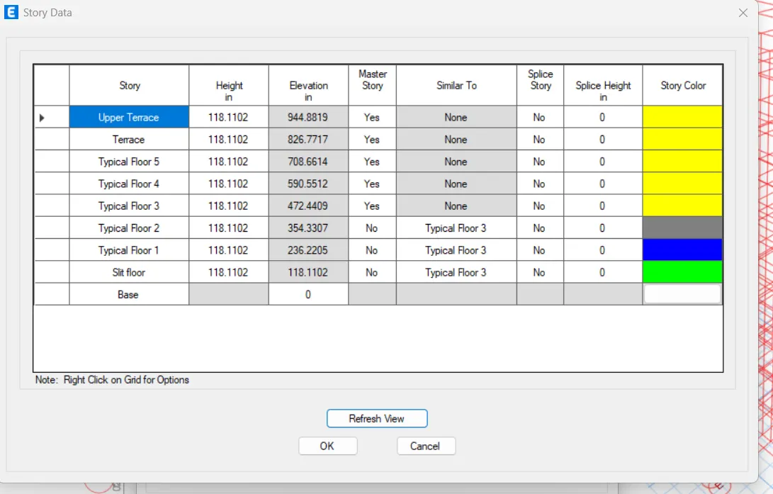
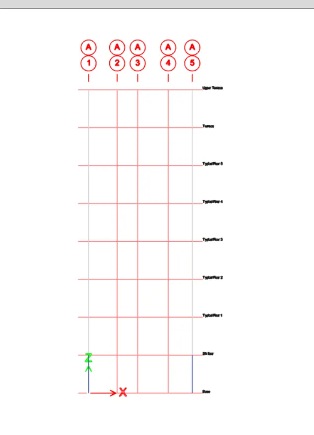
Storydata is created as per the AutoCAD Drawing
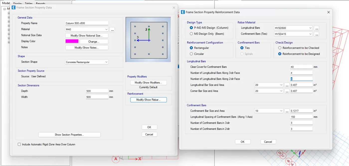
Frame Data Column 500 *500 mm is assumed with M40 Concrete Material
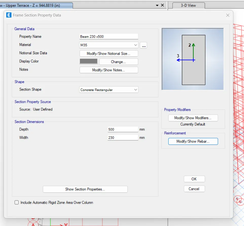
Frame Data Beam 230 * 500 mm is assumed with M35 Concrete Material
Frame Data Beam 230 * 600 mm is assumed with M35 concrete Material
Properties of column and beams are shown
Pinned connections are made for
- Column-Beam connections
- Beam slab connections
There should moment Relases for Precast for Precast Members
SLab property Data is shown here
Wall property data is created
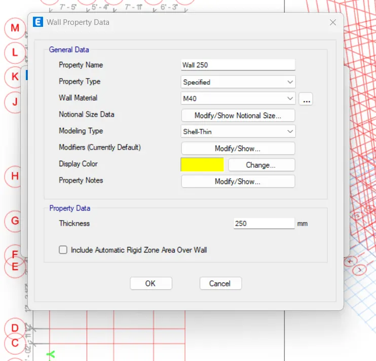
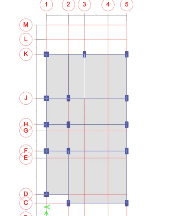
Grid view of structural plan from the Architectural plans
Replicate the floors for the other storeys
Using Edit> Replicate
3, Develop the structrual scheme (precast) for the builidg as per architectural plans
4.Preparing structural framing plans of the building along with the structural sections
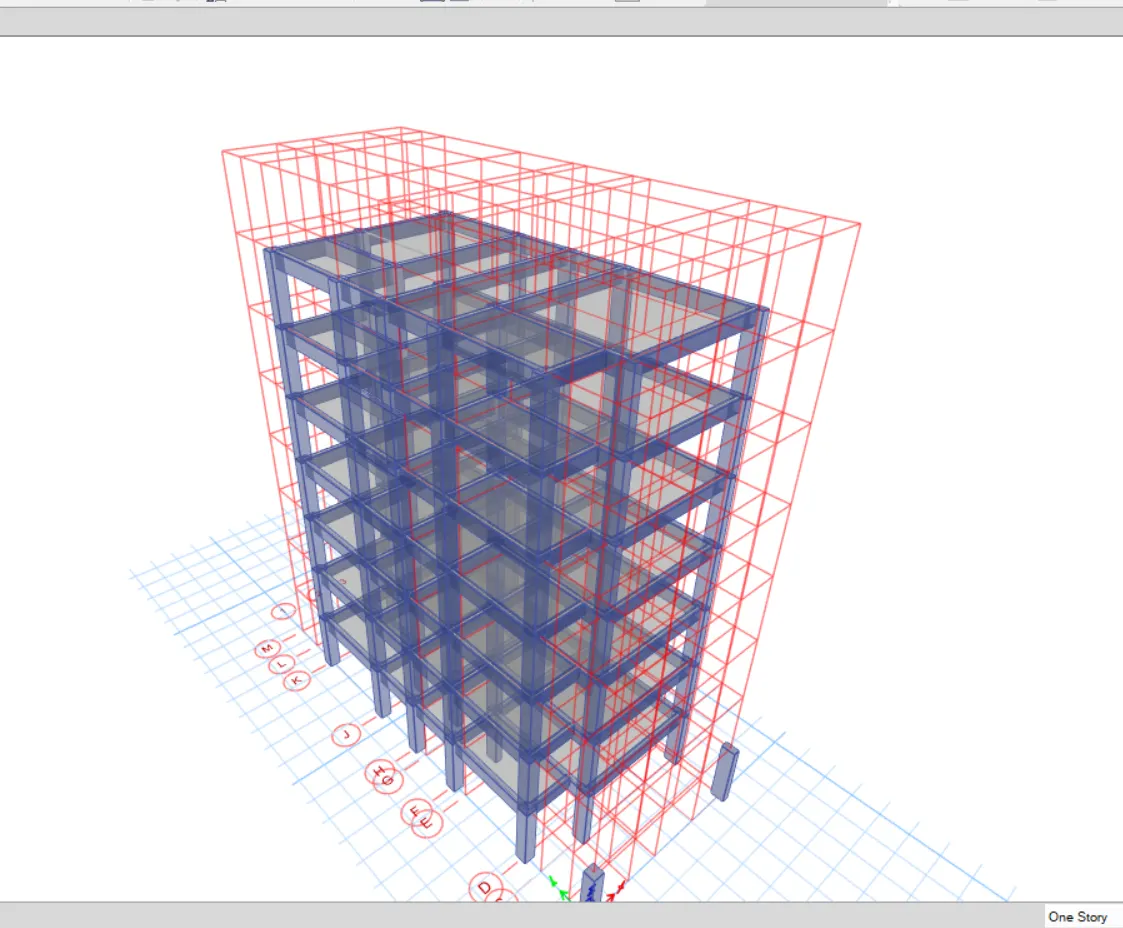
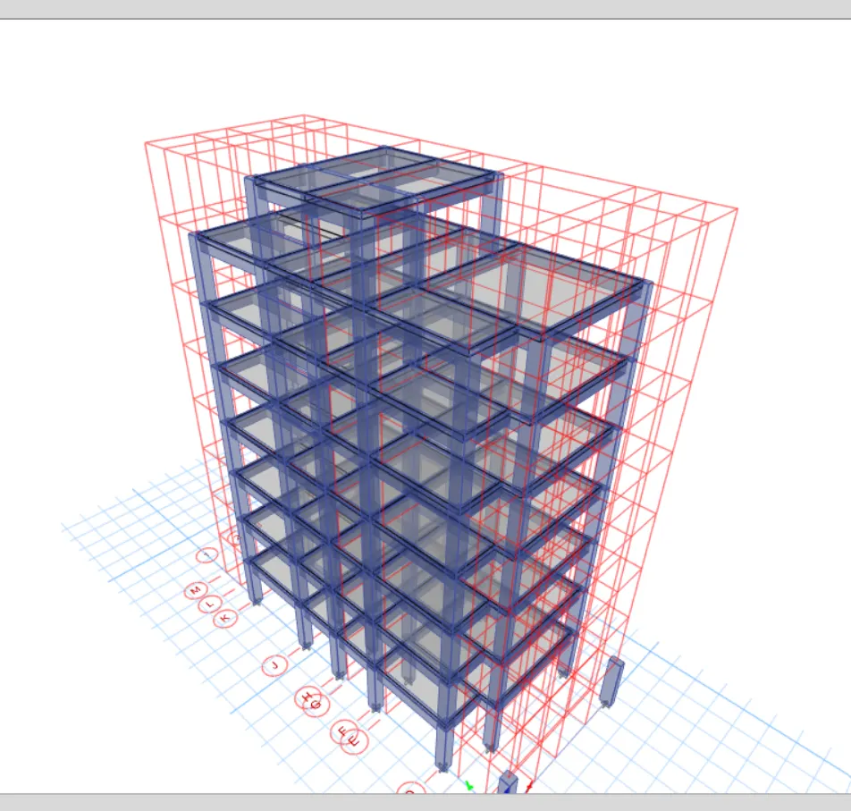
View of the structural Frame in 3D view
Elevation view.
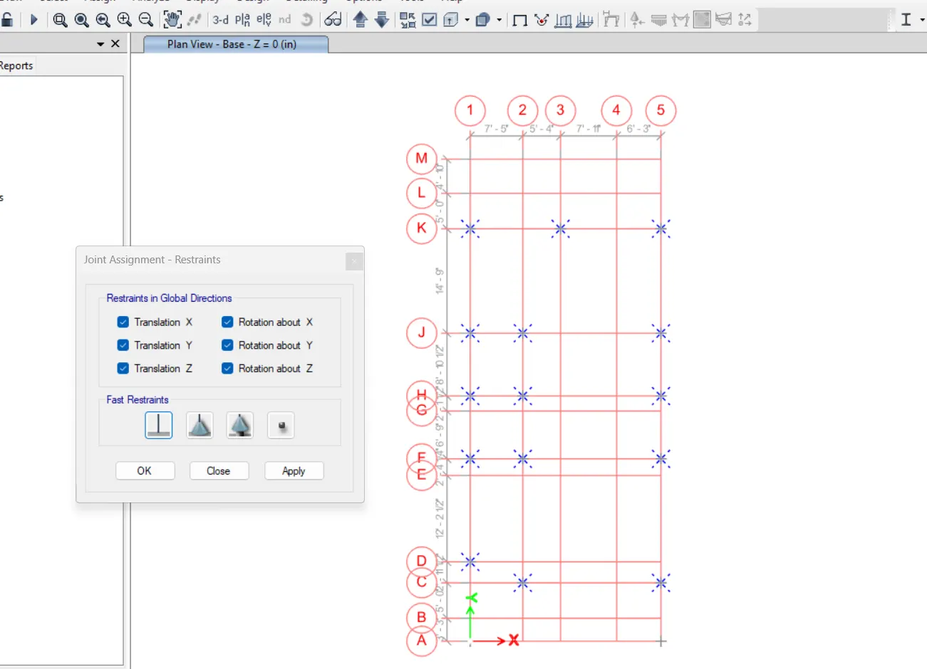
Assignement of jount Restraint
Fixed supports the Foundation
5.Create the loads path of the varipus forces to foundation
Loaad is transferred from
1. Slabs and all floors to Beams
2. Beams to columns
3. Columns to the foundation
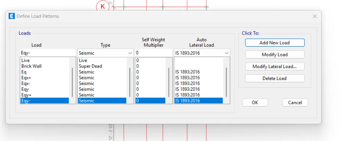
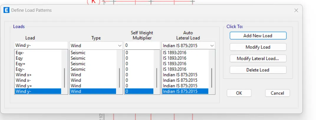
Define the loads patterns for various type of loads as shown
Seismic load patterns are added as per IS 1893-2016
Wind load Patterns are added as per IS 875-2016
6. Load Calculations for all the forces acting on the building.
7. Calculation for seimic and wind forces
As per the code Is 875 part 1 Ded load and superimposed loads are calculated.
Dead loda :
Assume uint weight of precast concrete having Reinforcement = 25KN/m ^3
Concrete doesn't have reinforcement, so unit weight of screed = 24KN/m^3
Assume Total Depth of slab D= 250mm
(Take in our calculation also )
Dead load = 0.25 *25 = 6.25KN/m^2
Super imposed Dead Loads:
Assume 230mm thick wall
Floor Height = 3.0m
Beam size = 0.23 *0.5m
Assume standard brick having density = 18KN/m^3
Now Heigth of wall = Floor Height - Beam Depth
= 3.0-0.5 =2.5m
Total superimposed Load = Height of wall *Thickness of wall * unit weigth of bricks with Plastering
=2.5 * 0.23 *18 = 10.35KN/m
IS 875 part 2
Live Loads
Living Room and Bedrooms = 3KN/m^2
Kitchen Room = 3KN/m^2
Dinning Room = 4KN/m^2
Toilet and Bath rooms = 2 KN/m^2
Corridors and passage = 3KN/m^2
Store Room = 5 KN/m^2
Balconies = 4 KN/m^2
Consider Live load = KN/m^2
Considering only for Gravity loading and no lateral loading for perliminary dimensions Load combination = 1.5DL + 1.5LL
= 1.5* (6.25+10.35) + 1.5* 5 = 32.4 KN/m^2
Design load = 32.4KN/m^2
Earthquake loads IS 1893 : 2016:
Consider Zone II as per the map in IS code 1893 for Bhopal (from fig 1 IS 1893)
Seismic Zone factor z = 0.10 table 2 of IS 1893
Consider OMRF for the given Building Based on IS 1893 for ordinary Moment Resisting Frames we have Response Reduction Factor R =3 From Table 9 IS 1893
Assume site Type = Type 2
Importance Factor of the Building l = 1 (From Table 8 IS 1893)
Moment Resistance Frames with Masonry infills caluse 7.6.2
Height of the building = 944.8819 inches = 24m
sa/g = Design Acceleration coefficient for soil types (Clause 6.4.2 (a) IS 1893) and Table 2
For use in Equivalent static method Assume medium stiff soils sa/g = 1.36/T
Clause 7.6.2 (c) Buildings with RC structural walls have Time period
T = 0.09h/d^0.5
h = height of Building = 24m
d= Based Dimension of the building at plinth level along the considered direction of the Earthquake
Considering in both directions Direction X= 323 inches =8.21m
Direction Y = 787.25 inches = 20m
Tal = 0.09* 24 /8.21 ^0.5
Ta2 = 0.483 = 0.49
Now sa/g = 1.36/T
For direction 1 sa/g= 1.36/0.76 = 1.79
For direction 2 sa/g = 1.36/0.49 = 2.78
Now For direction X
Ah = (Z/2) * (I/R) *(sa/g)
Ah =(0.10/2) *(1/3)* 1.79 = 0.023
Now For direction Y
Ah = (0.10/2) * (1/3) * 2.78 = 0.047
Base shear = vb = Ah*w
Vb = 2.3% of seismic weight for Direction X
Vb = 4.7% of sesimic weight for Direction Y
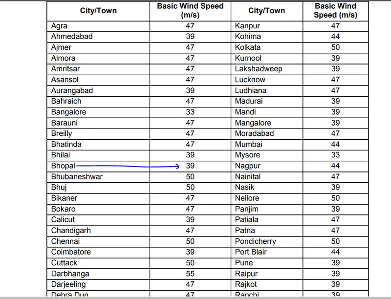
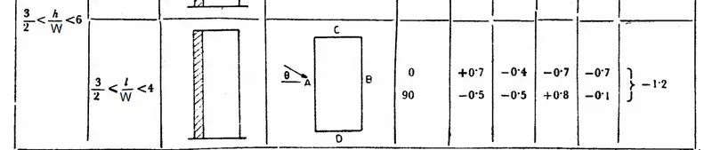
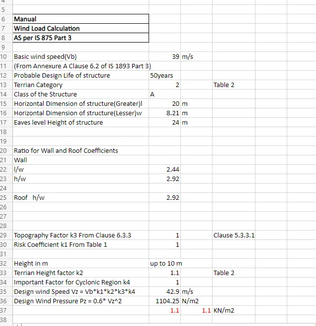
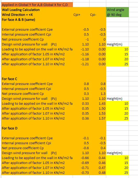
Wind load Calculation
8.identifying and dealing the irregularities of the building:
Irregularities in the Plan
In the structural grid plan it is observed that there are both verical and Horizontal, Torsional Irregularities in the plan
Vertical Irregularities:
Soft Storey at the Bottom stilr Floor is seen as per the Architectural plan. So to strength the stilt floor it necessary to provide Shear walls or strength the Columns by Capacity Design.
This helps in the reducing the Torsion of the whole building during earthquake.
Horizontal Irregularities:
The plan shows so may Open spaces in the Architecturl drawing which casuses Irregularites in the Building.
Torsional irregularities:
The combinatio of both the Horzontal and vertical Irregularties should be greater than Torsional Irregularity to find a structure to be stable.