Project 1
Project Report: Creation of Mold for a Table Fan Outer Casing (Week 7)
1. Introduction
The objective of this project is to design and create a mold for a table fan outer casing based on the given 3D model. The material chosen for molding is ABS, which has a shrinkage factor of 0.6%. The material inlet location is specified at the red dot in the given reference image. This report documents the step-by-step procedure followed to develop the mold.
2. Mold Design Considerations
- Material: ABS (Acrylonitrile Butadiene Styrene)
- Shrinkage Compensation: 0.6%
- Mold Type: Injection mold
- Parting Line: Identified based on geometry and ease of mold separation
- Draft Angle: Ensured smooth ejection
- Venting: Added to avoid trapped air
- Cooling Channels: Strategically placed to ensure uniform cooling
- Ejection Mechanism: Ejector pins considered for smooth part removal
3. Steps Followed
Step 1: Importing the Model
- The given 3D model was imported into the CAD software (SolidWorks/CATIA/NX).
- The model was analyzed for undercuts and complex geometries.
Step 2: Shrinkage Compensation
- The model dimensions were scaled up by 0.6% to compensate for material shrinkage during cooling.
Step 3: Identifying the Parting Line and Parting Surface
- The optimal parting line was determined based on the outer casing geometry.
- The parting surface was created to ensure easy separation of the core and cavity.
Step 4: Core and Cavity Design
- The core and cavity were extracted from the scaled model.
- Proper draft angles (typically 1-3 degrees) were applied to facilitate ejection.
Step 5: Gate and Runner System Design
- The material inlet was positioned at the specified red dot.
- A suitable gate type (e.g., edge gate or sub-gate) was selected for smooth material flow.
- A runner system was designed to ensure balanced filling.
Step 6: Cooling System Design
- Cooling channels were incorporated near thick sections to minimize warpage.
- A uniform cooling layout was established to improve mold efficiency.
Step 7: Venting and Ejection System
- Air vents were added at appropriate locations to prevent air traps.
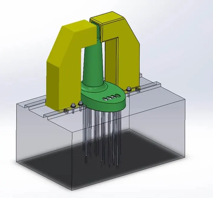
- Ejector pins were placed strategically to avoid sink marks and ensure smooth ejection.
Step 8: Mold Assembly and Analysis
- The complete mold assembly was created, including the base, guide pins, and support plates.
- Mold flow analysis was performed to check for defects like air traps, weld lines, and sink marks.
- Necessary
modifications were made based on analysis results.
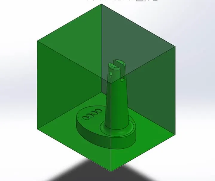
Figure – Cavity Mold Block
Design
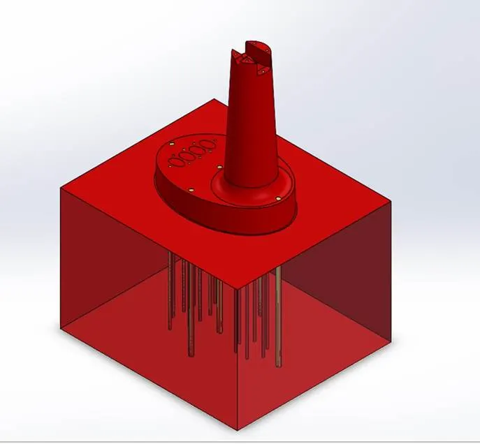 Figure –Core Mold
Block Design
Figure –Core Mold
Block Design
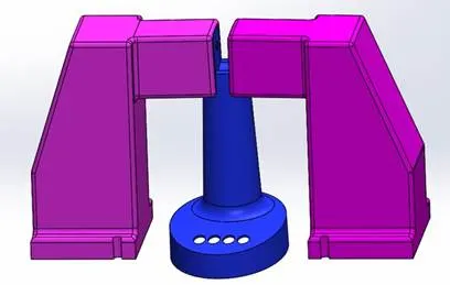
Figure – Slider of Mold Block Design
4. Challenges Faced and Solutions
|
Challenges |
Solutions Implemented |
|
Complex part geometry |
Optimized parting line and split surfaces |
|
Uniform material flow |
Designed balanced runner system |
|
Cooling efficiency |
Placed cooling channels strategically |
|
Air entrapment |
Added proper venting locations |
5. Conclusion
The mold design for the table fan outer casing was successfully completed using industry-standard procedures. By considering shrinkage, draft angles, parting lines, and mold flow analysis, an optimized mold was created. This project provided hands-on experience in mold design and validated the concepts learned in the course.