Project 1
DOOR PANEL WIRING HARNESS DESIGN
Aim:
It is to design a wiring harness for a door panel that ensures electrical functionality, ease of installation, and compliance with design standards. The harness must connect electrical components like window motors, speakers, door locks, switches, and sensors while accommodating space and movement constraints within the door.
Define a Connector
1. Open or Create the Connector Part
1. Create the Geometry:
Use the Part Design or Generative Shape Design workbench to create the connector's 3D geometry.
2. Import an Existing Connector Model:
If the connector is pre-designed, import the CAD file into CATIA.
2. Switch to the Electrical Part Design Workbench
- Go to Start > Equipment & Systems > Electrical Part Design.
3. Define the Connector
1. Access the Define Connector Tool:
In the toolbar, select Define Connector.
2. Assign Basic Properties:
Click the connector geometry to define it as an electrical connector.
Enter a name and description for identification.
4. Define Connection Points
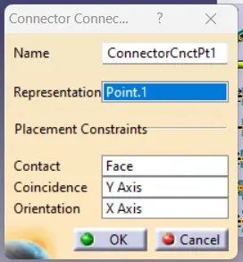
1. Add Connector Connection Points:
o Select Define Connector Connection Point from the toolbar.
o Click on the face or surface of the pin or interface where the connector will mate.
o Specify:
Direction: Set the orientation of the connection point.
Type: Define the connection type (e.g., male, female).
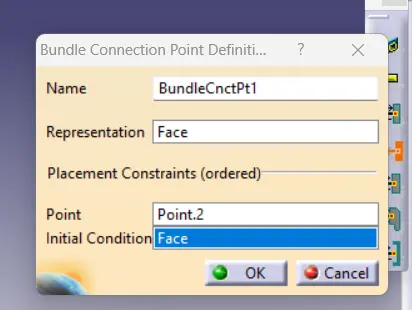
2. Define Bundle Connection Points:
Select Define Bundle Connection Point.
Click on the surface or edge where the wiring bundle enters the connector.
Set parameters such as:
Diameter: Define the maximum allowable bundle diameter.
Direction: Ensure it aligns with the intended wire routing.
5. Validate the Definition
1. Check All Defined Points:
o Ensure all connection points are correctly placed and oriented.
2. Save the Defined Connector:
o Save the part with all electrical definitions.
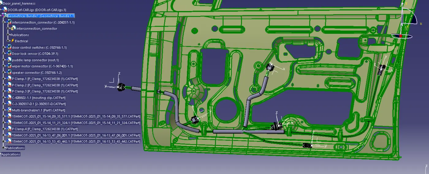
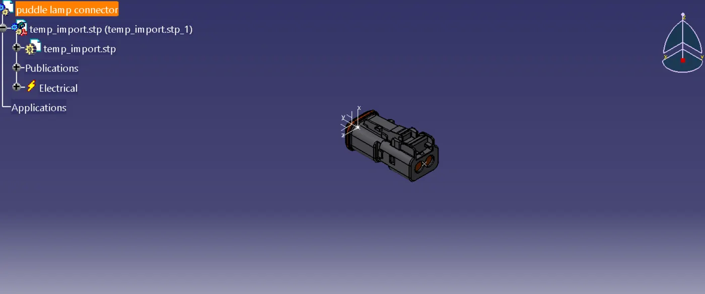
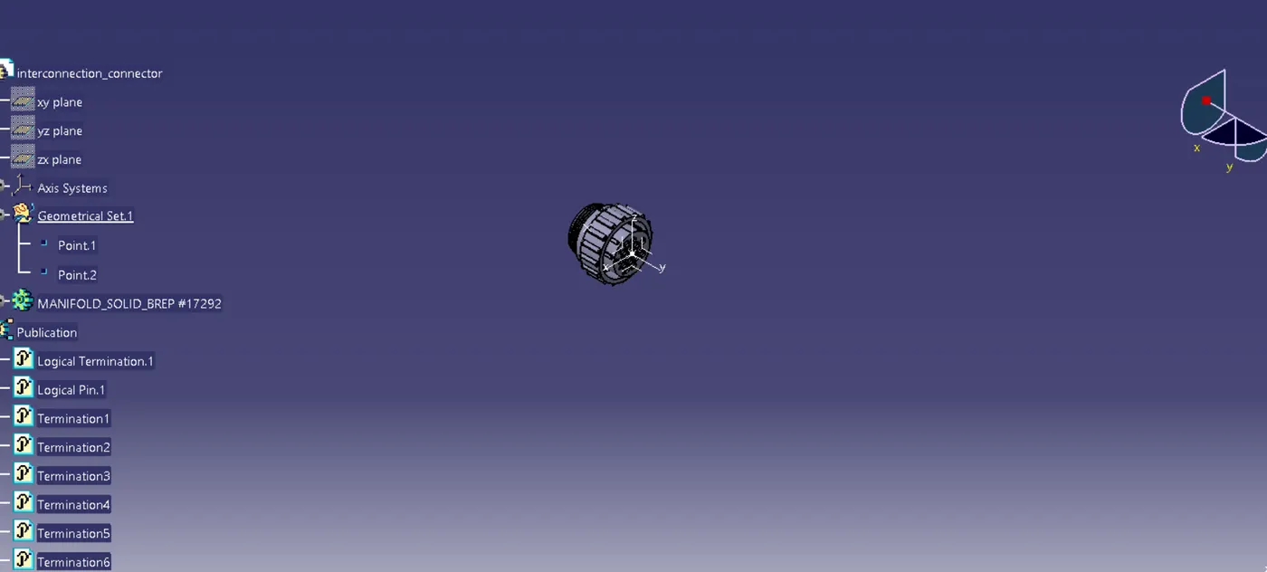
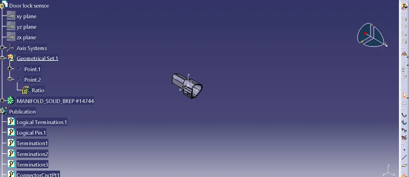
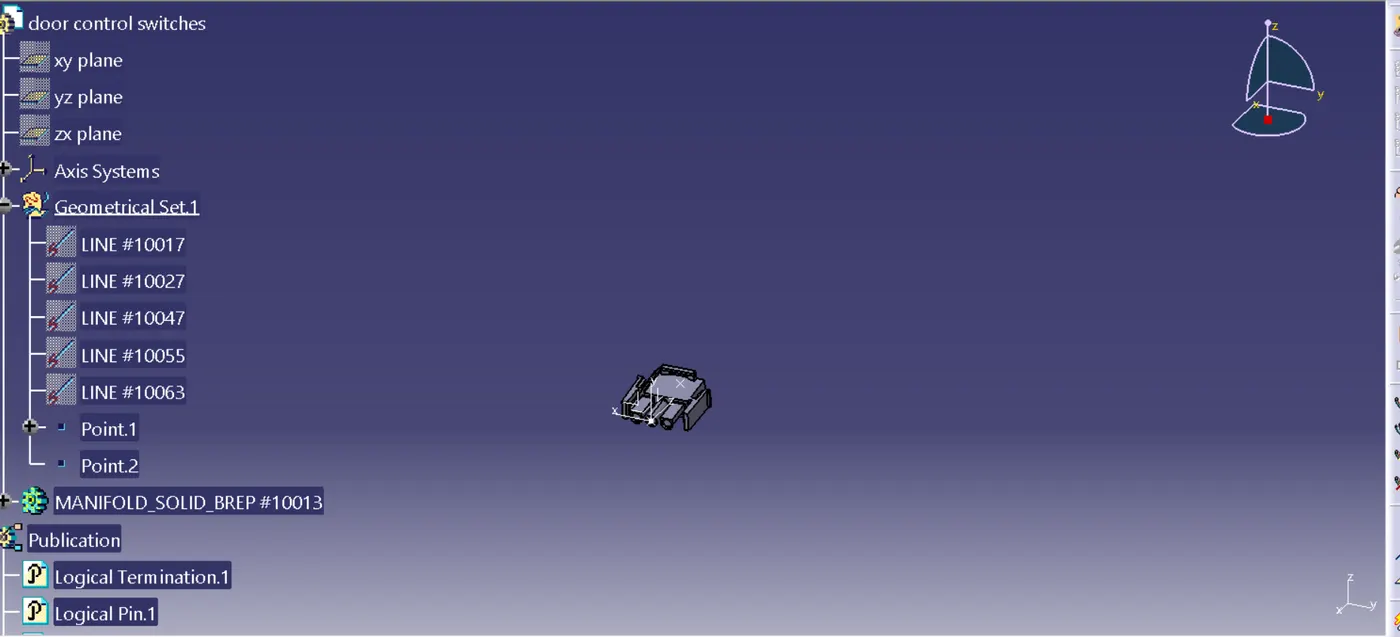
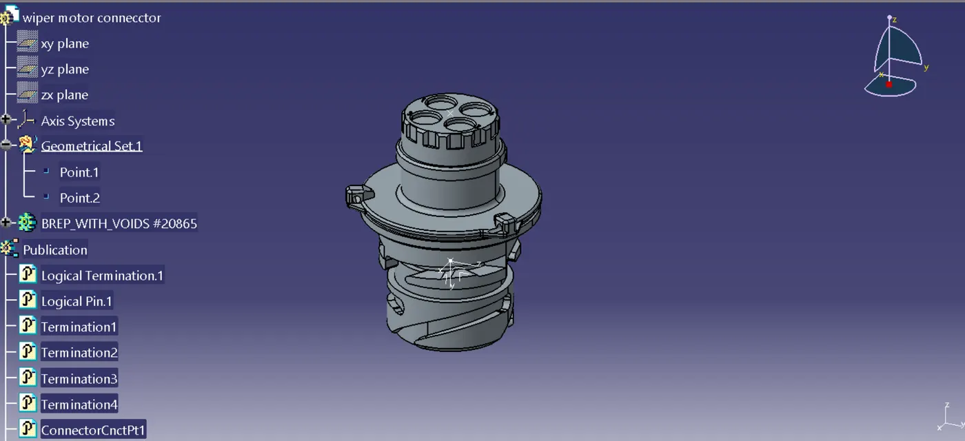
Connectors view:
CREATE A BUNDLE:
1. Prepare Your Assembly
1. Insert Components:
o Use the Electrical Harness Assembly workbench to add components like connectors, clamps, and supports into your assembly.
2. Ensure Definitions:
o Components like connectors should already have their bundle connection points defined in the Electrical Part Design workbench.
2. Switch to the Electrical Harness Installation Workbench
- Go to Start > Equipment & Systems > Electrical Harness Installation.
3. Create a Bundle Segment
1. Open the Bundle Segment Tool:
Click the Bundle Segment tool in the toolbar.
2. Define Bundle Points:
Click on the bundle connection points of the connectors or supports to define the routing path of the bundle.
3. Set Bundle Parameters:
Diameter: Define the diameter of the bundle.
Bend Radius: Ensure the radius meets design constraints to avoid sharp bends.
4. Draw the Path:
Use geometry (lines, curves, or edges) or manually define points to create the bundle's routing.
4. Add Branch Points
1. Insert Branch Points:
Use the Branch Point tool to split or merge bundle segments at specific locations.
Define additional bundle paths originating from the branch point.
2. Route Additional Segments:
Create new bundle segments from the branch point to connect other components.
5. Validate the Bundle
1. Analyze Continuity:
Use the Connectivity Analysis tool to ensure all components are properly connected by the bundle.
2. Check Bend Radius:
Verify that the bundle adheres to the specified minimum bend radius.
3. Inspect Geometry:
Ensure the bundle does not interfere with other components in the assembly.
6. Save the Assembly
- Save the harness assembly and associated bundle data for future use or modifications.
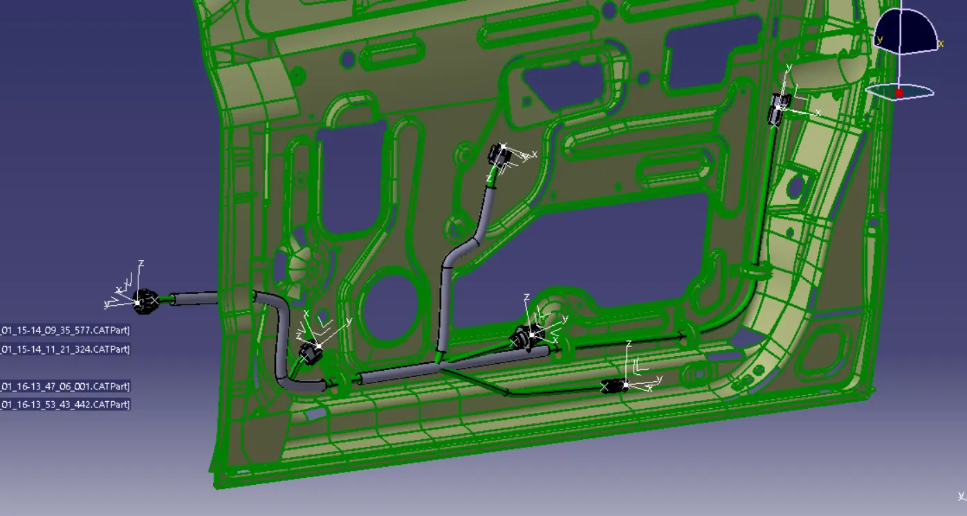
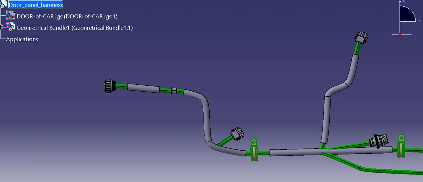
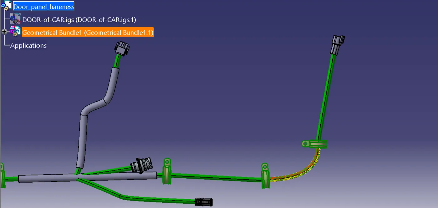
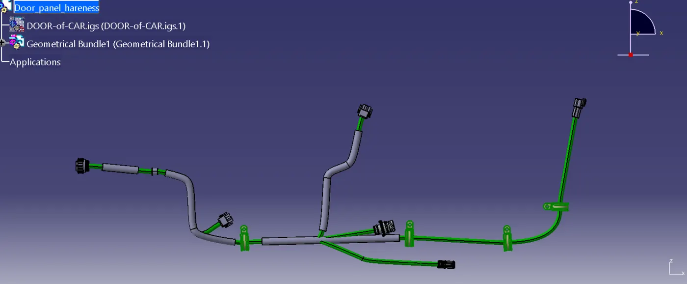
Geometric bundle views:
Flattening design:
1. Prepare the 3d harness
1. Create the harness assembly:
o Ensure the 3d harness is fully defined, including bundle segments, connectors, and branch points, in the electrical harness assembly workbench.
2. Validate the harness:
o Perform a connectivity check to ensure all components are properly connected.
3. Save the harness:
o Save the 3d harness assembly to a location accessible for flattening.
2. Switch to the electrical harness flattening workbench
- Go to start > equipment & systems > electrical harness flattening.
3. Create a flattening product
1. Insert a new product:
o Create a new product specifically for the flattening design.
2. Create a flattening file:
o Click harness flattening and name the flattening file.
o The file will be linked to the 3d harness.
4. Import the 3d harness
1. Import harness components:
o Use the extract tool to import the 3d harness components into the flattening environment.
2. Position the harness:
o Place the harness in the 2d plane using the default positioning or a custom orientation.
5. Flatten the harness
1. Use the flatten tool:
o Click the flatten tool to convert the 3d harness into a 2d representation.
o Specify parameters:
§ Support plane: select the plane on which the harness will be flattened.
§ Stretch: allow or restrict stretching of the bundles.
2. Orient components:
o Use the rotate or move tools to adjust the orientation of connectors, clamps, and other components for clarity.
6. Optimize the flattening layout
1. Straighten bundle segments:
o Use the straighten tool to clean up bundle routing and improve visual clarity.
2. Adjust lengths:
o Ensure bundle lengths match the original 3d harness.
3. Add branch points:
o If required, define or adjust branch points for proper layout.
7. Annotate and document
1. Add labels:
o Use the text tool to label connectors, bundle segments, and components.
2. Add dimensions:
o Use the dimensioning tool to specify lengths, diameters, and clearances.
3. Generate a drawing:
o Export the flattening design to the drafting workbench to create a 2d drawing for documentation.
8. Save the flattening design
- Save the flattening design and link it back to the 3d harness for updates.
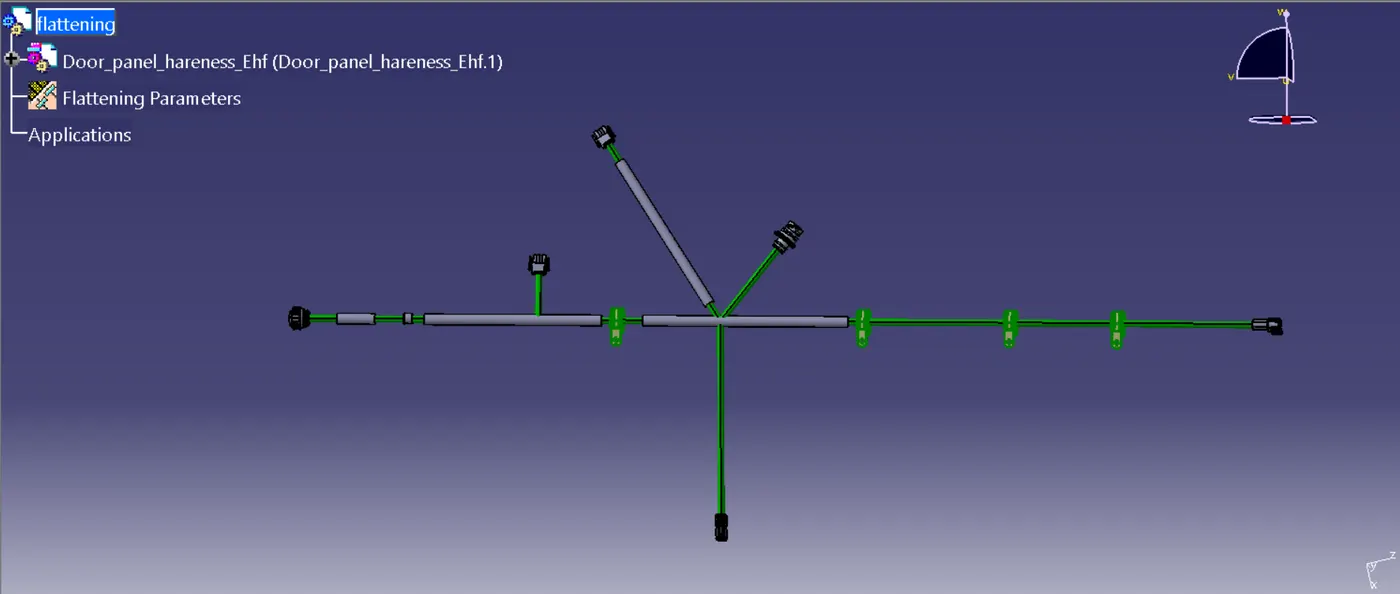
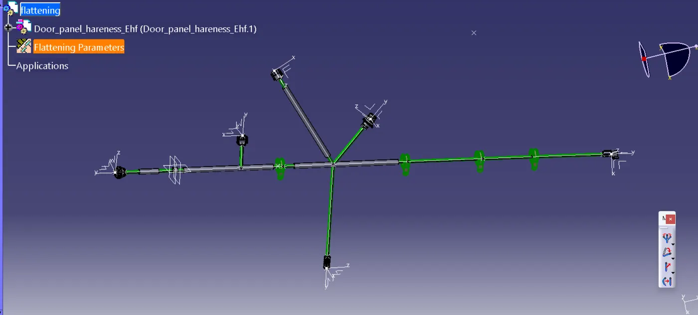
Flattening design view:
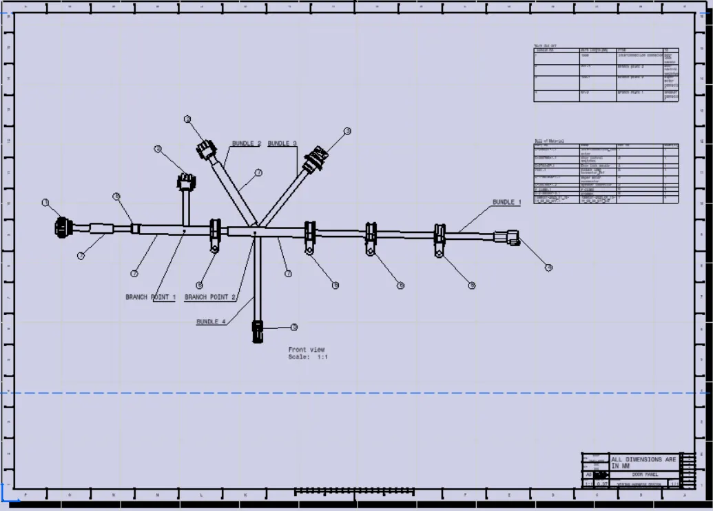
Drawing views:
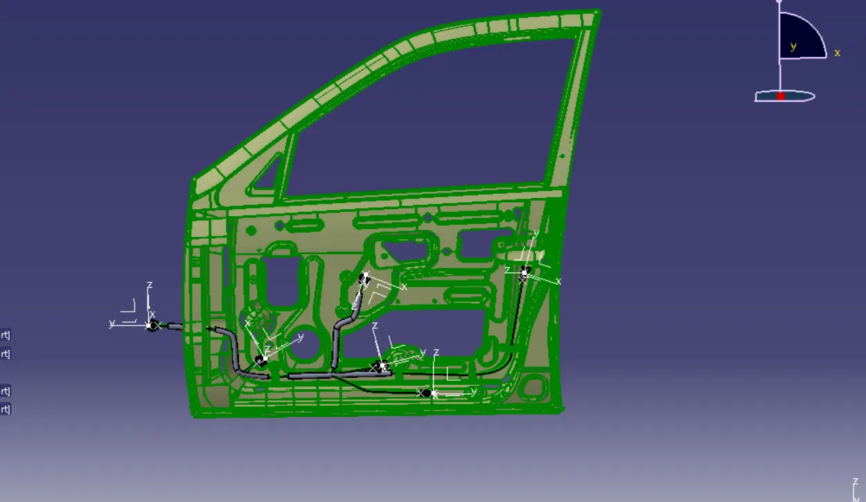
Overall views: