Project 1
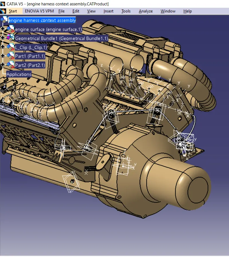
here the above image can be shows about gemoetrical bundles can be added between connector and pclamps and firtree clips
HOW I STARTED ROUTING PROCEDURE BETWEEN CONNECTORS AND CLAMPS
INTIALLY PART FILE CAN BE pasted inside the product file ,then give right click on the product tree and create new product and that product name can give as engine geometrical bundle file .
intially all the iteams can be define electrically ex like connectors ,pclamps ,firtreeclips ,bottom channel .
intially activate the product file and then change into mechanical assembly design workbench then click on the existing componet ,all components can be inserted inside the geometrical bundle tree by using snap or smart move option arrange connectors in proper way then change the workbench as electrical harness assembly design then click on geometrical bundle tree by using gemoetrical option , now the geometry is converted into electrically defined
click on multibranches option then click on route defintion select two connnector which can be electrically defined then create bundle between two connector, and for create another bundle no need to click on multilple branches , click on branch definition then create bundle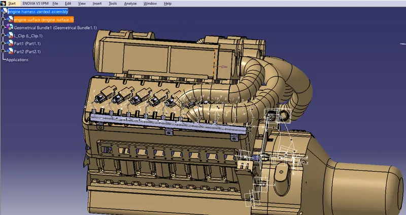
here in the above image is appear the botoom channel , it can be used for creating the multiple branches and giving connection to multiple connector .
HOW CHANNELS CAN BE ELECTRICALY DEFINED ?
activate product tree then go to mechanical part workbench and create point at two ends of channels between that channel create line , then create points in semi circular channels and go to electrical part design and select mounting equipment option and select total channel , now the channel is electrically defined , select bundle connectivity option then add faces and points in bundle connectivity where we need bundle then it can be electrically defined easily.
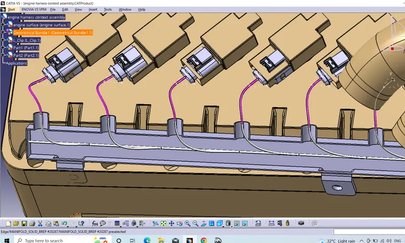
HOW TO CREATE BUNDLE INSIDE THE CHAANEL?
here we create sketch inside the channel in the partworkbench and then change partworkbench to wiring harness assembly design workbench then click on the multiple branches option then click on the external curve option and select that skectch created inside the part workbench now the bundle can be created.
HOW TO CREATE MULTIPLE BRANCH POINTS ?
double click on the bundle the add branch point option can be select and create multiple branch points where you need.
HOW TO CREATE MULTIPLE BRANCHES IN A BUNDLE ?
activate bundle and click on branch defintion then click on branch point and semi circular channel point now multiple branches be occur easily.
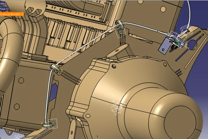
HOW TO DEFINE CONNECTOR AND P CLAMPS AND FIRTREE CLIPS AND L TYPE CLIPS ELECTRICALLY DEFINED ?
CONNECTORS : go to part workbench create point at both connector side and bundle side and create axis at connector side then go to electrical part design workbench click on define connector option and then click on the bundle connection point and then click on connector connection point and now the connector is electrically defined.
FIR TREE : click on the fir tree clip go to part design workbench then create plane at entry side and go to electrical part design workbench select the define support option and select the product.
P CLAMP : create planes at two sides both entry and exit side and then create base plane and now click on the define mounting equipment , click on the define support option and it can be converted into electrically defined