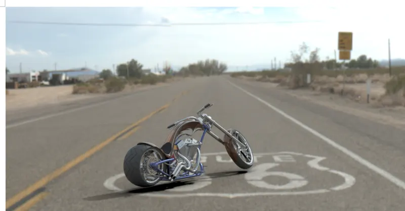
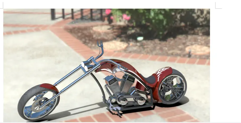
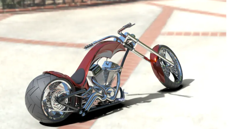
Photo Realistic Rendering
CHOPPER BIKE MODELLING AND RENDERING USING SOLIDWORKS
INTRODUCTION
This report is to show the things I’ve learnt over the past 3 weeks in Solidworks Solid modeling and rendering of a Chopper bike. I will be explaining the steps and various tools used in creating the solid model.
OBJECTIVE
- To learn more about the CAD software Solidworks
- To equip myself with the necessary knowledge in solid designing
- To model and assemble the given project (Chopper Bike) using various tools in Solidworks
- To render the complete model with its appropriate environment using Solidworks
DESIGN APPROACH
The model was divided into sperate solid bodies and later assembled. The parts designed are as follows:
- Transmission Belt
- Kick Stand
- Front fender
- Rear fender
- Chain
- Oil tank
- Pedal
- Front wheel
- Rear wheel
- Front fork
- Chassis
- Engine
- Gas tank
- Assembly of Chopper bike
- Rendering
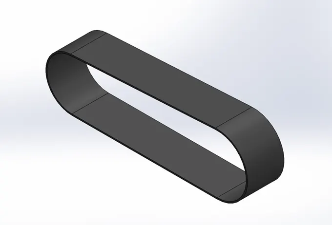
- TRANSMISSION BELT
In the process of designing the transmission belt, I came across the basic tools that require to sketch and model a part in Solidworks. The basics like commands that were in use for all the parts are:
- Sketching
The basic sketching was done using Solidworks to give the 2D appearance of the belt. Tools used were line, 3-point arc and fillet.
- Extrude Boss/Base
The extrude option was used to give the model a 3D appearance and the actual shape of the belt could be viewed
- Fillet
Once the Extrude was complete, the Belt was given fillet to the edges to give it a round finish.
An appearance of Matte Rubber was given to the transmission belt to make it look realistic during rendering.
- KICK STAND
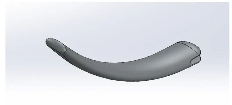
The commands used to create kick stand are:
- Sketch
The basic outline of Kick stand was drawn in a plane in 2D.
- Lofted Boss/Base
This feature allowed us to create an extrude in a curved form with different ends. This helped in creating the basic structure of the Kick stand
- Dome
The dome gave the ends of the Kick stand a rounded feature.
- Extruded Cut
This feature was used to create a cut in the required area without disturbing the main structure.
- Extruded Boss/Base
- Fillet
The Kick stand had been given an appearance of Chromium plate.
-
- FRONT FENDER
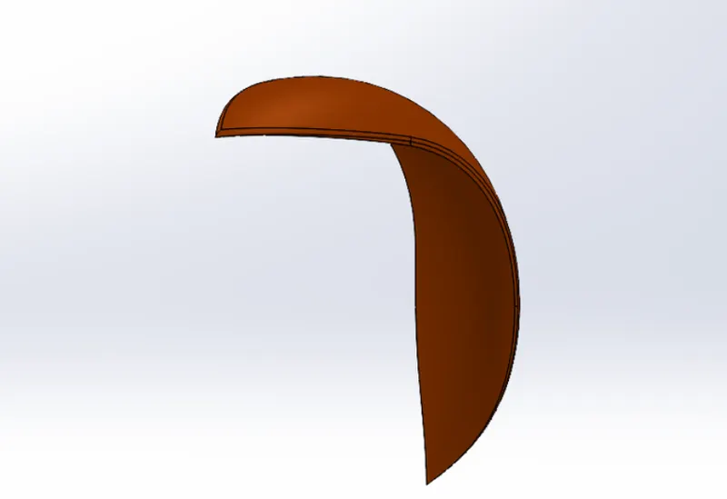
The additional features used to create this part were:
- Revolve Boss/Base
This feature allowed us to make a revolved part with the cross section of the front fender, it was then revolved around.
- Split
The split feature gave us the option to split or merge the sketch in the body.
The appearance given to the front fender was Sienna in Painted appearance.
- REAR FENDER
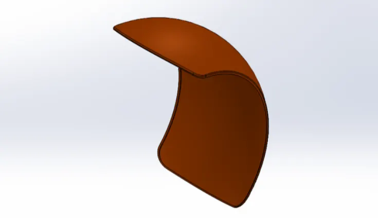
The rear fender has similar options to Front fender, but the dimensions differed from each other.
- CHAIN
The new features used to create the chain were:
- Blocks
The blocks were used to create the individual block of the chain into 2 parts and later used to create the chain.
- Pattern
The pattern command used were Circular pattern and Linear patter. The Linear pattern allowed us to copy the block of the chain into the required amount by following a linear path. The circular pattern was used to pattern the block on the arc path of the chain. Both together helped in connecting the blocks for the chain.
- Mirror
This feature allowed us to mirror the chain on the other side to complete the chain. This helped in reducing the time needed to create the chain.
The chain was given an appearance of copper.
- OIL TANK
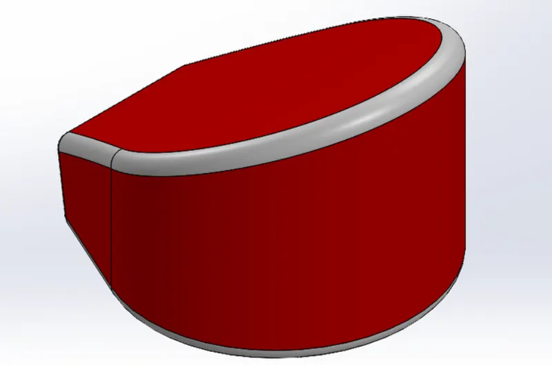
The features used to create the oil tank were:
- Combine
This feature helped in creating a new Boss Extrude with the help of 2 Boss Extrudes to give us the idea of how to get the desired shape by combining them.
- Shell
The shell feature allowed us to create a hollow interior of the part.
The other features used were fillet to give a rounded look to the whole part and appearance of Candy apple red was applied to the Gas tank.
- PEDAL
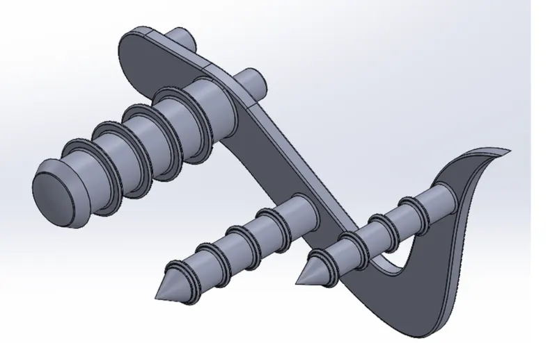
The Pedal used common features such as Extruded Boss/Base, Revolve Boss/Base, Linear Patter, Dome, Chamfer and fillet. The basic sketch was drawn and extruded as per requirement. A new feature used inside Extrude was Contour extrude where we could extrude the selected part as per our requirement. The contour was very useful when making the leg rests in of the existing Extrusion. Chromium plate was given as appearance for the Pedal.
- FRONT WHEEL
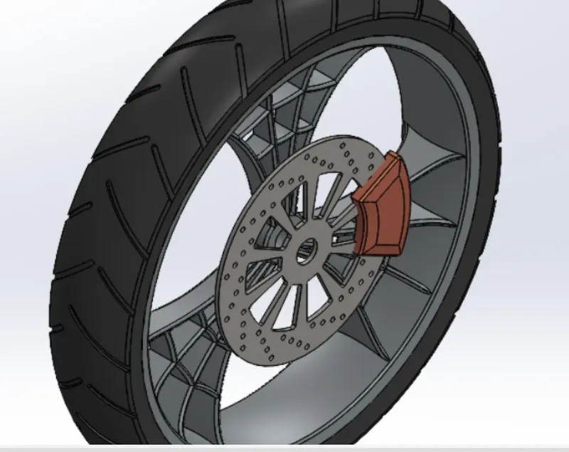
The Front Wheel is divided in 4 Solid Bodies:
- Rim
The Rim and Tire were sketched in the same Sketch and Revolved Boss/Base was used to give a circular shape from the cross-sectional sketch.
- Rotor
The Rotor was sketched after the Rim was created. The Rotor used various features such as Linear and Circular Pattern and Extruded Cut.
- Calliper
The calliper was designed to sit on top of the Rotor. The features used were Extruded Boss/Base, Extruded Cut, Fillet and Chamfer. Chromium plate was used as appearance.
- Tire
The Tire was created with the Rim from the same cross-section and was revolved using Revolved Boss/Base. The threads on the tire were sketched on a plane facing the tire surface and then Extruded Cut was used to cut on the surface of the Tire. Matte Rubber was used as appearance.
- REAR WHEEL
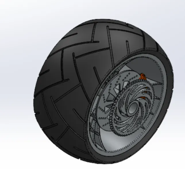
The Rear Tire process is like that of Front tire but there are a few changes in the overall dimensions. The first change was the overall width of the tire; the second change is the Extruded cut in the Rims of the Back tire to give it a nice curve. The same appearance was used.
- FRONT FORK
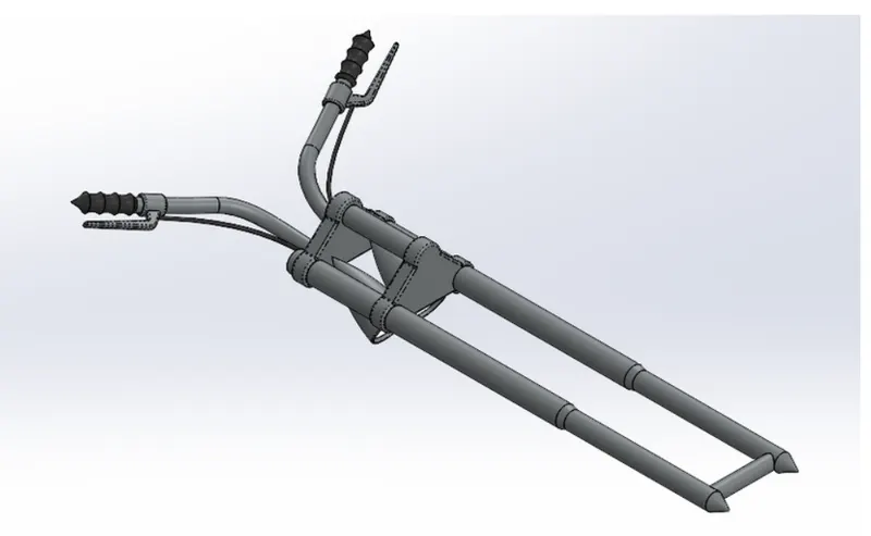
New features used in creating Front fork are:
- Move or Copy body
This Feature helped in creating the other half of the Front fork, Only one side of the Fork was created like the suspension , handle bar, brake pedal and the whole part was copied to the other side of the fork to give a full part.
- Curve Sweep
The Curve sweep helped in creating the brake wire from the handlebar to the base of the handlebar. A sketch was created using splines and made to intersect on the base. The curve sweep was done based on the sketch.
- CHASSIS
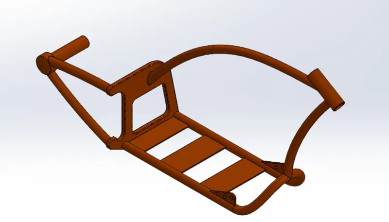
The chassis was created using a new feature called Sketch Picture where we add a new picture to the sketch and the designing is done around that. The chassis is the first part to be created using Sketch Picture in the Chopper Bike series. The main command used in creating the Chassis was the Spline feature and Project Curve. The Project Curve is used to create a curve in more than one axis using at least 2 Splines in 2 planes and then projected.
- ENGINE
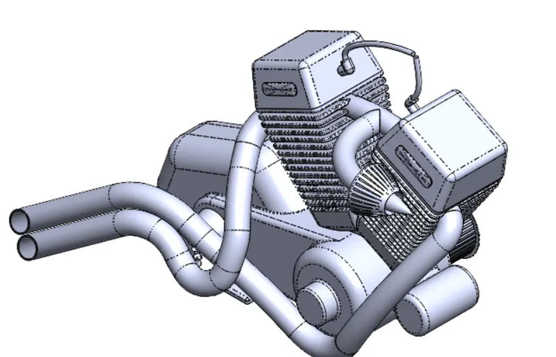
The Engine is the Second part to be modelled using Sketch Picture. The second cylinder of the engine was created using mirror where the main cylinder is created using sketch and Extrude Boss/Base and mirrored with a reference of a new plane created.
The other main part of the Engine was the exhaust coming from both the cylinders. This mainly used Splines and Project curve. Chromium plate was used as appearance.
- GAS TANK
New Features used in creating Gas tank are:
- Surface Modelling
Loft Surface, Fill Surface, Surface trim and Surface Knit are the options available to Surface model a given part. This feature is useful when creating unconventional surface bodies.
The loft surface is used to create a surface from Project curves. This is used to create the front curve of the gas tank.
- CHOPPER ASSEMBLY
- Assembly
Assembly is a process of bringing together all the parts made using different tools into one file. The assembly of the Chopper bike consists of 13 parts which were assembled in the assembly option.
- Mates
Mates is the feature where we can fix the parts in the desired location based on the assembly. There are different kinds of mates used like coincident, tangent, concentric, angle and some advanced mates such as width mates, angle mates. These mates have specific purpose and can be used according to the models requirement.
RENDERED IMAGES