Project 1
Aim: To model & design a proposed coil centre, Chennai using STAAD. Pro
Procedure:
A) For main frame and gable frame:
Open STAAD- define nodes and beams as per data> G to translation assign bay spacing.
For Area1- 30m width
roof slope=1/10=0.1
Height of roof in top level=1.5.
- Add walls>Add walls Sheeting>add roof sheeting.
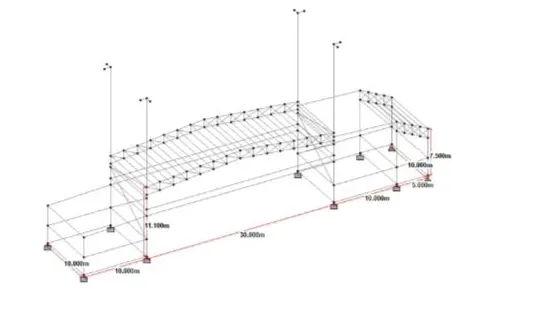
- Add propertiess>Go to preoperties section database> add and assign section to structure.
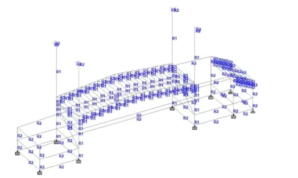
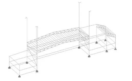
- Go to support>create support>add and assign support>fixed base and pinned base.
- Go to landing>add load definition and load case details>assign loads to the structure.
- Total DL=4.5+1.5+1.5+0.75= 8.25 KN/m
- Total LL=22.5+7.5+3.75+7.5=41.25 KN/m
- Total Coll load=0.15x30=4.5 KN/m
- Total Win Load=184 Kmph=50m/s
- Internal Pressure Coefficient=+/-0.5
- External Pressure Coefficient:
-0.9
-0.4
-0.8
-0.4
- As per given data
Design wind speed=Vb x k1 x k2 x k3 x k4
=50x1x0.94x1x1.15
=54.05 m/s
- Wind Pressure=0.6x54.05^2
= 1.75 KN/m^2
- As per IS 875 Wind direction factor Kd=1
- Area averaging factor Ka=0.83
- Combination factor Kc=0.9
Design wind pressure=1.75 x 1 x 0.83 x 0.9=1.307 KN/m^2
Wind Pressure=0.6 x 54.05^2=1.75 KN/m^2
- As per IS 875 Wind direction factor Kd=1
Area averaging factor Kc=0.9
- Combination wind pressure=1.75x1x0.83x0.9=1.307 KN/m^2
Wind load=1.307x11.1=14.50 KN/m
O+CPI=14.50+0.5-0.9=14.10 KN/m
O-CPI=14.50-0.5-0.9=13.10 KN/m
90+CPI=14.50+0.5-0.8=14 KN/m
90-CPI=14.50-0-0.8=13.2 KN/m
- Seismic Load=
EQ+X
EQ-X
EQ+Z
EQ-Z
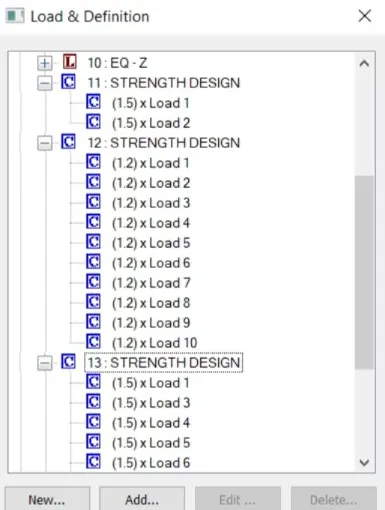
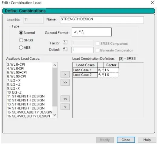
- Add load combinations> Go to load combination add as per strength and servicebility criteria.
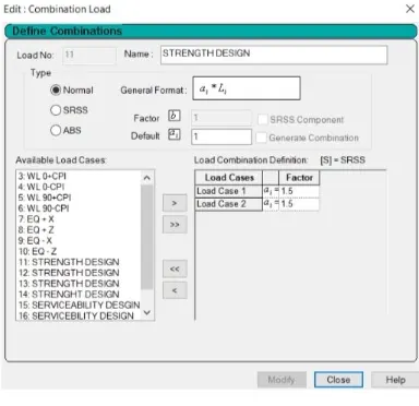
- Go to design>add design parameters>Use IS 800: 2007
- After Run analysis and check deflection and section safe results.
B) For Gable frame
Open Staad>define nodes and beams as per given data>Go to translation assign bay spacing.
For gable frame analysis and design for one frame.
- For Area1=30m width
- Roof slope=1/10=0.1
Height of roof in top level=1.5m
Add walls>Add wall sheeting>add roof sheeting
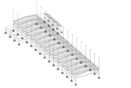
Add properties> Go to properties section database>add and assign section to structure.
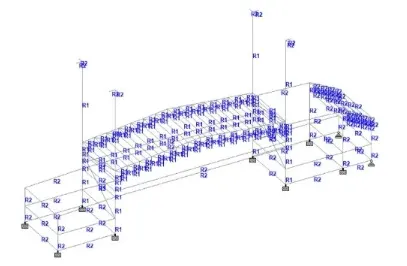
- Go to support> Create support> add and assign support>fixed base and pinned base
- Go to loading>add load definition and load case details>assign loads to structure.
- Total DL=4.5+1.5+1.5+0.75= 8.25 KN/m
- Total LL=22.5+7.5+3.75+7.5=41.25 KN/m
- Total Coll load=0.15x30=4.5 KN/m
- Total Win Load=184 Kmph=50m/s
- Internal Pressure Coefficient=+/-0.5
- External Pressure Coefficient
-0.9
-0.4
-0.8
-0.4
- Combination factor Kc=0.9
Design wind pressure=1.75x1x0.83x0.9=1.30725 KN/m
As per given data
Design wind speed=Vb x K1 x K2 x K3 x K4
=50x1x0.94x1.15
=54.05 m/s
Wind Pressure=0.6x54.05^2=1.75 KN/m^2
- As per IS 875 Wind direction factor Kd=1
- Area averaging factor Ka=0.83
- Wind load=1.307x11.1=14.50 KN/m
- O+CPI=14.50+0.5-0.9=14.10 KN/m
- 14.50+0.5-0.4=14.6 KN/m
- O-CPI=14.50-0.5-0.9=13 KN/m
- 90+CPI=14.50-0.8=14 KN/m
=14.50+0.5-0.4=14.6 KN/m
=14.50-0.5-0.4=13.6 KN/m
- Seismic Load=
EQ+X
EQ-X
EQ+Z
EQ-Z
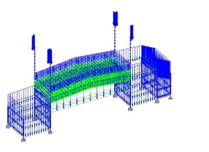
Add load combinations>Go to load combination add as per strength design and servicebility criteria.
Go to design>add design parameters>Use IS 800:2007
After run analysis and check deflection and section safe results.