BATTERY THERMAL MANAGEMENT SYSTEM (ongoing project)
1. Objective
To check the effect of Air-cooling in the Battery Thermal Management System used to cool the batteries in the Hybrid and Electric Vehicles.
2. Introduction
2.1 Lithium-ion Battery:
Lithium-ion cell performance depends on both the temperature and the operating voltage. Lithium-Ion cells work well when cells operate within limited voltage and temperature. Otherwise, the damage will occur to the cells and will be irreversible. In over-voltage situations the charging voltage exceeds the bearable cell voltage, resulting in excessive current flows and at the same time, it causes two problems. At excessive currents the Lithium-ions are deposited more rapidly than intercalation to the anode layers, Lithium ions are then deposited on the surface of the anode as metallic Lithium. This is Lithium plating. It gives rise to the reduction in the free Lithium ions and an irreversible capacity loss. (Electropaedia, 2014). There are two types of metallic lithium plating, namely homogeneous lithium plating and heterogeneous lithium plating, but the lithium plating is dendritic in form. Eventually, it can result in a shortcircuit between the electrodes.
As with over-voltage, under-voltage also brings about problems that give rise to the breakdown of the electrode materials. For the anode, the copper current collector breaks down. It causes the increase of battery discharge rate and battery voltage, however, the copper ions are precipitated as metal copper which is irreversible. The situation is dangerous for it can result in a short-circuit between anode and cathode. For the cathode, the cobalt oxide or manganese oxide will be decomposed after many cycles under low voltage. Meanwhile, oxygen will be released and the battery suffers from capacity loss.
The battery temperature should be controlled carefully. Both excess heat and lack of heat will bring about problems. Chemical reaction rates have a linear relation to temperature. The decrease of the operating temperature will reduce the reaction rate and the capacity of carrying current during charging or discharging. In other words, the battery power capacity is decreased. Moreover, the reduction of the reaction rate makes it harder to insert lithium ions into intercalation spaces. The result is the reduction of power and lithium plating causing capacity loss. High temperature increases the reaction rate with higher power output, however, it also increases the heat dissipation and generates even higher temperatures. Unless the heat is dissipated quicker than heat is generated, the temperature will be higher and finally, a thermal runaway will result.
Thermal runaway consists of several stages and each stage will give rise to more irreversible damage to cells. First, the SEI layer is dissolved to electrolyte at around 80ºC. The primary overheating may result from excessive current or high ambient temperature. After the breakdown of the SEI layer, the electrolyte begins to react with the anode. This reaction is exo-thermal which drives the temperature higher. Secondly, the higher temperature causes the organic solvents to break down with the release of hydrocarbon gases. Normally this starts at around 110 ºC. The pressure inside cells is built up by the gas and the temperature is beyond the flashpoint. However, the gas does not burn due to the lack of oxygen. A vent is needed to release the gas in order to keep cells under proper pressure and avoid a possible rupture. Then, the separator is melted and short-circuits occur between the anode and cathode at 135 ºC. Finally, the metal-oxide cathode breaks down at 200 ºC and releases oxygen which allows the electrolyte and hydrogen gas to burn. This reaction is also exo-thermal and drives temperature and pressure still further. (Electropaedia, 2014) In addition, the uneven temperature distribution is another problem of batteries. Typically, it is caused by the excessive local temperature, variable current in a cell, and the thermal conductivity of the case, as well as the placement of positive and negative terminals, and so on. (Pesaran, 2001) It results in local deterioration and even thermal runaway with reducing the battery life. (Kizilel, et al., 2009)
2.2 Operating Requirements:
The battery temperature should be controlled within temperature limits to avoid thermal issues and improve performance. The temperature range affects battery power and battery cycle life. At the same time, the temperature distribution should be even to guarantee the battery performance and lifetime. That is also the reason why the battery thermal management system is necessary for the battery system. When temperature ranges from 20°C to 40°C, battery power reaches a maximum.
The cycle life goes down slowly below 10°C because of anode plating and drops off quickly above 60°C due to the breakdown of electrode materials. Generally, the temperature must be controlled between 20°C and 40°C to ensure performance and cycle life. Moreover, the temperature distribution is controlled under 5K to keep the safety and lifetime of the battery (Pesaran, 2002). In addition, ventilation is
also essential to the battery system and should be taken into account.
2.3 Battery Thermal Management System:
The battery pack for safety, performance (both power and capacity), and lifespan reasons should be stored in a controlled surrounding where the temperature is controlled and there is no risk of thermal runaway. According
to foundational research (Pesaran, 2001), the BTMS should be equipped with four essential functions to ensure the right operation conditions of the battery pack:
i. Cooling
Due to inefficiency, battery cells will not only generate electricity but also heat. This heat should be moved from the battery pack when the battery temperature reaches the optimum temperature or even in advance. Thus, a cooling function is required in BTMS.
ii. Heating
In cold climates, battery pack temperature probably falls below the lower temperature limit. Hence, a heating function, such as a PTC heater, is required to assist the battery pack to reach the proper temperature range in a shorter time.
iii. Insulation
In extreme cold or hot weather, the temperature difference between the inside and outside of the battery pack is much larger than that in mild weather. Battery temperature will thus fall (cold) or rise (hot) sooner out of the proper temperature range. To prevent this, good insulation can slow down the falling or rise of battery temperature, especially when the vehicle is parked outdoors.
iv. Ventilation
Ventilation is required to exhaust the hazardous gases within a battery pack. In some systems, such as air systems, this function is combined with cooling and heating functions.
2.4 Air Cooling and Heating:
Air systems use air as the thermal medium. The intake air could be direct either from the atmosphere or from the cabin and could also be conditioned air after a heater or evaporator of an air conditioner. The former is called a passive air system and the latter is an active air system. Active systems can offer additional cooling or heating power. A passive system can offer hundreds of watts of cooling or heating power and active system power is limited to 1 kW. (Valeo, 2010) Because in both cases the air is supplied by a blower, they are also called forced air systems. The following figure shows a schematic description of the systems.
Forced air systems (passive and active):
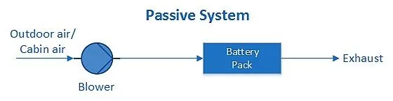
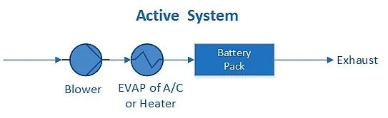
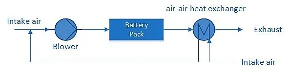
Note that the air system offers full functions of heating, cooling, and ventilation. There is no need to build an additional ventilator, but it must be noted that the exhaust air cannot be returned to the cabin again. In some cases, a heat recovery unit (air-air heat exchanger) is mounted after the battery pack in order to recover the heat from the exhaust air. It can prevent the mixture of exhaust air with intake air and at the same time provide an extra saving potential. The forced air system with heat recovery is presented below.
Forced air system with heat recovery.
3. Pre-Analysis:
3.1 Turbulent Flow:
a. Mathematical Model:
we need Reynold's number to validate the turbulent flow
`Re = (rho*V*D)/mu`
Where:
`rho` = Density
`V` = Velocity of Fluid
`D_h` = Hydraulic Diameter
`mu` = viscosity of the fluid
In our case we have air as a medium hence,
`rho = 1.225 ((kg)/m^3)`
`V= 4(m/s)`
`mu = 1.7894e-05 ((kg*m)/s)`
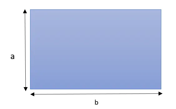
`D_h` for the rectangular duct is given as `(2*a*b)/(a+b)`
Here we have a = 78mm and b = 38mm
Therefore Hydraulic Diameter is 51.103 mm = 0.051 m
Therefore `Re = ((1.225)*(4)*(0.051103))/(1.7894e-05) = 13993.78`
because Reynold's number is greater than 4000 we can conclude that the full turbulent flow is varified.
b. Eddiy-Viscosity Turbulent Model (i.e `k- epsilon` turbulence model)
In our case, we will use the `k- epsilon` turbulence model to compute Reynold's number, because it is a kind of eddy viscosity turbulent model. it is not a conservation law. it is based on guesswork. the eddy viscosity can vary spatially, it has to be computed as a part of the solution process.
the molecular viscosity comes from an exchange of momentum between adjacent layers due to molecular motion. i.e we are getting turbulent shear due to momentum exchange.
In the `k- epsilon` turbulence model, the k represents the turbulent kinetic energy (i.e it is a measure of how much energy is contained in the fluctuation). hence larger the turbulent fluctuation the larger is k.
the epsilon represents the Turbulent dissipation (i.e it is a measure of the rate at which turbulent kinetic energy is dissipated.
The Eddy viscosity can be calculated following fashion
`mu_t/rho approx (C_mu * k^2)/epsilon`
i.e K increases Eddy viscosity increases
also epsilon increases then Eddy viscosity decreases.
Overall Influent, we need to look at the following conservation equation such as
1. Conservation of mass i.e continuity equation.
2. Conservation of Momentum in x and y direction i.e Navier-Strokes Equation.
3. Conservation of K.
4. conservation of Epsilon.
When we apply the governing equation, we are considering an infinitesimal fluid particle moving within the flow and we get a partial differential Equation. when we apply the governing equation to a control volume then we get the integral form of the governing equation. in CFD we apply the governing equation approximately in software and which convert the governing equation to a large set of algebraic equation (Numerical Methods) i.e it goes from calculus to linear algebra. the large set of an algebraic equation inverted in the computer while solving.
The basic idea in FVM is we take a flow domain and divide it into little chunks (or) control volume and apply conservation to each little chunk.
3.2. Governing Equations:
In general, We want to find out the velocity, pressure distribution, and Wall friction within the channel after that we can get the power needed to pump the flow-through channel.
a. Conservation of Mass (continuity Equation):
According to the conservation of mass volume of fluid-particle within control, the volume cannot change. from the continuity equation, we get the following equation.
i. Differential form:
`grad*vec V = 0`
ii. Integral form:
`int_s vecV*hatx*ds = 0`
b. Conservation of Momentum:
from `F=ma`
i. Differential form:
`rho(grad*vec V)*vec V = - gradP + mu*grad^2 *vec V`
Where:
`rho` = Density
`grad*vec V` = Acceleration
`vec V` = Velocity
`- gradP` = Net Pressure force
`mu*grad^2 *vec V` = Net viscous shear
ii. Integral form:
`int_s rho*vecV(vecV*hat n)*ds = - int_s P*hat n*ds + vec F_v`
From all the above equations we have three unknown equations and three unknown functions one from conservation of mass and two from conservation of momentum. i.e two velocity components in both x and y direction u(x,y); v(x,y), and one pressure component p(x,y).
Unknowns: u(x,y) ; v(x,y) ; p(x,y)
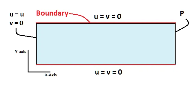
Note: There is no exact solution is present except the region downstream where the flow is fully developed.
3.3. Boundary Conditions:
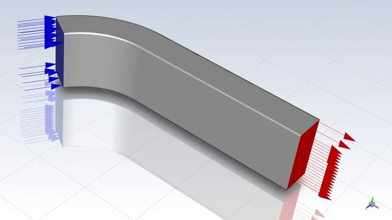
Inlet Velocity: 4m/s
Outlet: Pressure
volumetric Heat Source: Battery
Material Property: Aluminium (correct it)
The number of cells: 5
3.4. Hand Calculation:
We need to calculate the power density as a Volumetric heat source for each cell. the calculation is shown below.
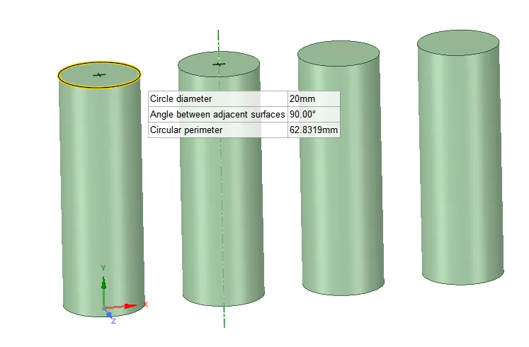
Formulas:
The volume of Each Cell = `(pi/4)*L*D^2`
Power = Energy/Time
Power Density = Power/Volume
Calculation:
Diameter : 0.02 m
Length : 0.059 m
Energy: 6015.850 J
The volume of Each Cell = (pi/4)*L*D^2 hence Volume= 1.85673E-05 m^3
Time: 3*3600 = 10800 sec
Power: 0.557019
Power Density: 30000 W/m^3
4. Procedure
Define the Analysis system in Ansys Workbench as a fluid flow (fluent).
4.1. Geometry:
Import Geometry in SpaceClaim and suppress the outer casing.
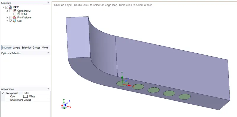
4.2. Meshing:
Set Preference as CFD in the details of mesh and Element size as 5mm. In meshing, we mesh the geometry by Defining the sizes of the different elements. Where the fluid volume and cells mesh differently as shown below due to the type of system.
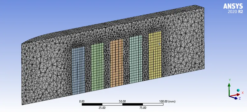
we are defining the name of the inlet and exit of the boundary and also naming each cell and fluid volume.
4.3. Model setup:
In Ansys fluent we are taken, density-based solver due to lower velocity. after that defining the volumetric heat source parameter for each cell as a 30000 W/m^3. Also defining the inlet velocity parameter at the inlet boundary as a 4 m/s. using a k-epsilon method as a viscous model and standard method.
Physical Model:
Time: Steady
Type: Density-based (due to low Mach Number)
Energy (on)
Turbulent Model: K-Epsilon
Defining Plot as a volumetric average temperature and Number of iteration as 500.
5. Results
5.1. Pressure Result:
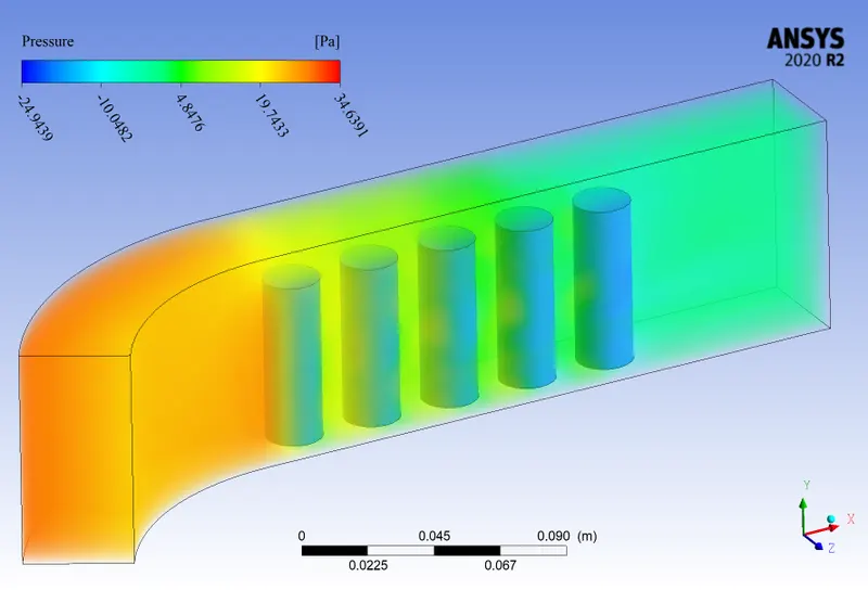
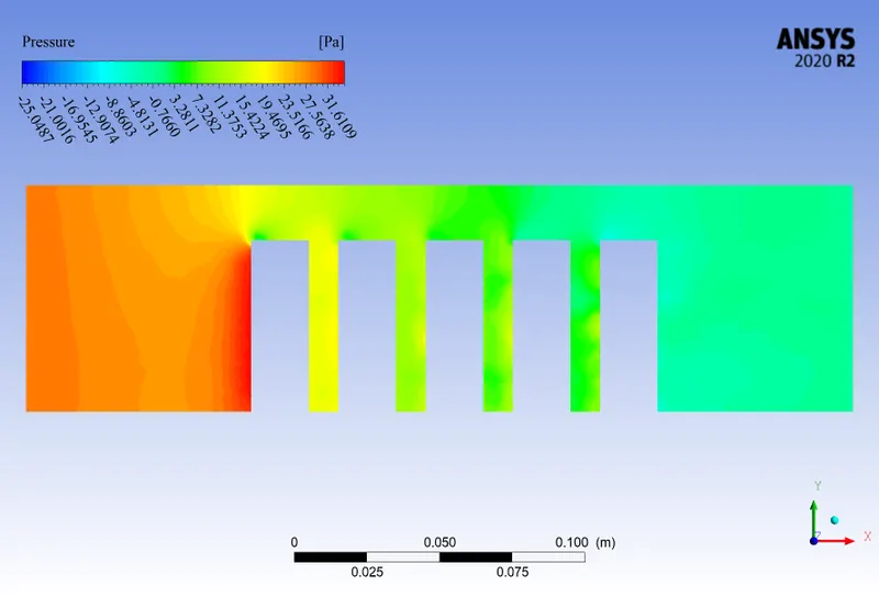
The Pressure is higher at the inlet due to higher drag between air and cell as aspected.
5.2. Velocity Result:
Here we can see that velocity is 4 m/s at the inlet which is the default, but the velocity is increases at the top and the sideways of cells. this is due to the decrease in area, and as we know that as the area decreases velocity increases. the rate of heat transfer is increased also.
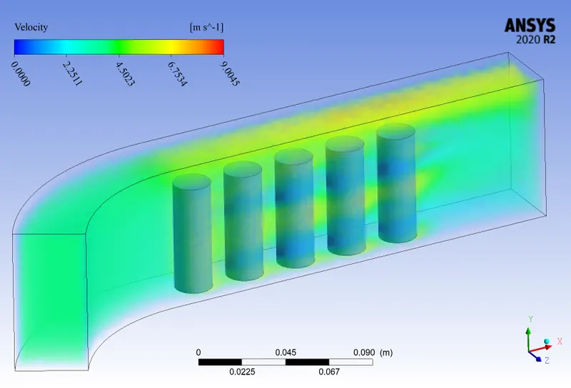
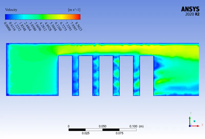
As we discussed in a pre-analysis we have three unknown equations and three unknown functions one from conservation of mass and two from conservation of momentum. i.e two velocity components in both x and y direction u(x,y); v(x,y), and one pressure component p(x,y). The Velocity at the wall is zero due to wall share.
5.3. Temperature Result:
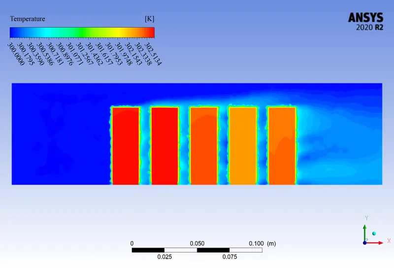
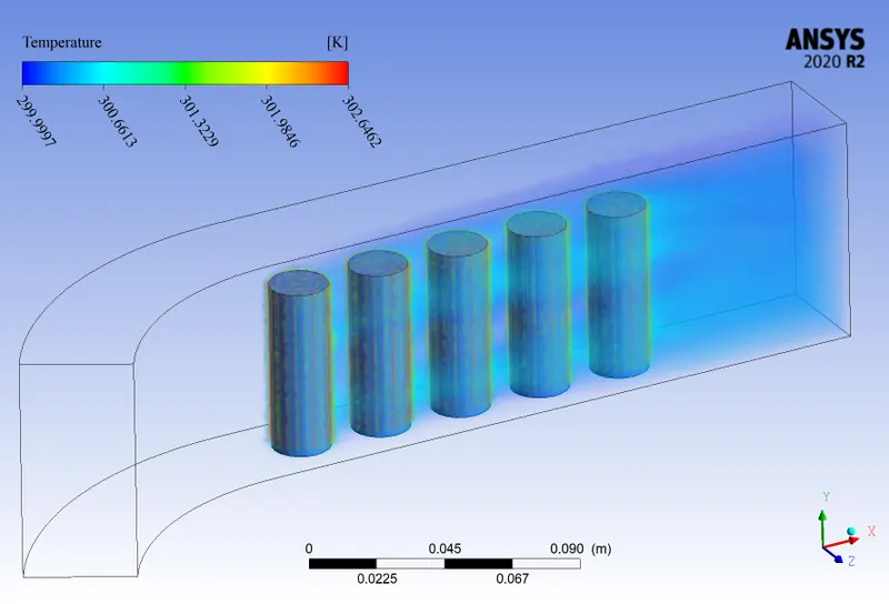
The Temperature value is shown higher in the cells due to internal heat generation. The airflow around the cells is also get heated and take away heat from it. But here we can see that the temperature of cells decreases respectively, this is due to the increase in the velocity of air due to a decrease in the area as discussed before.
The rate of heat transfer is increased due to the higher velocity of the air. the temperature of the battery is kept maintained which is good for the operation.
5.4 Convergence:
The Graph of Volume-Average of temperature shows Fluctuates between the temperature limit of 302.4000 and 302.6000 K for all the elements size 4mm. but for larger element size the fluctuation is larger due to the less accuracy in the calculation. because we know that as the size of the element is decreases the accuracy of the solution is increases.
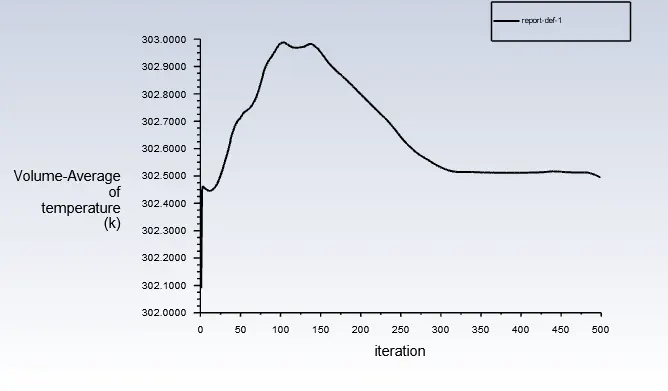
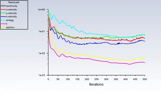
Here from the above plot, we can see that due to the size of the 4mm element, the mesh is refined and the accuracy is high but the solution is not going to converge even after 500 iteration. This is due to our medium is air and continuous heat generation. the air is not able to cool the system properly hence the fluctuation in the curves can be seen here.
Hence from all the results as discussed above we can clearly say that Air cooling is not a recommendable method to be used in the battery thermal management system due to its limitation. i.e it can not be used in hot weather conditions. it can be used only where the climate is cold. hence using the other cooling medium is more effective such as Liquid cooling.
Velocity Visualization:
Error Checking
The General procedure followed by the Ansys is getting a Differential form of governing Equation including boundary condition then it is converted into Integral form without any error. Now The integral form of governing equation and Boundary condition is converted into the Non-linear Algebraic Equation where relating cell center values. During this procedure, Ansys Calculates the convergence at each center by taking an average value of near about cell. In this step due to the average value, the error is occurs called Discretization Error.
Further, when the solver moves further from Non-linear Algebraic Equation relating Cell Center Values to Linearized Algebraic equation relating cell center values another error occurs called Linearization Error. next solver Solve iteratively and update guess till it gets convergence. where convergence occurs when Imbalance falls below the Tolerance value.
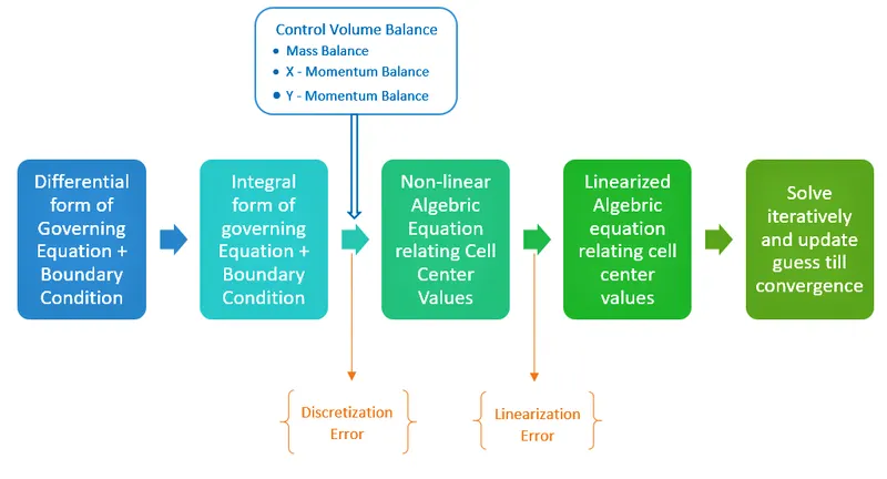
Discretization Error can be reduced by refining mesh and Linearization error can be reduced by increasing the number of iteration and convergence criteria. But note that Discretization Error is inversely proportional to the Linearization error.
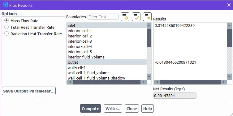
Checking Mass Balance
inlet = 0.0145
outlet = -0.0130
Error = 0.00147
Here we can see that we have a low degree of accuracy i.e we need to refine the mesh.
Further, We can integrate this simulation study with respect to liquid cooling for better results.
References:
Skill Lync course work
Battery Thermal Management Systems of Electric Vehicles (JILING LI ZHEN ZHU)
The Flow of report:-
1. Objective.
2. Introduction.
3. Pre Analysis.
4. Procedure.
5. Results and conclusion.