Preprocessing of car instrument dashboard panel using ANSA.
Aim- Preprocessing of car instrument dashboard panel using ANSA.
Keyword- Mid surface extraction, Meshing
Objective- To clean up the geometry of the model and extracting the mid surface then perform the meshing on the mid surface and give the thickness of the mid surface.
Quality criteria to be followed.
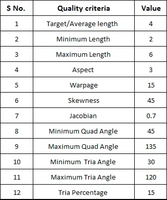
Abstract- In this project, The car instrument dashboard panel is taken for the pre-processing stage of CAE. This pre-processing stage is going to be done using ANSA software.Mid surface extraction and meshing will be performed on this model and all the steps were taken during mid surface and meshing are discussed here.
Methodology-
1- Cad file importing.
2- Geometry cleanup (Topology)
3- Mid surface extraction
4- Quality criteria setup
5- meshing and mesh improvement.
Introduction-
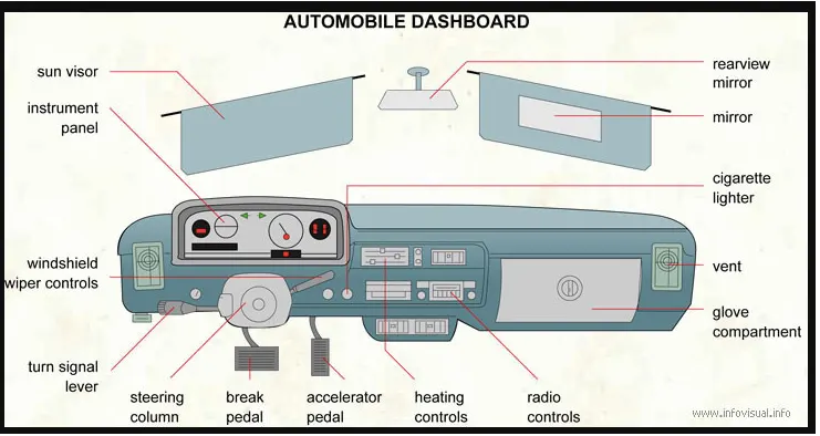
A dashboard is a control panel usually located directly ahead of a vehicle's driver, displaying instrumentation and controls for the vehicle's operation.
Where the dashboard originally included an array of simple controls and instrumentation to show speed, fuel level, and oil pressure, the modern dashboard may accommodate a broad array of gauges, and controls as well as information, climate control, and entertainment systems.
Contemporary dashboards may include the speedometer, tachometer, odometer, engine coolant temperature gauge, and fuel gauge, turn indicators, gearshift position indicator, seat belt warning light, parking-brake warning light, and engine-malfunction lights. Other features may include a gauge for alternator voltage, indicators for low fuel, low oil pressure, low tire pressure, and faults in the airbag (SRS) systems, glove compartment, ashtray, and a cigarette lighter or power outlet – as well as heating and ventilation systems, lighting controls, safety systems, entertainment equipment, and information systems, e.g., navigation systems.
Why should we work on the mid surface?
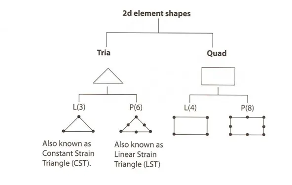
2-D Element-
When two of the dimension is very large in comparison to the third dimension is called a 2-D element.
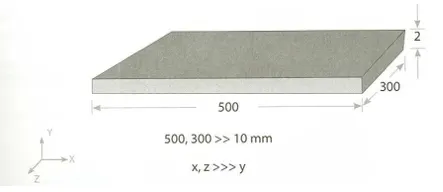
Why meshing should be done on the mid surface?
Midsurface modeling is a technique for creating a simplified shell representation of a solid model. Midsurface modeling can reduce the computational expense of analyzing a complete solid model when a shell model with a defined thickness and fewer details is suitable for the required analysis.
Procedures-
1- File Importing-
Here we importing the file from the file section and read it carefully. Apply the topology for proper view some time we can give length as 1 for the best view of the model.
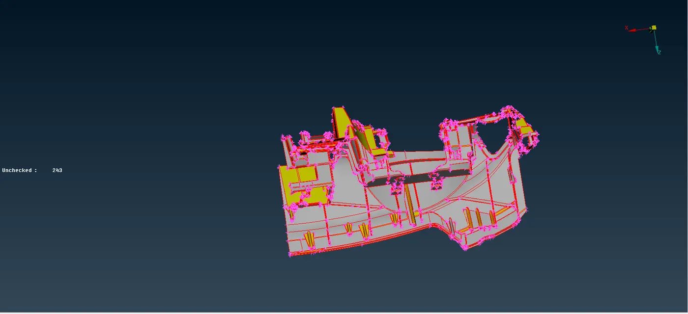
2-Geometry Cleanup-
After importing the file the first thing that needs to be done is geometry cleanup. There are various error will be shown when we execute the model for geometry cleanup( i,e- single cons, triple cons, crack, needle, etc), to clear these type of error three are two types of procedure to be followed-
1- Manual cleanup- In this procedure, we have to release the cons and apply the topo for triple cons, and for cracks and other errors some time we can delete the face and create the new face there.
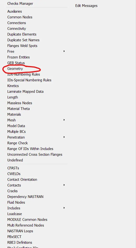
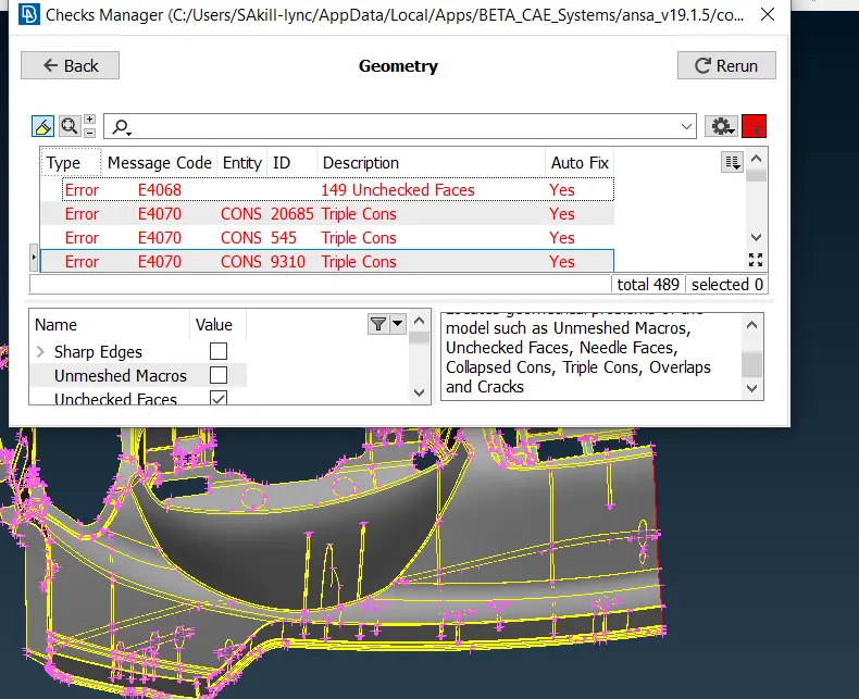
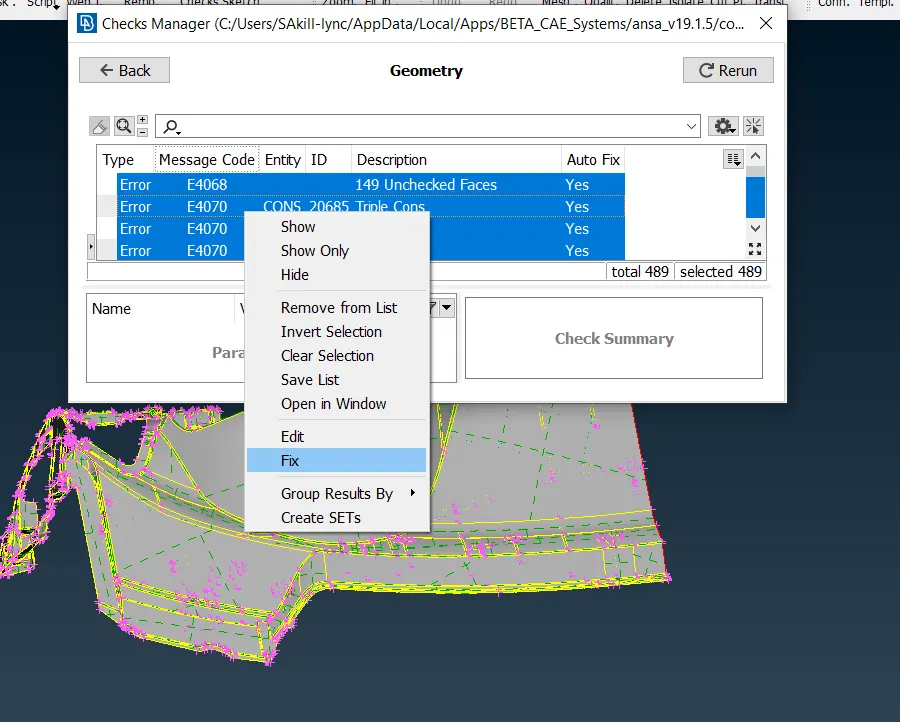
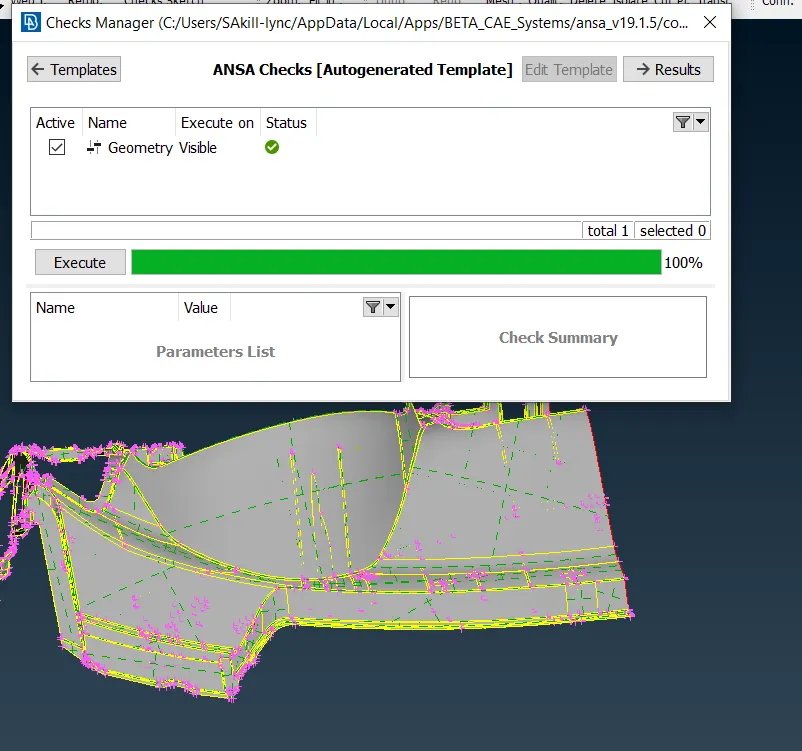
2- Auto Fix- For auto-fix, there is a command in which we can perform, select the error, and right-click and fix, it's a very effective way to save the time but some time auto-fix will not work so we have to work on a manual fix.
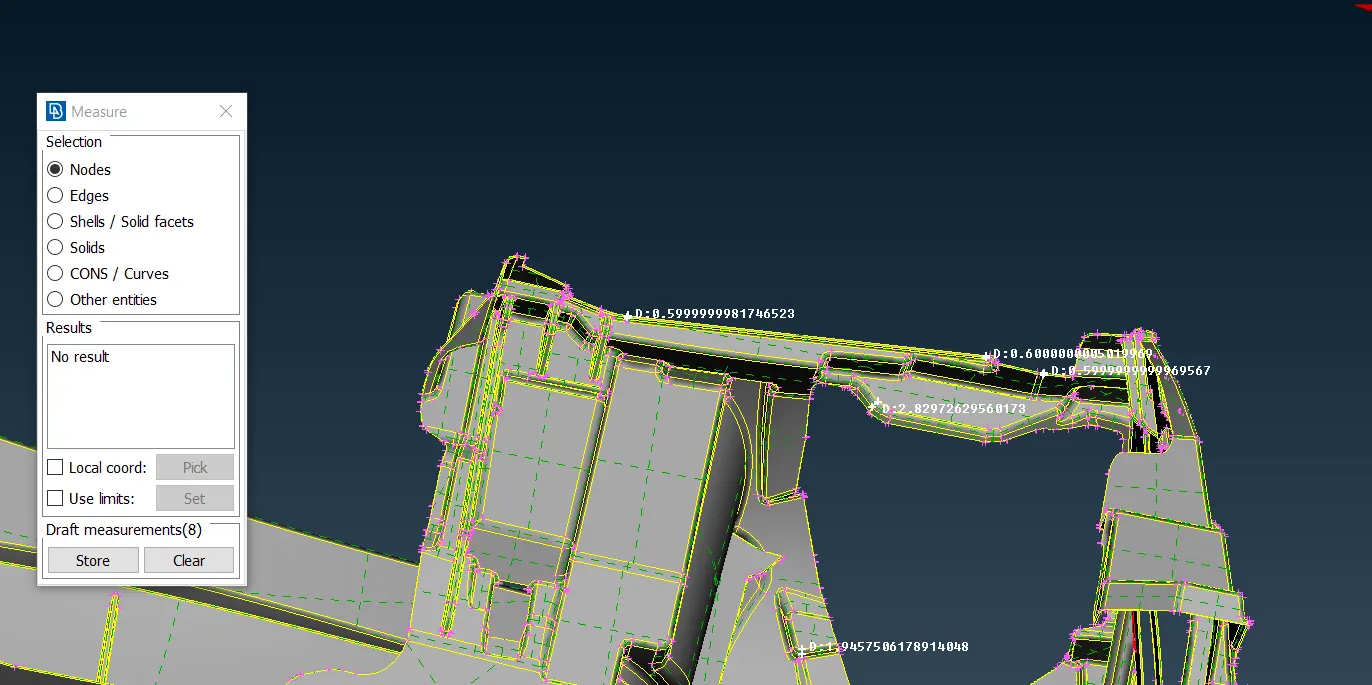
Thickness Measurement-
Thickness measurement is very important for mid surface extraction, it will be easy to take the offset of that part when we know the thickness [ Offset= -(Thickness/2) ]
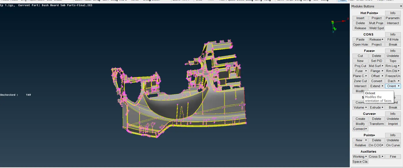
3- Orientation-
Performing orientation every time will help the user for proper view and help to take the mid of the geometry. The orientation issue can cause the error during the merging of the part with the whole model.
4- Mid Surface Extraction-
There are two ways to extract the mid-
A- Auto Mid-
There are module and command will have to use for auto mid extraction-
TOPO-FACES-MIDSURF-SKIN/CASTING
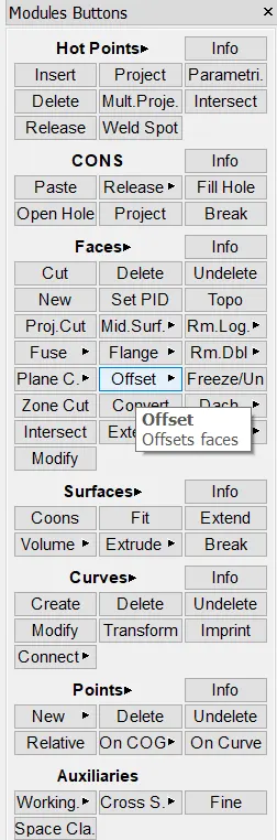
B- Manual Mid-
There are module and command will have to use for auto mid extraction-
TOPO-FACES-OFFSET- SELECT THE FACE
Sometimes we can not able to capture the whole mid surface, so for that, we need to create the new face on the mid surface to complete the model.
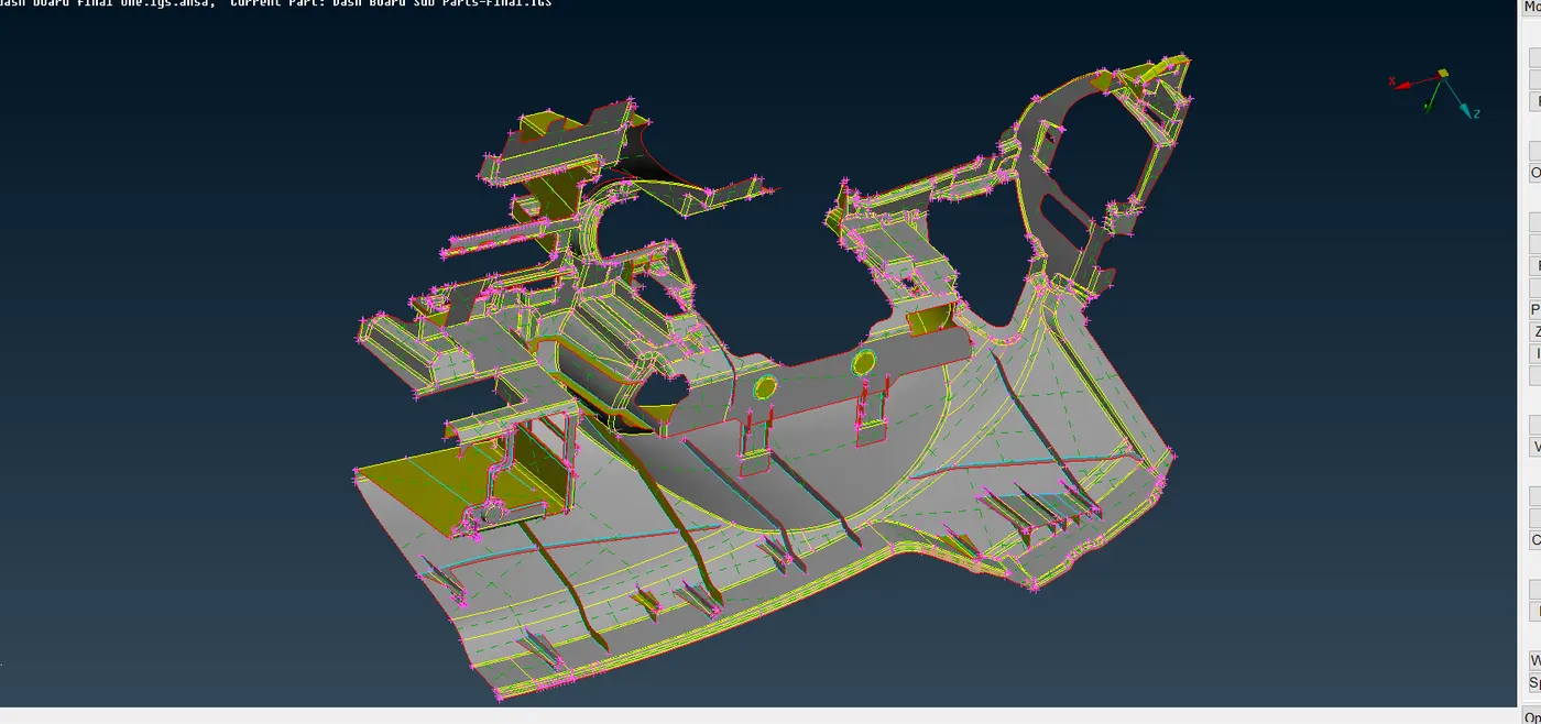
PIDs Assigning-
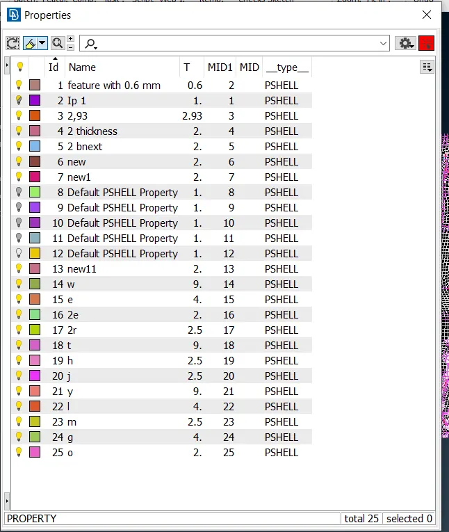
PID (Property ID) is given to different parts with different thicknesses, this meshing will easy on those individual parts.
5- Quality Criteria Setup-
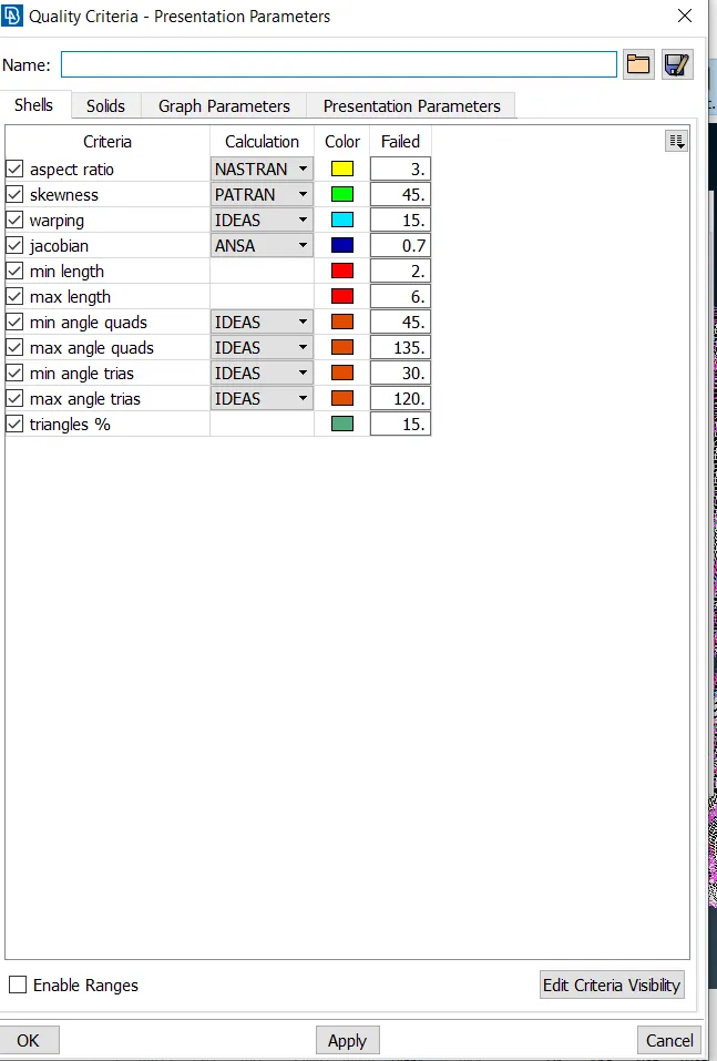
Before meshing we have to give some quality criteria for mesh elements, and mesh quality is directly proportional to element quality. There are various quality parameters we have to give for meshing.
A- Warp Angle-
Warp Angle (FEM mode) Warp Angle is a way to measure how far is a quadrilateral element from being planar. When you check your mesh, Creo Simulate uses the Warp Anglequality measures to highlight elements exceeding the maximum warp angle.
B- Aspect Ratio-
The aspect ratio of a geometric shape is the ratio of its sizes in different dimensions. For example, the aspect ratio of a rectangle is the ratio of its longer side to its shorter side – the ratio of width to height, when the rectangle is oriented as a "landscape".
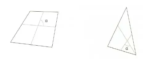
C- Skewness-
Skewness refers to distortion or asymmetry in a symmetrical bell curve, or normal distribution, in a set of data. If the curve is shifted to the left or the right, it is said to be skewed. Skewness can be quantified as a representation of the extent to which a given distribution varies from a normal distribution.
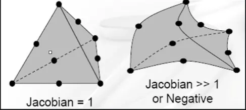
D- Jacobian-
It is a scale factor that is used in the transformation of the co-ordination system. The ideal value is 1 but grater than .6 is ok.
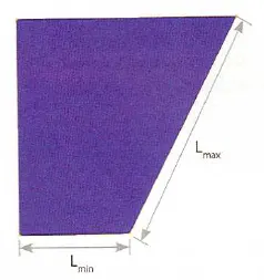
E- Min/Max Length-
It is important to check the min and max length of the mesh for the better mesh flow.
F- Target/Avg Length-
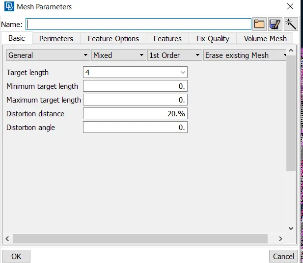
It is the size of the element so that we can get the approximate result nearer to the experimental result.
6- Meshing-
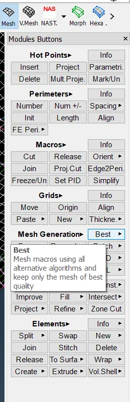
There are many ways for mesh generation which follow according to the requirment of the model, here we gonna perform the BEST mesh generation command.
A- BEST-
This procedure of mesh generation is generally used for one-shot mesh generation, which means the whole model gonna meshed at once and this mesh generation is only performed on the mid surface extracted part.
B- SPOT MESH-
Spot mesh generally uses for surface or solid mesh which is time taking and its meshing the model part by part.
C- BATCH MESH-
The batch mesh is also a one-time mesh generation process that can mesh all the model at one shot, it is the users' choice and model requirment to decide where to use the BEST mesh command and BATCH mesh.
NOTE-Here in this project BEST command will be used for mesh generation.
( MESH-MESH GENERATION-BEST)
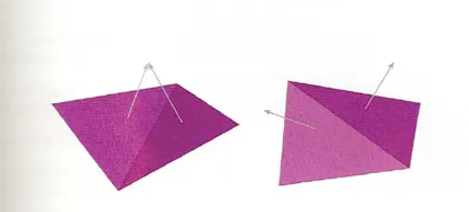
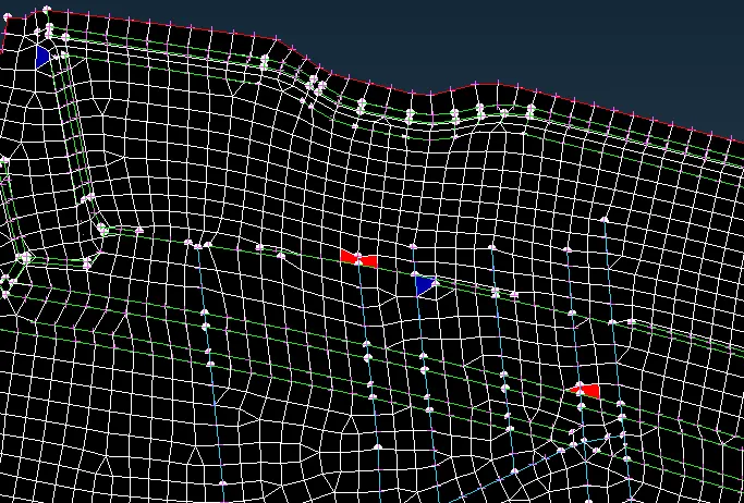
MESH WHICH CAN NOT BE ALLOWED-
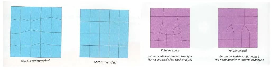
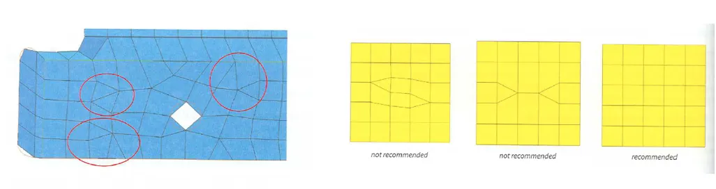
7- Difficulty In Capturing the Feature and Failing Elements.
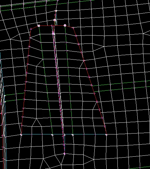
There are so many features that cant be capture easily so we have performed various techniques to take mid of those parts and also failing elements present in the geometry which can be improved b various commands.
8- Mesh Improvement-
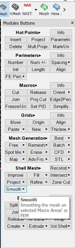
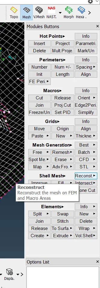
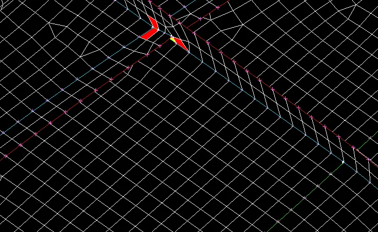
So as we saw there were so many failing elements present in the model, we need to improve the mesh using the various commands which presents in the MESH module.Reconstruct/improve/smooth/split/swap these are the command which used to improve the quality and reduce the failing element.
9- Meshed Part-
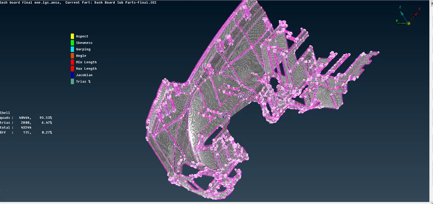
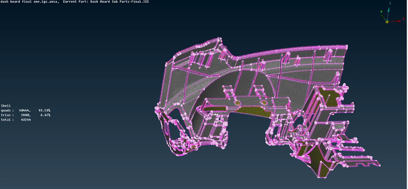
After mesh and performed some mesh improvement operation here we come with the final meshed part.
10- Final Part-
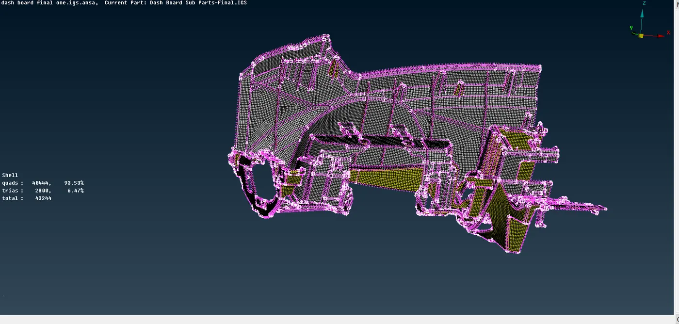
After assigning the thickness of different PIDs part we can on the DRAW SHELL AS SOLID option to assign the thickness and complete the modeling.
11- Module and command will be used in the project-
A- TOPO- ( OFFSET, ORIENT, NEW, DELETE, EXTEND, RELEASE, PROJECT )
B- MESH- (LENGTH, CUT, ORIGIN, BEST, RECONSTRUCT, IMPROVE, SMOOTH, SPLIT, SWAP)
12- Procedure in short-
1- Import the file.
2- Apply TOPO.
3- Give length as 1 for an initially better view ( It can be changed during meshing as per requirement).
4- Go for geometry cleanup and fix it.
5- Mid surface extraction. ( As per requirement command should be used)
6- Create a surface where proper mid not taken.
7- Check the geometry cleanup again.
8- Give the PIDs for individual parts if there are many parts present. ( Property ID can be checked)
9- After checking proper mid can go for meshing.
10- Give the quality criteria mesh parameter and other parameters for meshing.
11- Apply the mesh as per the requirement of the model.
12- Check for quality issues and fix if any.
13- Apply DRAW SHELL AS SOLID to assess the thickness of the part which will apply according to PIDs.
14- Here our meshing is completed.
11- Conclusion-
The part has been well captured and meshed according to the quality criteria given. The total element 43222 out of which 40424 are quad element and 2709 trai element which is 6.47% which is quite good for the quality. There re also 115 failings (off) elements where the capturing of faces is too hard and the construction line is crossing each other. The mesh flow is nearer to the target length which is given as 4.
12- Learning Outcome-
a- Able to clean the geometry and fix the geometrical error.
b- Able to extract the mid surface.
c- Have learned about 2-D elements Shell Meshing (TRAI and QUAD element)
d- Aware of quality criteria during meshing.
e- Able to mesh (2-D/Shell mesh ) on the normal parts as well as complex parts.