Project 1
Aim
To check the given industrial project for geometrical errors and to mesh the same.
Procedure
Step -1 Study of the model:
- The model assigned was a dashboard. Dashboard is one of the main trim components in the car.
- The dash board is a complex plastic trim with many supporting ribs, mounting points and other types of features.
- The thickness of the parts were varying according to the needs .
Step -2: Standard geometry cleanup.
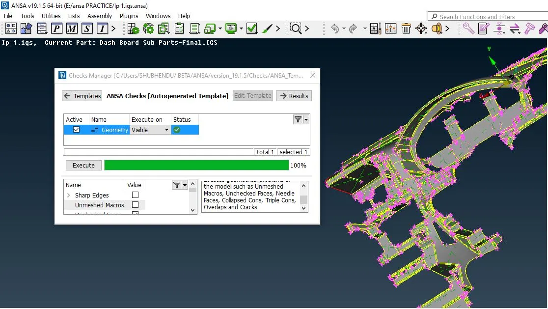
- The model had very little issues.
- Most of it was fixed automatically using the FIX option from the geometry checks manager.
- The rest of triple cons were removed manually.
- Then it had many damaged surfaces it was deleted and new surfaces was created.
- Then the model was ready for the mid-sufacing.
Step-3: Mid-surface preparation.
- The model was a single entity with different features and thickness. So the mid-surface was prepared individually for each part.
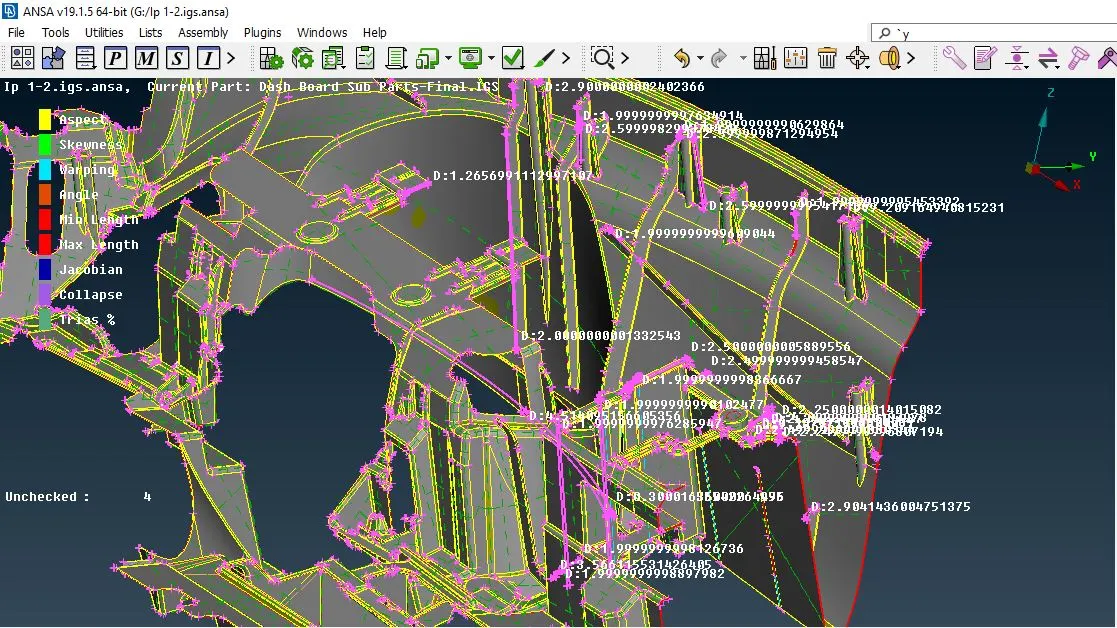
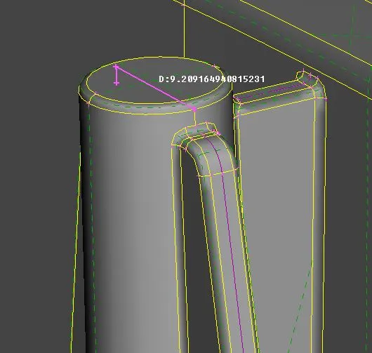
- Thickness of the parts was measured and mid-surface was made using offset by using offset option.
- Skin selection was done using feature area selection. Hence each part was mid-surfaced in one shot.
- The largest portion was the main surface with thickness of 0.6 mm. it was mid-surfaced in one shot using offset option.
- Then the mid-surfaces was checked or cons that would result in bad mesh.
- Such cons were joined and some were introduced to capture features.
- Then it had many damaged surfaces it was deleted and new surfaces was created.
- The mounting points were mid-surfaced by offsetting the surfaces to distance of the half the radious. So the surface when given thickness would imitate the solid.
- The ribs were created by tracing its profile by creating the curve using 'MIDDLE' in curve tab, on the top-surface of the rib to get the height. Then the midsurface of the rib was created by taking middle of the rib using middle option in faces tab by selecting opposite surfaces.
- Then the edges of the middle-surface were projected to the attaching points of the ribs to surface. Now the middle surface was deleted and the cons were connected to the curve to give required middle-surface.
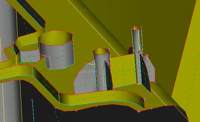
- Each feature was captured and then joined together by topo.
- Then the triple cons were created at attachment of various features.
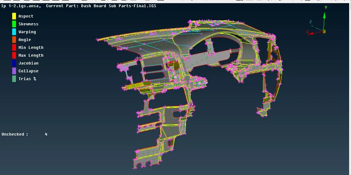
Step-4: To type in the quality criteria.
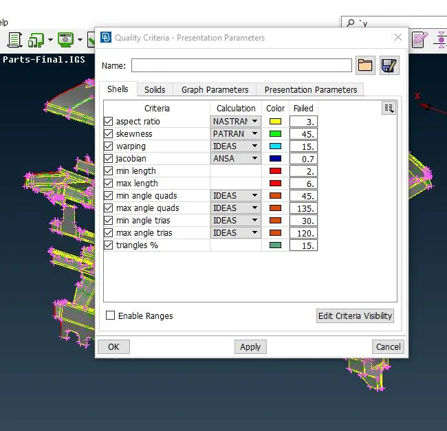
- The criteria’s were typed into the mesh parameters and quality criteria tab.
- The max-length was 6mm, min-length 2 mm and target was 4mm.
- The type of mesh id mix of quads and trias.
Step-5: Meshing and checking.
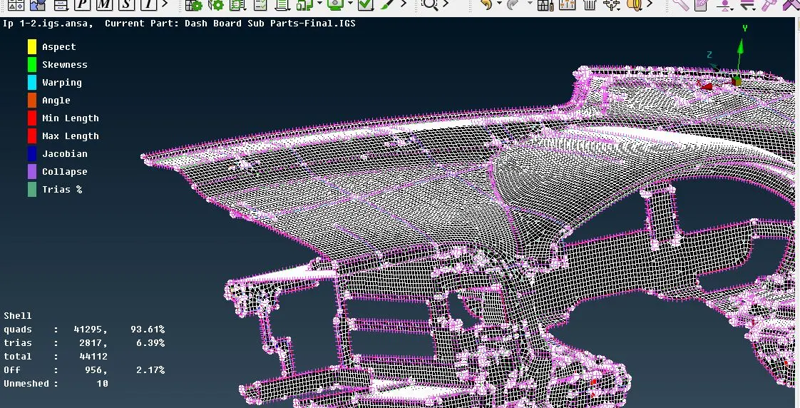
- Then each part was selected and meshed according to the needed quality individually.
- The mesh was checked and reconstructed to ensure a good mesh flow.
- The number of trias were reduced using split, swap and paste options.
Step-6: Giving thickness to shells
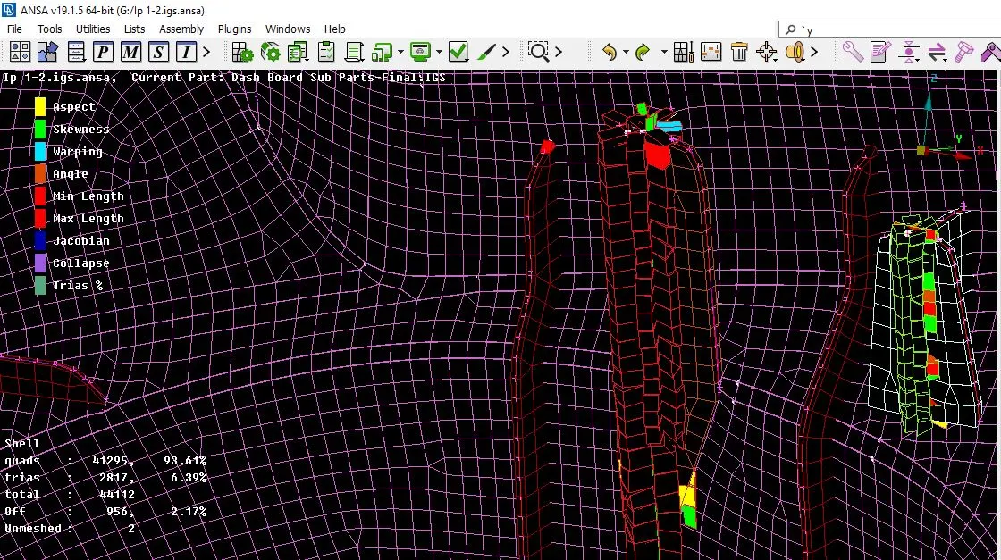
The mid-surface with connection were given thickness by going to presentation parameters and enabling drawing shell as solid option.
Conclusion
The industrial project ws succesfully completed according to the quality criteria. This project gave an insight how the actual industry functions.
https://drive.google.com/file/d/1dg20_vrDgulinWSQtp0cqbP3zFY2xuL8/view?usp=sharing