For NVH simulation performed 2D Finite Element meshing over Dashboard (plastic model)
Aim: - To perform 2D Finite elemental Mesh on giving plastic model, and ready the model for NVH simulation on the ANSA Workbench.
Basic Steps
1) Import the model and Go for Length option from the mesh module to find out the actual geometry of a model
2) perform topo on it. As the model is too distorted after importing from different software.
3) After understanding the geometry, we can go for mid surfacing,
4) Extract the MID surface and assign PID as per their thickness.
4) After mid-surfacing we can go for 2D Finite elemental meshing by setting the Quality criteria.
5) Solve the Quality issues generated during meshing and move forward.
6)Assign property to each section.
7) In the end, just assign the thickness.
IP substrate
A dashboard (also called dash, instrument panel (IP)) is a control panel set within the central console of a vehicle. Usually located directly ahead of the driver, it displays instrumentation and controls for the vehicle's operation.
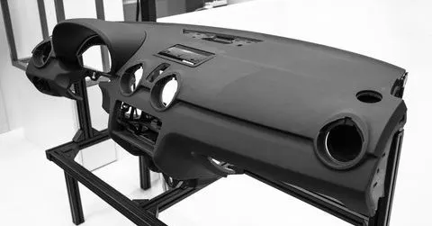
This Instrumental panel is very important not only because it will provide information to the Driver about Vehicle condition but also deform during the collision and protect Driver and occupant.
It contains an Information panel, Infotainment system, AC vents, Storage Compartments, safety gear (Airbag mounting for occupant next to the diver), etc.
Procedure
I imported the given component as known as IP substrate (Dashboard). This is actually a plastic component and as we all know the plastic components have different thicknesses throughout their whole geometry.
As you can see that the geometry is in bad shape and it’s hard to figure out the actual geometry/shape of the component.
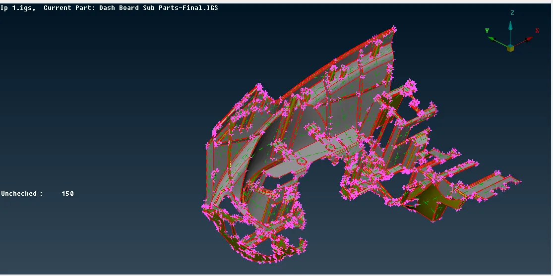
Fig 01
So, the first thing we can do here is to understand the geometry. I the Mesh module there is an option of Length. The length option sets the perimeters node distance minimum to get a better picture of actual geometry.
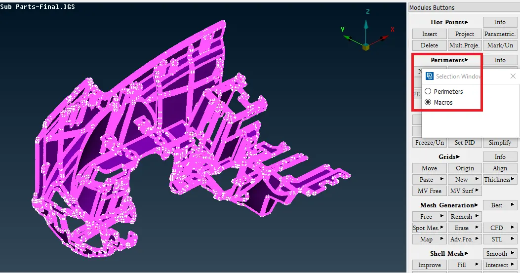
Fig 02
Here, you can see the selection window which will pop up after clicking on the Length option, and using the Perimeter and Macros option we can set the distance between the two nodes to get a better view of model Geometry.
The next thing I did was performed a Topo operation on the model using the topo Module. What Topo does is it basically connects all adjacent surfaces/ singe cons and completes the geometry.
As you can see below image After performing the length and Topo, I get the result like this.
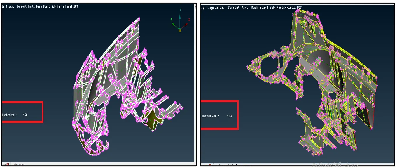
Fig 03
As you can see in the above image all the single cons (Red lines) replaced with double cons (Yellow lines) means the topo operation was successful.
One more thing to be noticed is the number of Unchecked surfaces. It was 150 for the newly opened geometry but after TOPO operation it was reduced to 134. As you already get the idea that the entire geometry of the IP cluster is not available here, and only half a portion is provided so some of the unchecked surfaces may be due to the partially open end of the Geometry.
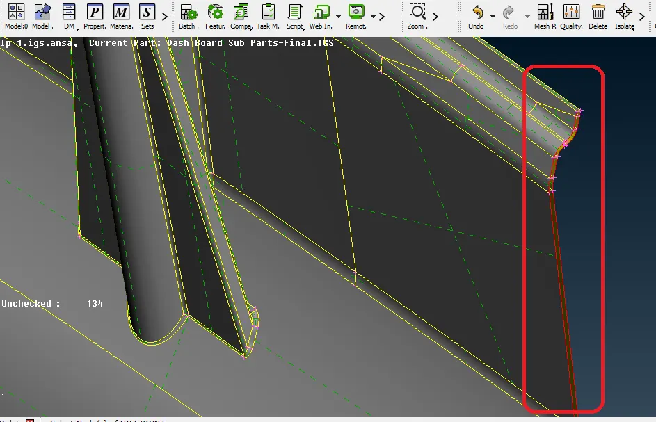
Fig 04
I had closed that open surfaces by creating new surfaces in between, but there are still some errors. To identify and remove those errors I had performed a Geometry Check.
Geometry Check: - It’s the operation with which we can identify the different types of errors in Geometry. It was preferred to do a Geometry Check and clean up on the model before proceeding with MID surface extraction.
Types of errors generally occur in the model
a) Triple con: -Triple con error occurs when more than two surfaces are stitched together.
b) Needle Face: -These are the small surfaces generated in the model to satisfy the geometry.
c) Crack between cons: - these errors generally are very small cracks in the geometry. These cracks are very small to identified therefore it's better to go with the auto-fix option.
d) Single cons: - The above image is a good example of single cons.
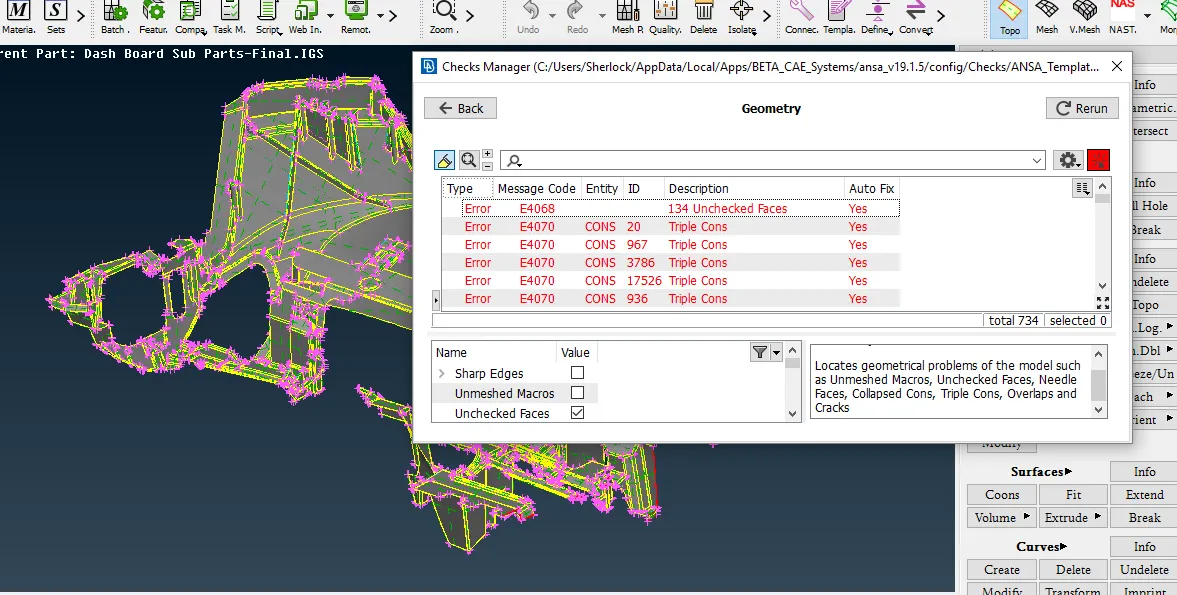
Fig 05
To get rid of these errors there are two methods one is annual and the other one in an Auto fix.
I had used both of these methods to remove all the errors from the Geometry.
The reason I used the Auto fix because this model is too large and complicated. It had nos. of ribs and locator pins. So basically, identify and remove these errors by only the manual method is time-consuming.
Even though I had used Auto fix to remove the errors there are still some errors in the geometry that I had to take care of Manually.
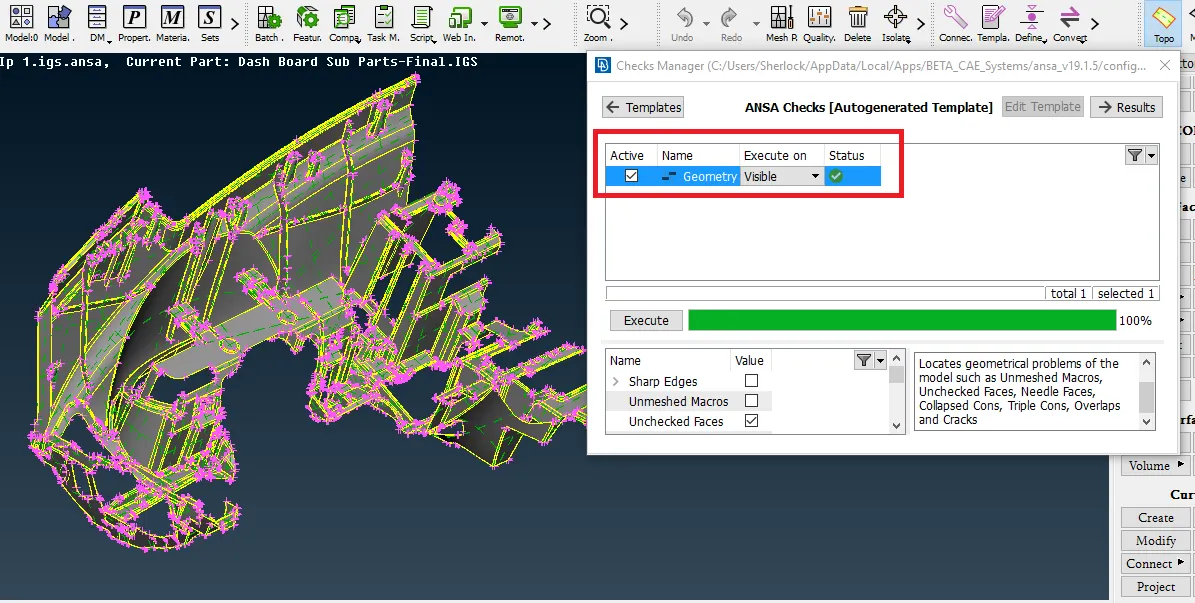
Fig 06
After cleaned the geometry, I had moved to the mid-surfacing. For this IP model I had gone for the surface by surface, as at the different stages of the model, the thickness was varying.
After extracting mid-surface, I had saved them into separate PIDs as per their thickness.
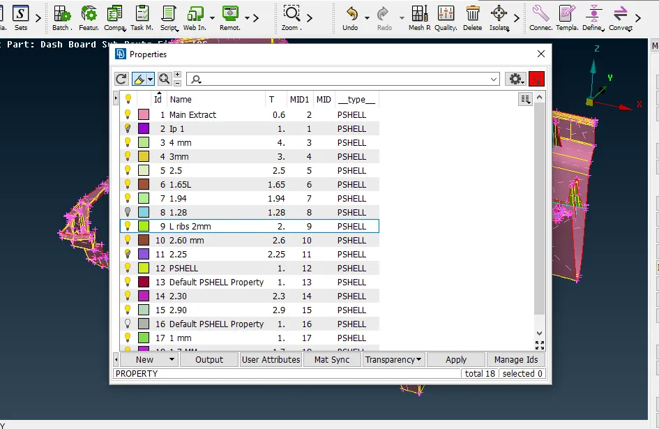
Fig 07
After done with mid-surfacing I had performed a geometry check on the extracted mid surface. There I also faced some errors. (Here I excluded single con check as complete mid geometry didn’t have any thickness)
I would discuss those errors in the next segment.
After clear out the errors (Some with auto fix and some with manual) I had moved to defeaturing.
Defeaturing: - It’s the process in which we have to compromise on some feature, have to capture them with some other means so they won’t fail for quality issues. In Some cases, depending upon which type of simulation the model falls under, the engineer has to decide which feature should be important for that particular simulation and on which he can give up. Defeaturing is as important as mid-surface extraction because without defeaturing the model has high chances of failure in different Quality criteria. And as a golden rule of 2D finite elemental meshing Engineers can't pass the model with more than fix quality issues for the simulation.
Here are some defeaturing examples,
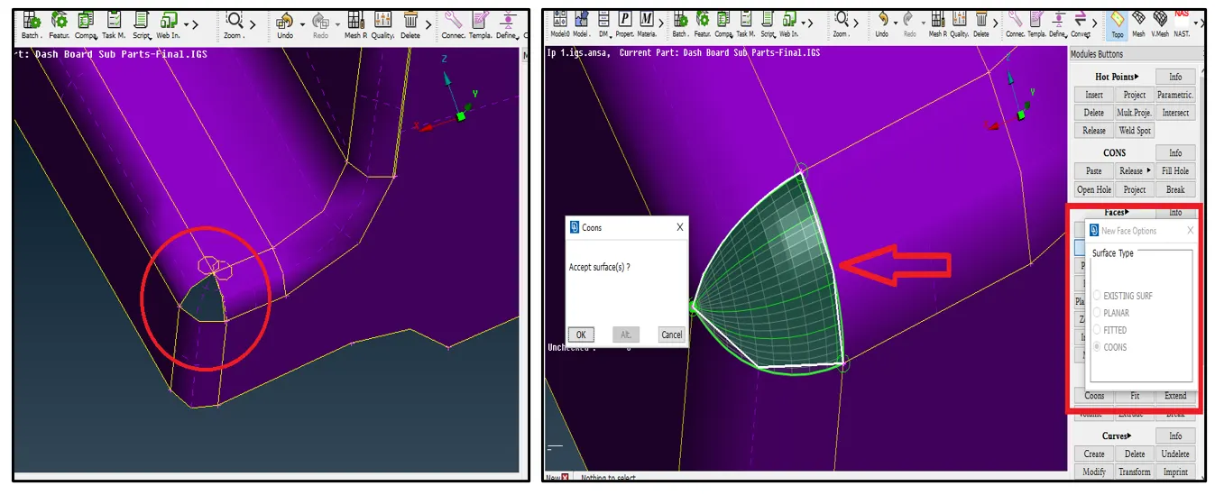
Fig 08
As you can see in the above image the surface did not get capture in a proper way during mid-surfacing, so it was mandatory to delete that face and create a new one which is more uniform. I had used Faces -->New option to create a new face.
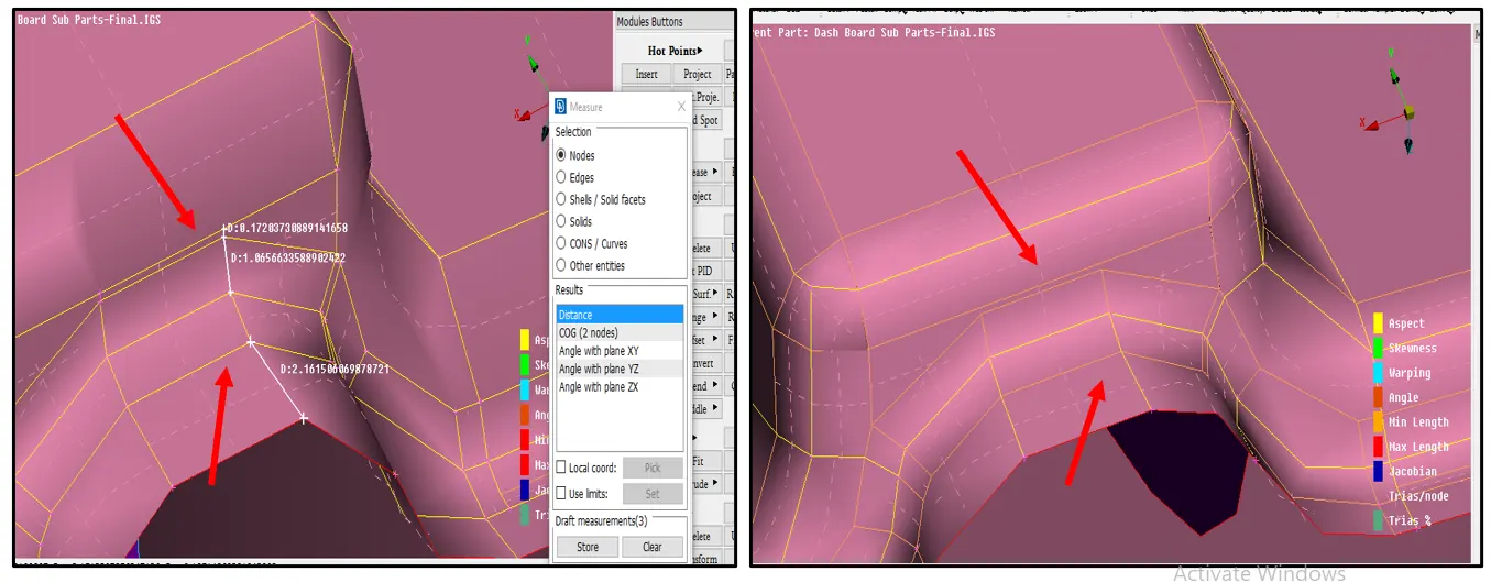
Fig 09
In the first image, the distance between the construction lines is 0.172, 1.06 which was less than the define minimum length criteria (2 mm). This means the 2D elements will definitely fail here because of the min, length criteria. In the second image, you can see that I had done defeaturing to avoid that.
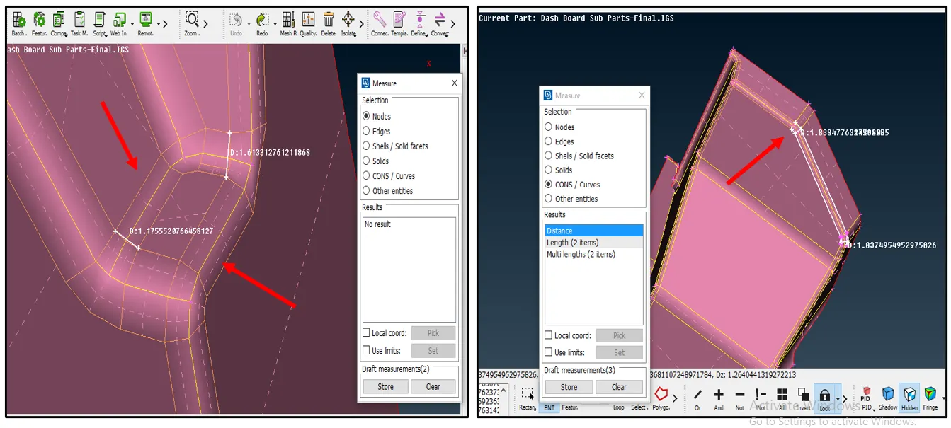
Fig 10
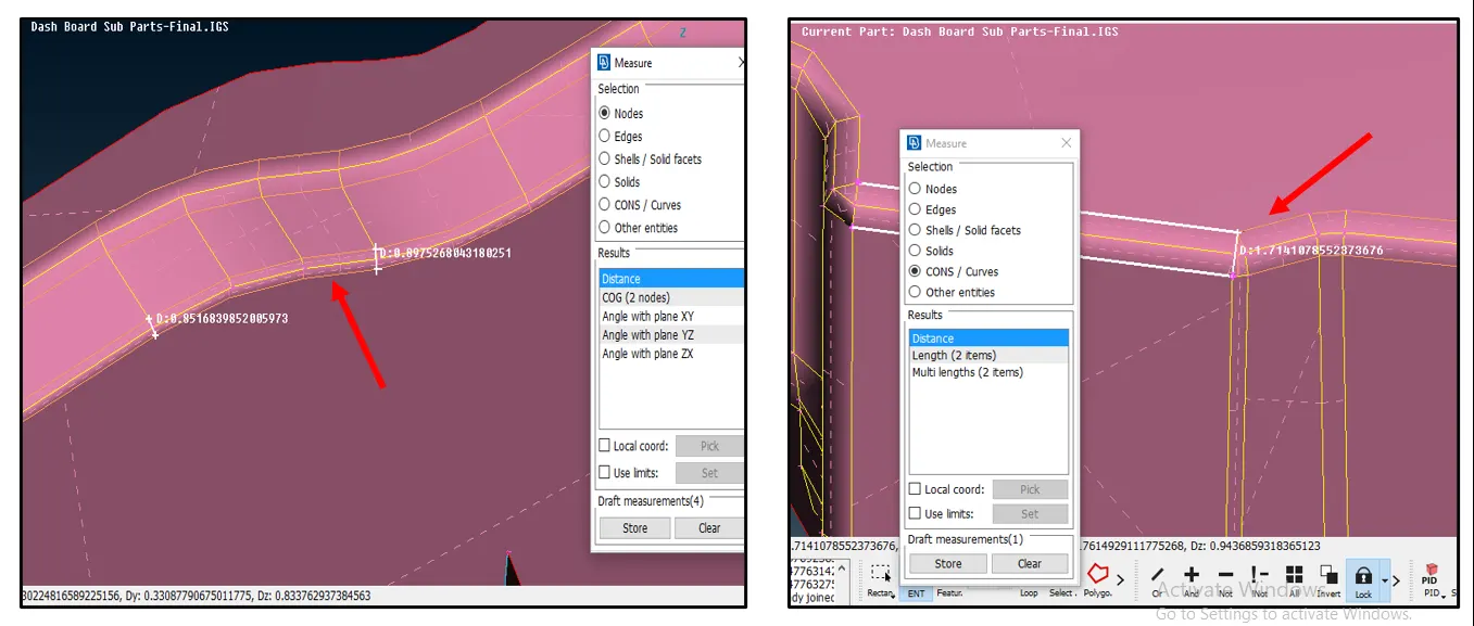
Fig 11
After done with defeaturing I had moved to the meshing. First, I had set the quality criteria and start meshing on the model. Here I also face some quality issues even after defeaturing but that is obvious.
The end result of 2D finite element Mesh is as follow,
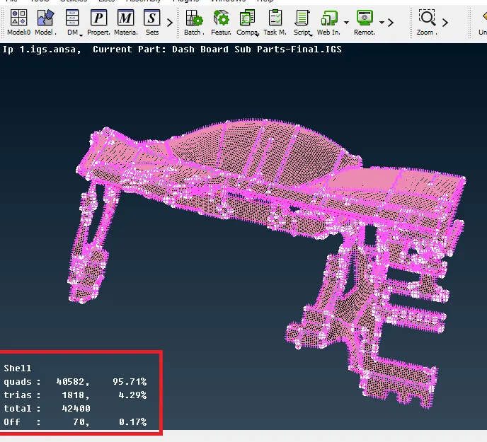
Fig 12
The finished model has 70 OFF elements which are 0.17% and trais of 4.29% which are acceptable because this is the tolerance given to me by respective seniors.
These OFF elements are because of the rib connection to their neighboring surface. The examples are as follows,
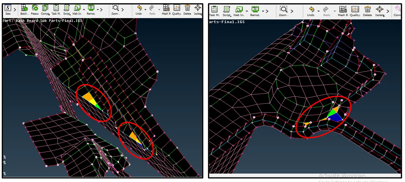
Fig 13
These off elements are very difficult to remove and as the Ribs are major features in this model, we can’t to more defeaturing on them. They are the strengthening elements here.
Also, I had to capture the ‘dog house/ locator’ (a cylindrical feature) as you can see in the below image as the 2d entity,
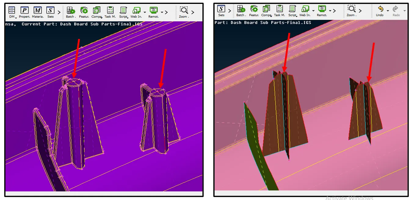
Fig 14
Errors
Here are errors had face after mid surface extraction
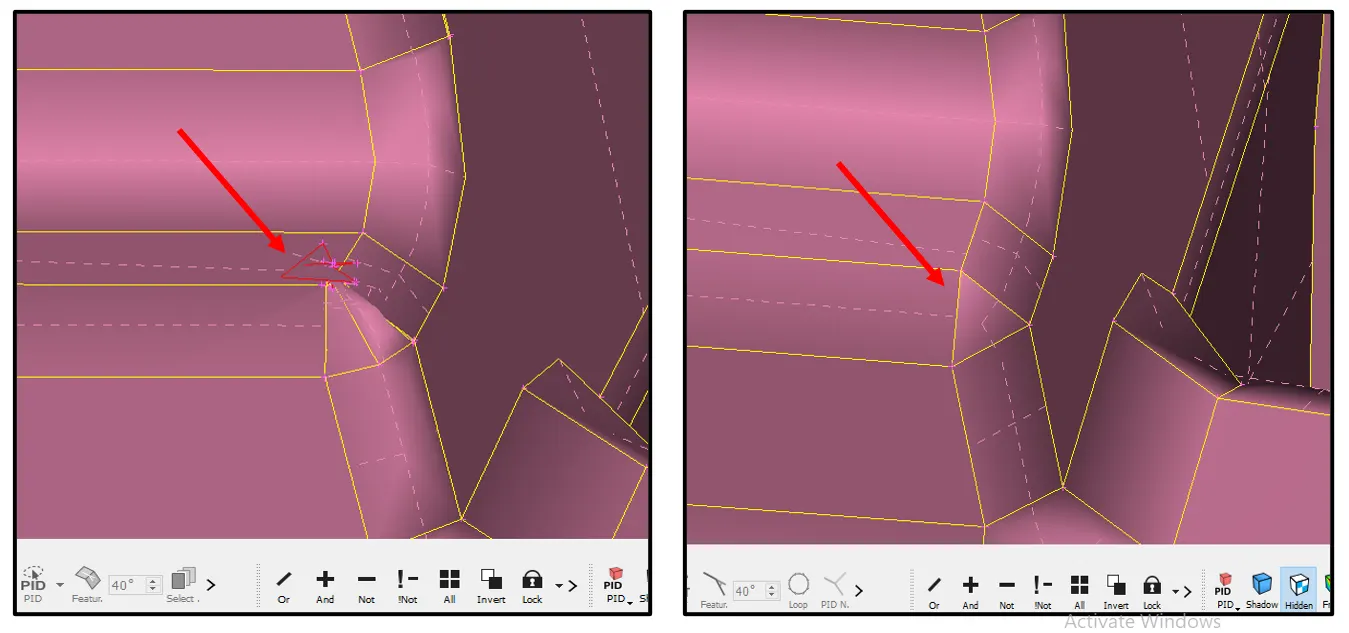
Fig 15
Here I had deleted the distorted face and create a new one by using topo deck options. This was an unchecked face error.
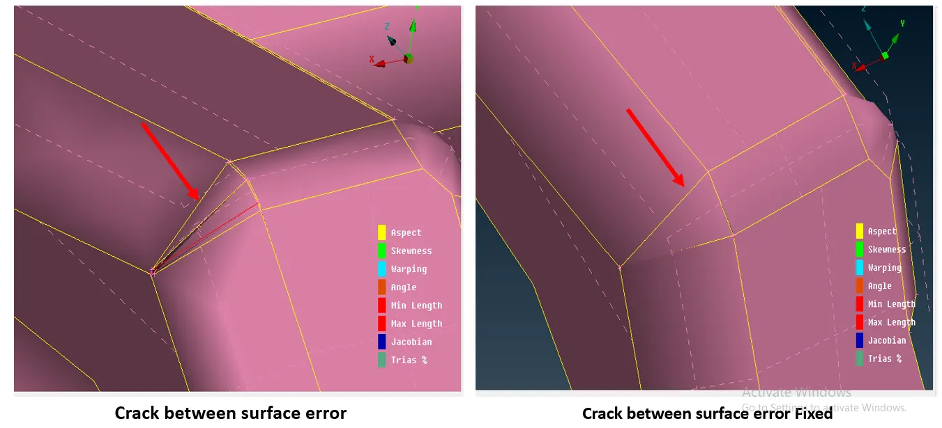
Fig 16
I also came across some triple cons errors which I had cleared manually.
Errors during 2D finite element Mesh
The errors show in the Fig.13 was also included as Mesh errors.
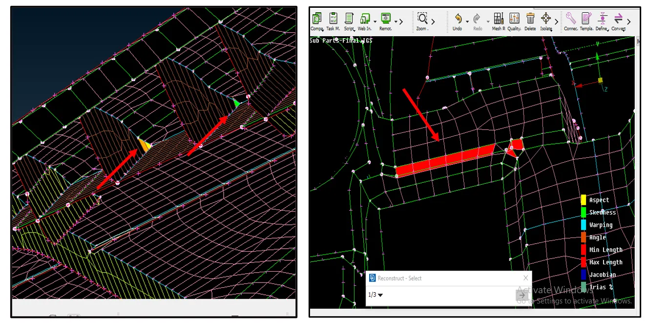
Fig 17
For the errors in Fig 13 and fig 17 first one, I get clearance from the instructor as they are unavoidable, and for the errors in fig 17 second, I had used a reconstruct / split/ swap /smooth option. (The elements here are failing for Max length Quality criteria)
I had face such quality issues in some parts of the model also the warpage, jacobian, and aspect ratio failure are there I had removed all possible errors using 2D mesh deck.
Conclusion
- It is difficult to extract the Mid surface in the plastic model because of its overall uneven thickness.
-- Sometimes engineer has to decide which feature should be important and which are not as per the simulation module and perform defeaturing
- Because of the complex geometry of the plastic component, it will take more time for meshing also.
- Unlike sheet-metal, Triple cons are important when the working component is of plastic/casting one.
- We can go with the minimal OFF elements if they are unavoidable but only if that sort of instructions is provided. (Many cases limit of trias and OFF element are set before start working on mesh)