2D Meshing of Instrumental Panel of car
Aim
Using the method os 2D meshing to mesh the Instrumental panel of an automobile car
OBJECTIVE
The given component is a Instrumental panel model of a car. This part is a plastic component and so that thickness is varying . So instead of going for 3D meshing, We can go for 2D meshing. For that we need to extract the mid ssurface .for extraction of midsurface ,we can make use of middle face option and offset face option .In middle face option we select two surfaces and the ansa will gave us the mid surface of those faces .Similarly in offset faces option we are offsetting the face to the mid region of the thickness so that approximate midsurface can be extracted.And at the end we wiill be stiching all the faces and acheive the midsurface of the complete IP and then we will be 2D Meshing it.
WHY we carry out meshing?
The answer is because the original component is having infinite number of atoms in it and when we apply any force the displacement or strain is happened to each and every atom inside it. But infinite number of displacements to find out is impossible. So we need to make the calculation finite, for that we divide the component into a finite number of elements having finite number of nodes. Most useful and popular 2d elements are quad and trias. Trias are being stiffer compared to quads they hesitate to transfer the force applied on it to nearby nodes so they are to be needed to minimize in the meshing process. Each element is having lines at the outer boundary which is based on the specific shape function of the element. We can find out the values of stress and strain at the nodes of the elements. Since we know the shape function of the element we can find out the displacement and stress values at the particular x and y as we need using the shape function.
For QUAD4 element shape function is u = a0 + a1x+a2y+a3xy.
FEA will calculates the values at nodes ,ie = a0,a1,a2,a3 Value of the variable in between nodes can easily be find out using the above shape function. Each element will have several degrees of freedoms. Degree of freedoms is the number of variables with which the position of a node can be represented perfectly. Mostly the total number of degrees of freedom = total number of elements x 6. Since the 3 linear motion and 3 rotational motion along x,y,z axis are possible for each and every elements. Then the degree of freedom also depends on the type of analysis we are to be carried out, Type of element we used in meshing process. Higher number of nodes in the mesh means higher accuracy. But the computational time will be high. Computational time is directly proportional to nth power of the Degree of freedom, and n = 1 to 4 depending upon the solver we used for analysis.
Dashboards may include the speedometer , tachometer , odometer, engine coolant temperature gauge, and fuel guage, turn indicators, gearshift position indicator, seat belt warning light, parking-brake warning light, and engine-malfunction lights. Other features may include a gauge for alternator voltage, indicators for low fuel, low oil pressure, low tire pressure and faults in the airbag systems, glove compartment , ashtray and a cigarette lighter or power outlet as well as heating and ventilation systems, lighting controls, safety systems, entertainment equipment and information systems, e.g., navigation systems.
First step in 2D meshing is to open the ANSA software .Then we need to import the IGES file which is the CAD file of instrumental Panel.
The CAD model needs to be imported into the ANSA GUI.This is done by File>Open>select the CAD File>open.Then the CAD file will be opened in the ANSA.Since the platforms are different for CAD and CAE.There will be so many translational issues in the model imported,So we need to first topologically cleaned up the component.To topological clean up of the model we need to stay in TOPO Module and use the necessary options in the TOPO Module.
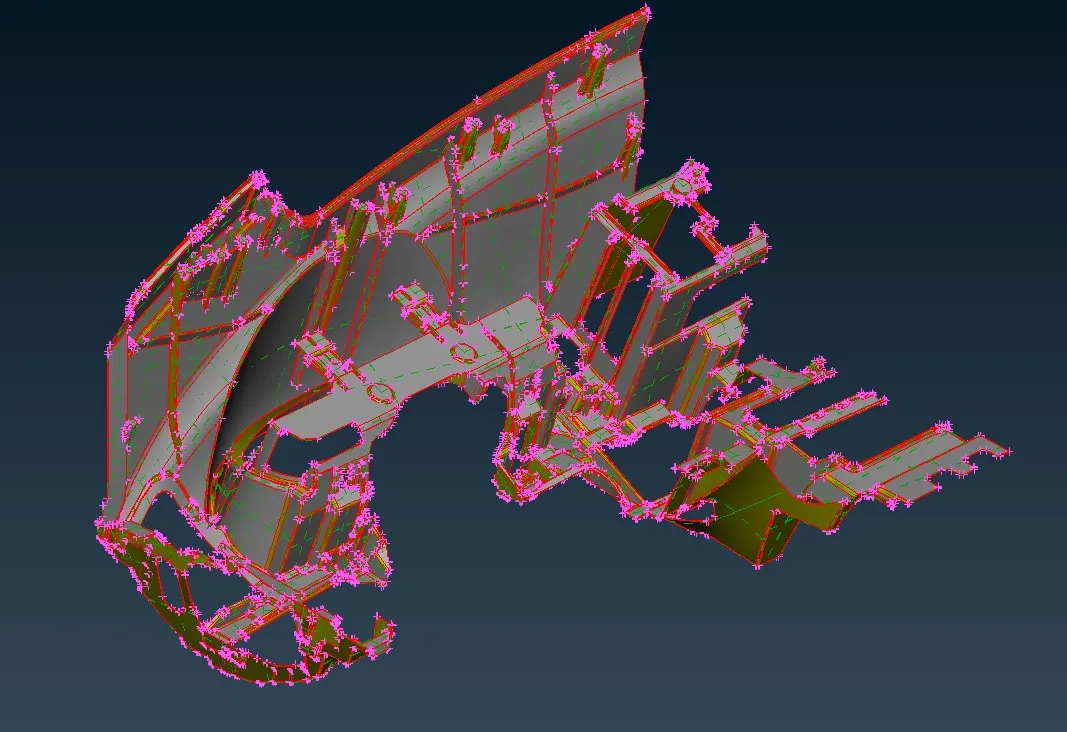
Fig 1 Instrumental Panel model before Topological claean up
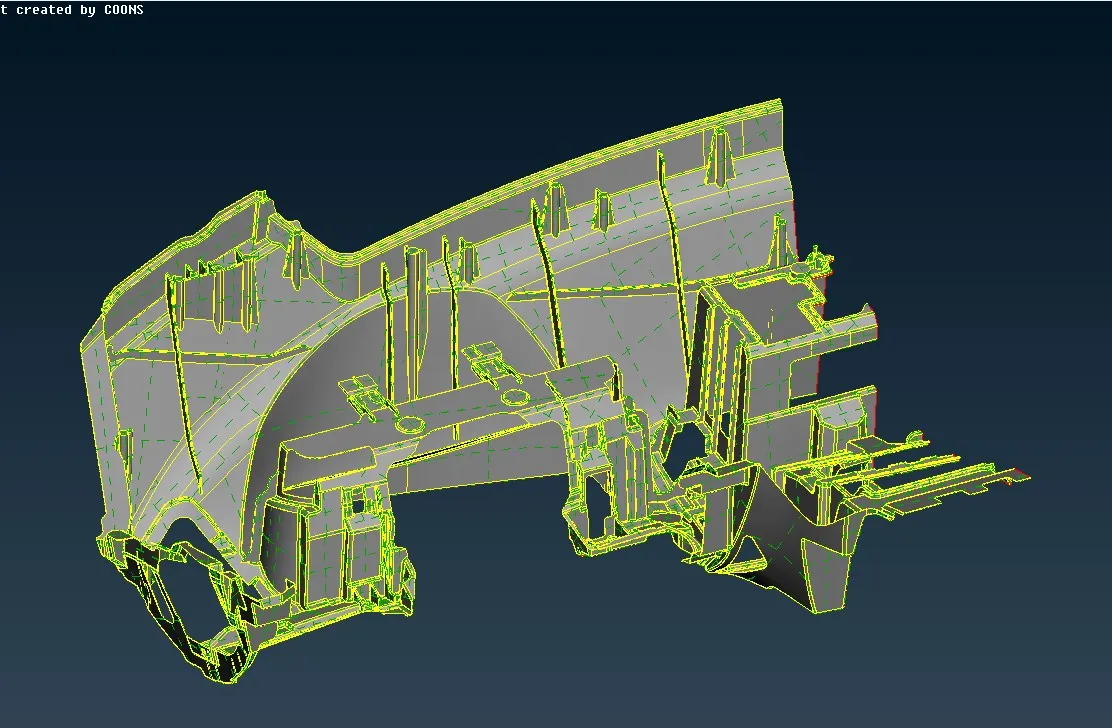
Fig 2 IP Model after Topological cleanup
Before that check the topological errors occurred due to the platform change by the use of check manager in ANSA.For that go to Check Manager>Geometry >Execute.It will show up the topological issues in the Model.We can go to each part and rectify the issues.The options used are
CUT : This is used to make the lines in the model which will divide the entire model.Face>New>Fitted>select the cons of the geometry to be created.
Zone cut is used to provide washers about the small holes.
Taking the midsurface of the plastic component is a hectic task and there where we spend most of the time in meshing.Before extracting the midsurface we need to check the thickness of the Instrumental Panel at everyplace.And from measuring we can see that the thickness is varying across sections and also it is varying in the features as well.We can start taking the midsurface using the FACE> MIDDLE > Select the surfaces we need to take the middle of>Middle click confirmation, this will give us the middle surface of the selected faces.in this way we can extract the middle surface of the majority of the portions including the ribs features.And in some places we need to create the middle curve using the cons of the features and later we will be joining the middle curve for extraction of midsurface of features like threads.For taking Midsurface we can use Curves>Middle>select one con >middle click >select second con>Middle click>This will gave us the middle curve of the selected cons.Most of the features in the model like ribs and trapzoidal wedges and all are symmetric and arranges at a particular angular offset in the model,so we can extract midsurface on of the feature and we can use the Rotate option to arranged the midsurface at exact place it will be if we extract midsurface of each manually.For that we need to extract the midsurface of the feature >Select the transform>Copy>Select the extracted midsurface of the feature>Choose the option Rotate>Assign the Angle correctly>Choose a normal axis using two points>choose middle click or press OK>This willl give us the midsurface of similar features arranged at its correct place in the model.To extract points at centre we can make use of COG option in points.POINTS>COG>CIRCLE> choose a circle >then this will produce a point at the exact centre of the circle. After completing with the process of taking the midsurface of the feature and faces we need to connect them .This can be done using the extend option and intersect option.
For that we can select the extend option in FACES >EXTEND>SELECT THE CON OF THE FACE WE NEED TO EXTEND>SELECT THE SURAFCE TO WHICH WE NEED TO EXTEND THE SELECTED CONE>MIDDLE CLICK.This will accurately produce the cyan con at the intersection if we select the surfaces correctly to which we need to extend while using extend option.Otherwise the surface may be protruding out of the surface to which we need to extend.In that case we need to use the intersect option in Faces.FACES>INTERSECT>SELECT THE SURFACE WHICH ARE INTERSECTING>,MIDDLE CLICK> THIS WILL SPLIT UP THE SURFACE AT THE INTERSECTION.So we can manually the delete the protruding surface.
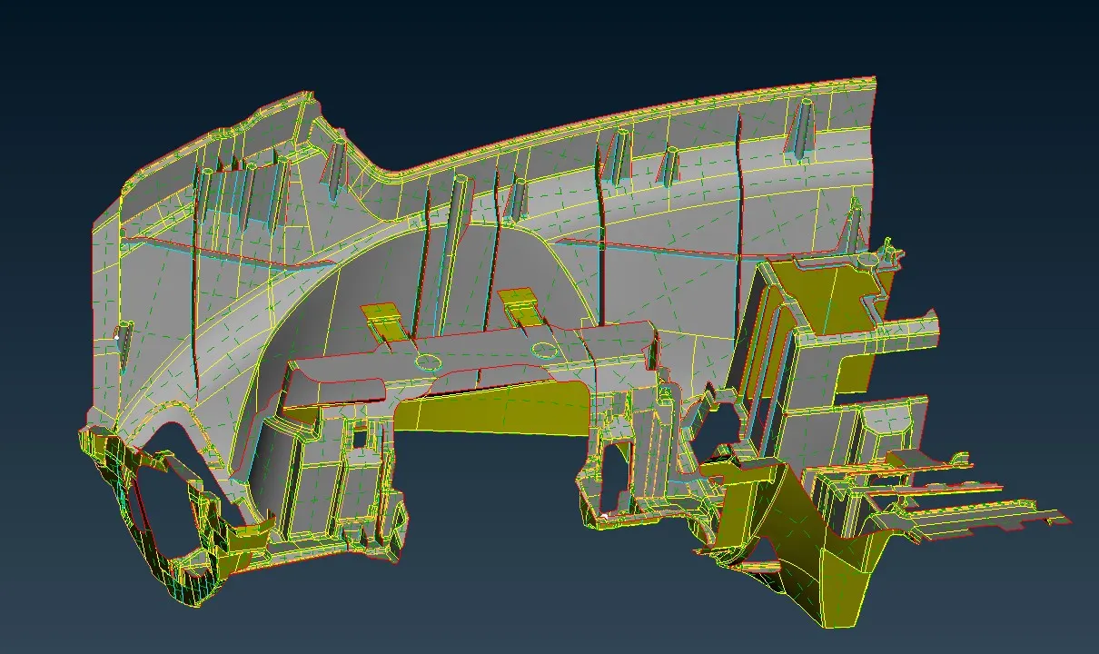
Fig 3 MIdsurface of the entire IP Model
After midsurfcing we can start with meshing.First set the quality criteria in Quality.Then we can make some cuts in geometry so that meshing algorithm can gave us the most appropriate mesh flow.This can be done using cuts in the mesh module.Then we can set the hotpoints in the model at 4 mm apart.This can be done using the length option in perimeters in mesh module.Set the length as 4 mm and select the entire midsurface and press middle click.Then we can start meshing surface by surface.
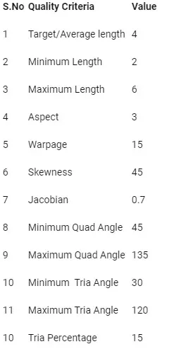
Fig 4 Quality Criteria need to follow while meshing
The algorithm BEST in MESH GENERATION TAB.And incase we are not satisfied by the mesh we can always make use of the RECONSTRUCT option in shell mesh tab.And after the reconstruction we can make use of smoothing option to smooth the mesh flow.Since the model is having intersection surfaces very near to each other at some places we cannot always make sure the quality of elements are passing at those regions. And while smoothing always make sure the elements are alligned with the geometric boundary because while we do smoothing, the elements try to extend out of boundary to acheive good mesh because of the algorithm.In any case such deviation happens we can use Grids>Allign option to revert the nodes back to the boundary.After the meshing gets completed we need to create the properties with the required thickness and we need to apply the correct property to the correct surfaces.And we can use the MVFREE option to moves nodes to get pass the failed elements for quality.
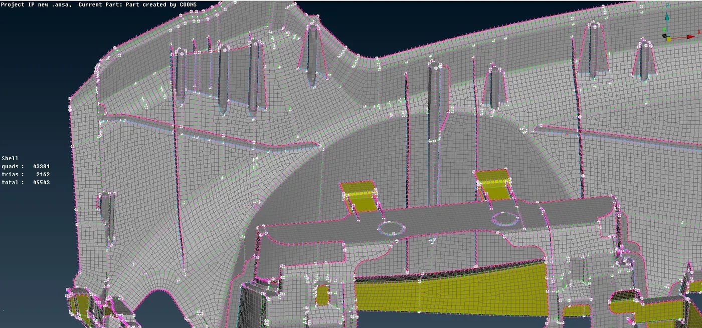
Fig 5 IP model after 2D meshing in shadow Mode
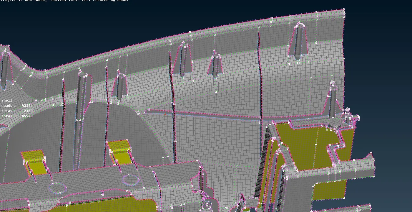
Fig 6 IP model after 2D meshing in shadow Mode
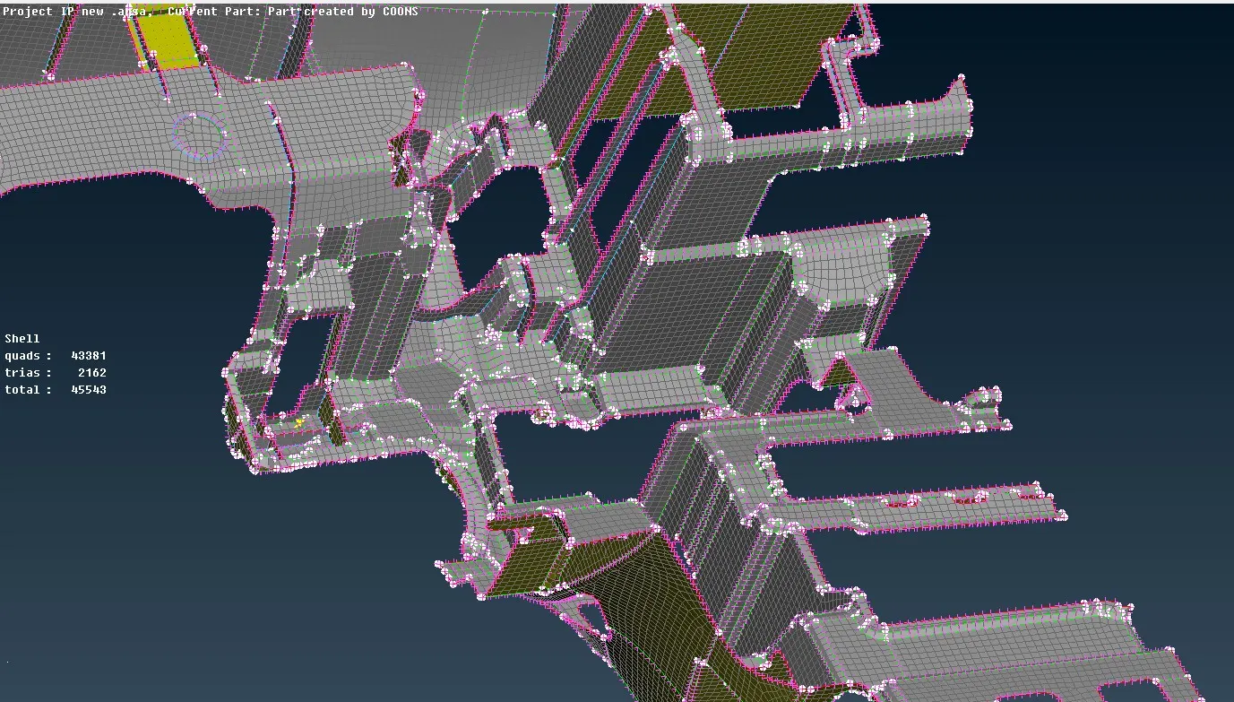
Fig 7 IP model after 2D meshing in shadow Mode
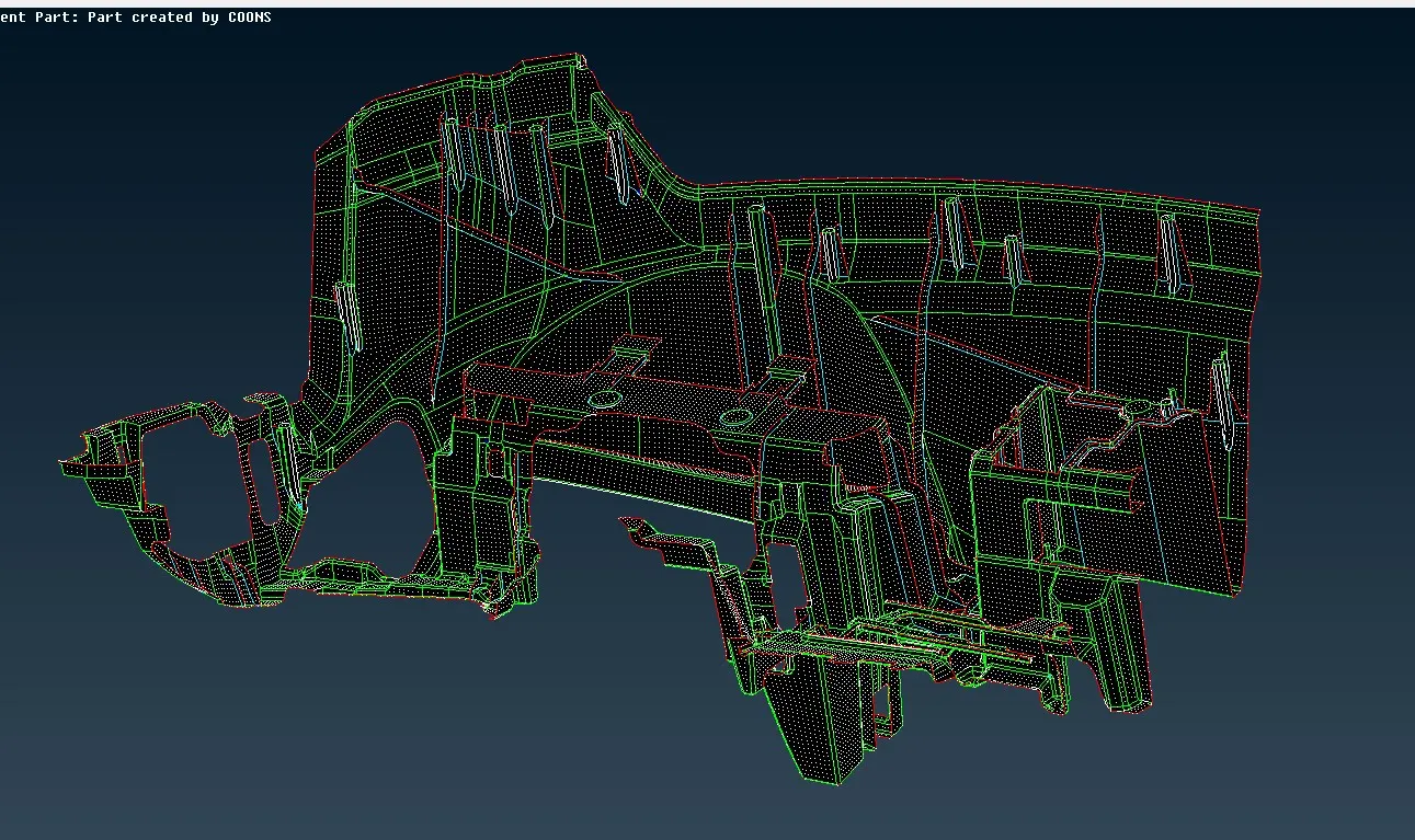
Fig 8 IP Model 2D meshed in Hidden View Mode
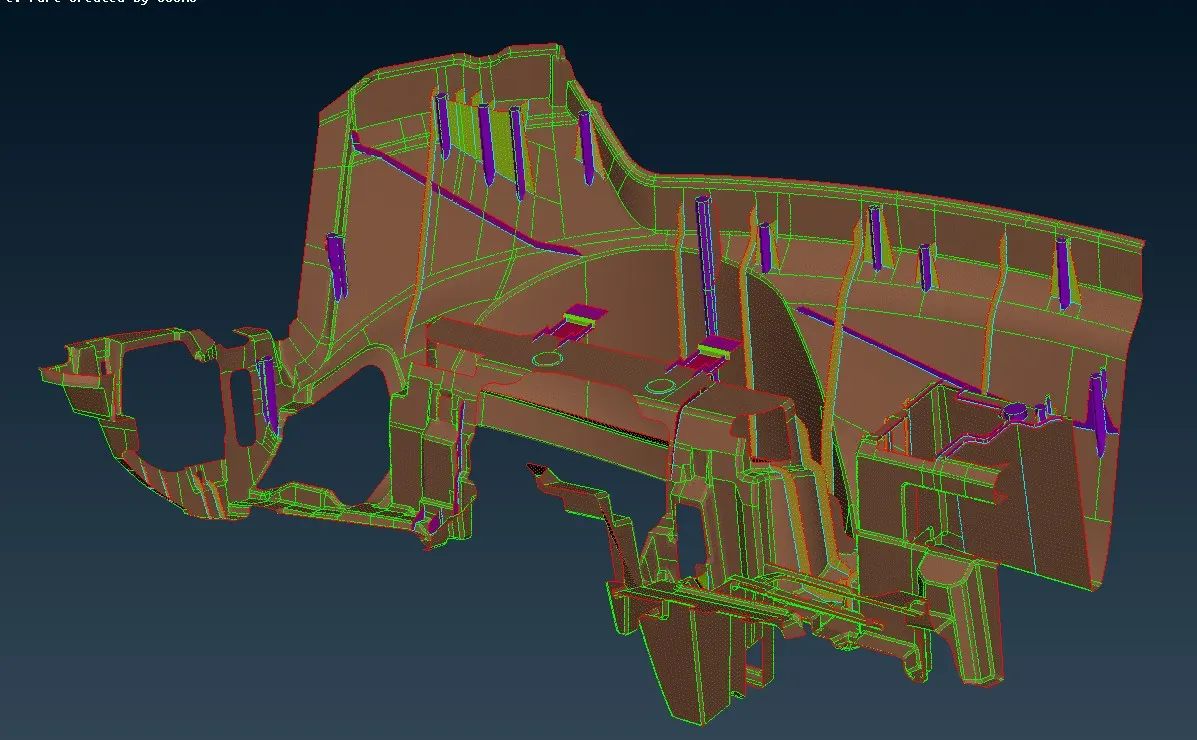
Fig 9 IP Model After 2D Meshed in Property ID View mode
RESULTS
The complete 2D meshing of Ip is done and respective thickness are applied at the respective parts by assigning proper properties to the meshed faces .
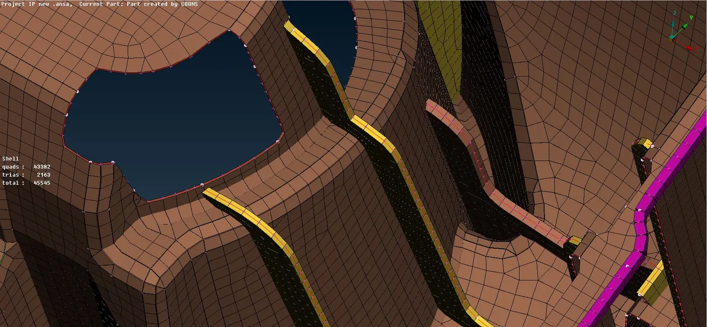
Fig 10 Property ID view after thickness application
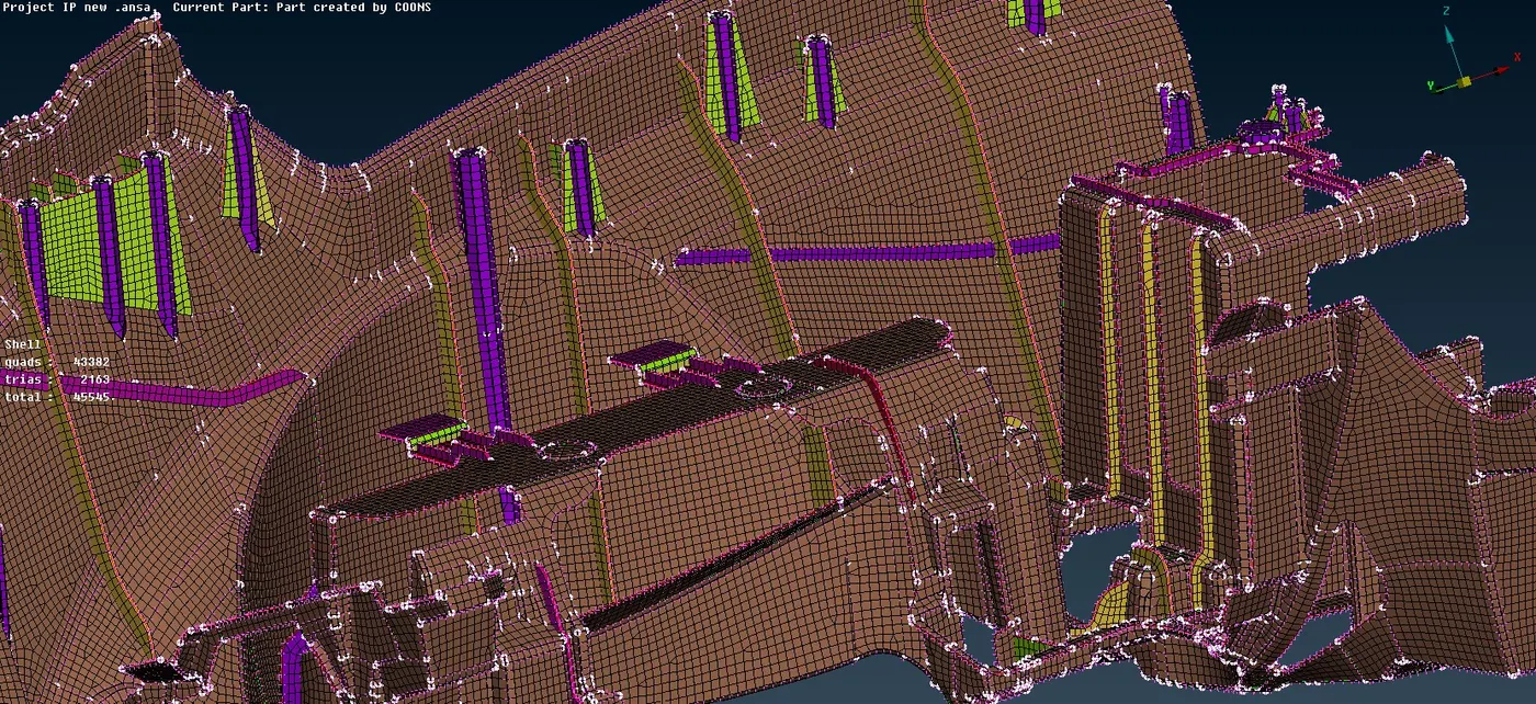
Fig 11 Complete 2D mesh of IP after switching ON Draw shell as solid option
CONCLUSION
Since the IP is a complex and big part in the automotive system the meshing of the component takes little more time.At the same time we cannot get every element pass the quality criteria ,because since it is a plastic component,for reinforcing strength there will be a lot ribs like feature present in the model.So that causes the elements to fail at some places where the feature line comes close to each other and mostly cyan cons comes adjacent in some places and in that regions we can only compromise for quality because the cyan lines cannot be reconstructed as it will distort the feature assosiated with it.So we should compromise for some OFF elements for capturing the exact feature in the model.
Link for the files
https://drive.google.com/file/d/1O-876q5gxZfhvWc0ceV0yGCAWXJlSnvh/view?usp=sharing