Project 1
WIRING HARNESS OF V16 ENGINE ASSY
AIM: Route the Wiring Harness on Given Engine and Prepare flatten view drawing in CATIA V5
OBJECTIVES:
PACKAGING RULES AND ASSUMPTIONS:
- Provide Enough Clearance to the wiring harness with respect to the surrounding
- Avoid harness routing and clipping in blind zone
- Provide additional slack to the harness according to the surrounding. 5-10% of slack
- Branch length should maintain with 50mm
- Minimum distance between clip and nearest branching point should be 25mm
- Minimum distance two breakouts should 50mm
WORKING PROCEDURES:
STEP 1:
- Download V16 Engine, Connectors, Clips & Clamps from given website
- I am using this Project deutsch connectors so connectors are downloaded from TE connectivity site
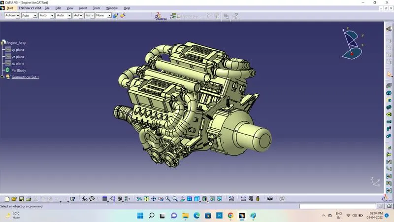
STEP 2:
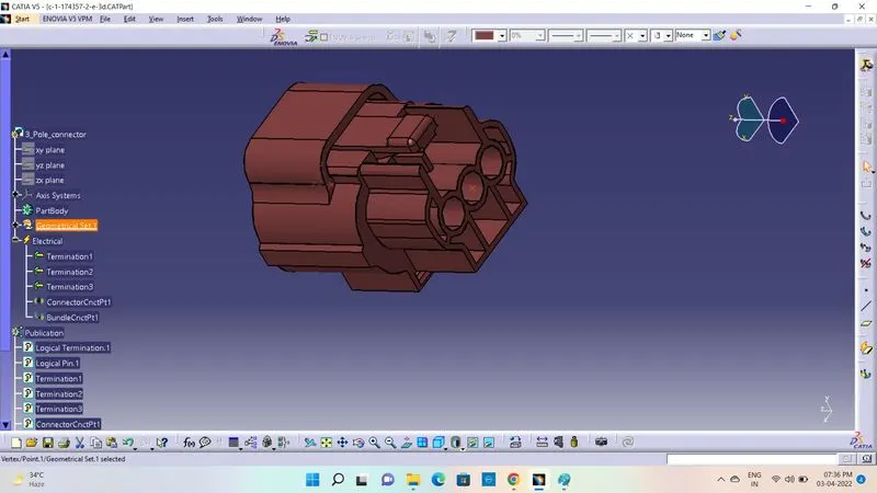
- Define 3 pole connector by using Geometrical Sets & Axis System
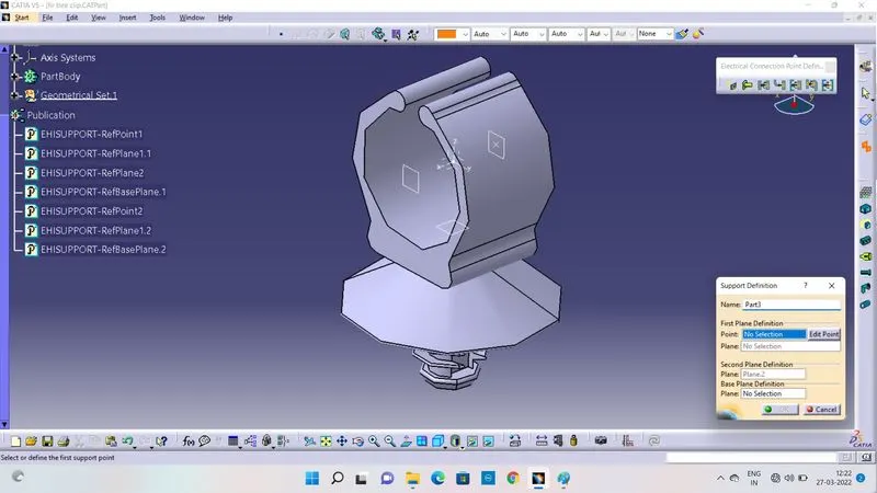
2)Define FIR Tree Clip by using Support Part Command. Support part used Clips & Clamps
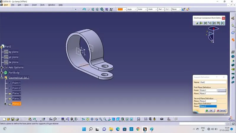
3)Define P-Clamp by using Support Part Definition
4)To Assemble and Create new Product file or (Connector Connection Point) for C-776438-4.1 Connector and C-1924487-2.1 Clip, because easy to represent in Wiring Harness Assy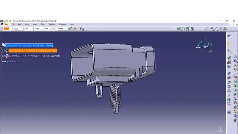
5) Convert Connector Connection Point Product file to CATpart File for defining the Inter Connection poin with clip
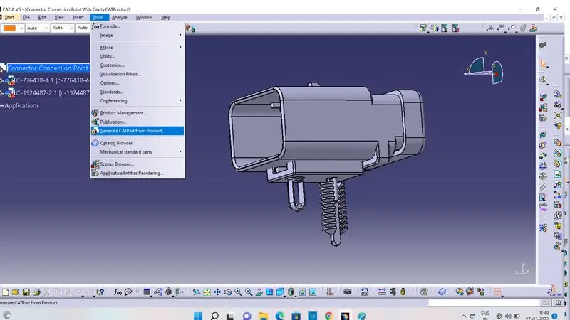
6)Defining Converted Inter Connection Point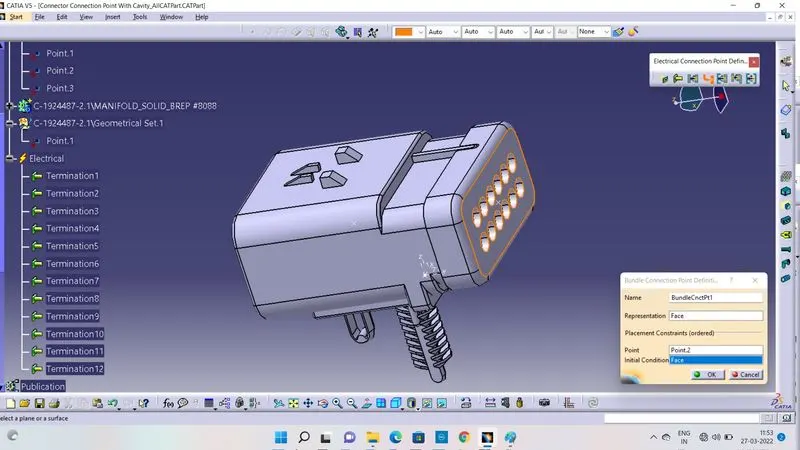
7)Defining Electrical Routing Channel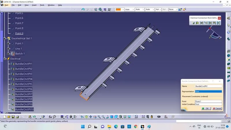
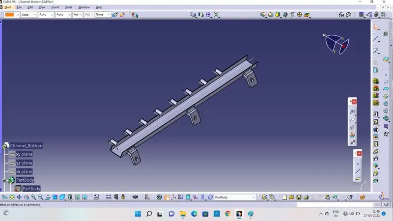
8) Defining 2 pole Connector
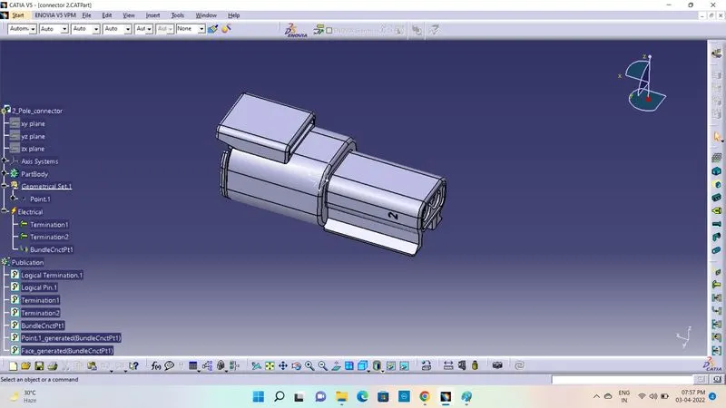
STEP 3:
- After Definition of all connectors to create new product file. i.e) Engine Harness Assembly
- After Created Engine Harness Assembly and next placed all the connectors for required area by using Move Command bars like Manipulation, Snap, Smart Move etc.,

STEP 4:
- After finishing the place of connectors. To Convert or Create Geometrical Bundle by Using Geometrical Budle Command
- After Converted Electrical Definition and Publications are added
- First to create bundle segment to Inter Connection Point to P-clamp by using Multibranchable Command
- Give Diameter for given bundle segment
- Provide Bend ratio is 1.5 times greater than bend diameter or a length
- To click Route Defenition and to select Inter Connector and P-Clamp,Click Ok the Route's are Created that represents Green in Colour
- If Green and red Colour's are showned there is some errors in bundle segment, add some slack or changed bend ratio to make avoid error's
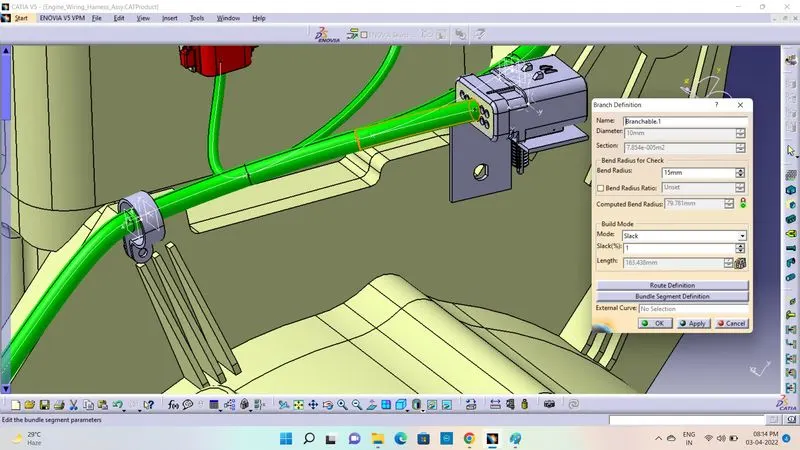
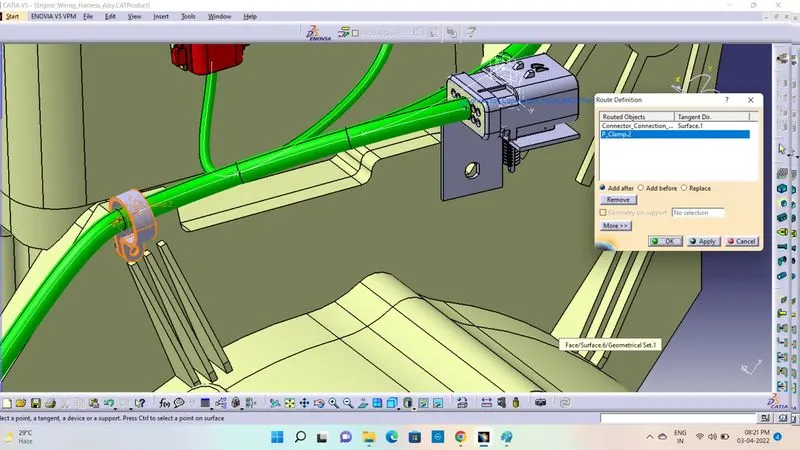
Above Same Procedures are Followed by all the Connectors Wire Routings
STEP 5: ENGINE WIRING HARNESS ASSEMBLY
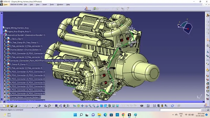
GEOMETRICAL BUNDLE ASSY
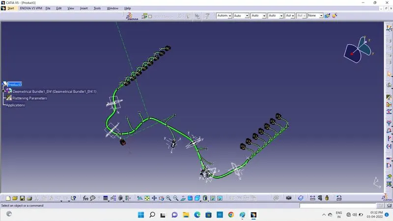
STEP 6:
- After Completed Wire Routing Converted to Flattening for Create Drawing process
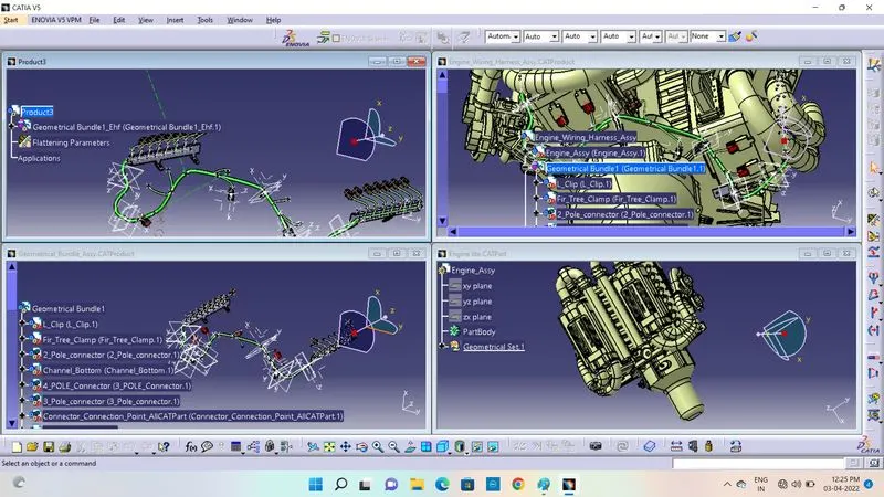 E
E
Extracting Geometrical Bundle Assembly into Flattening Assy
- After Extracting Switch Flattening Workbench to set a parameters for flattening
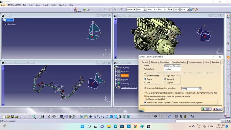
- After Extraction the bundle are flattened by using flatten command
- And also edit the all branches by using roll, bend, straighten command etc.,
STEP 7:
- By Finishing the Flattening to create the drawing for finished flattening file
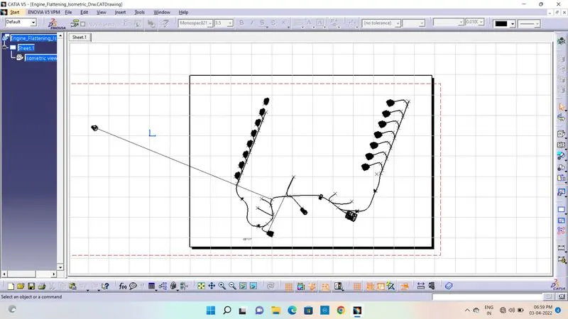
Conclusion:
- Route the Wiring Harness on Given Engine and Prepare flatten view drawing in CATIA V5 are Completed
- After Wire Routing Proto Completed this model is verified by electrical engineers. If it is Ok continue and proceed for Manufacturing