IP SUBSTRATE
AIM:To get a proper midsurfacing along with the proper 2D mesh flow on the given model at given quality criterion.
THEORY:Transparent Network Substrate (TNS), a proprietary oracle computer networking technology, supports homogeneous connectivity on top of other networking technologies such as TCP/IP, SDP and named pipes TNS operates mainly for connection to oracle databases
The Internet protocol suite provides end to end data communication specifying how data should be packetized, addressed, transmitted, routed and received. This functionality is organized into four abstraction layer which classify all related protocols according to the scope of networking involved. From lowest to highest, the layers are the link layer containing communication methods for data that remains within a single network segment (link); the internet layer providing internet working between independent networks, the transport layer handling host-to-host communication; and the application layer, providing process-to-process data exchange for applications.
PROCEDURE:Firstly make the box and perform topo on the given model and changes the perimeter length of whole the model from 20mm to 1mm which precises the model makes finer.Then needs to clear all geometric errors,errors could be NEEDLE faces can directly be removed by delete available on faces option in TOPO mode,CRACK BETWEEN THE SURFACES error could be eradicated by either perform topo or manual mid or may be deleting unnecessary hot points creating new surfaces on to it by deleting existing distorted surfaces,TRIPLE CONS are being removed by releasing the cons and topo to it again which stitched the cons ,UNCHECKED FACES errors are being directly removed by deleting it and creating a new faces over there this makes the geometric errors perfectly be cleaned.
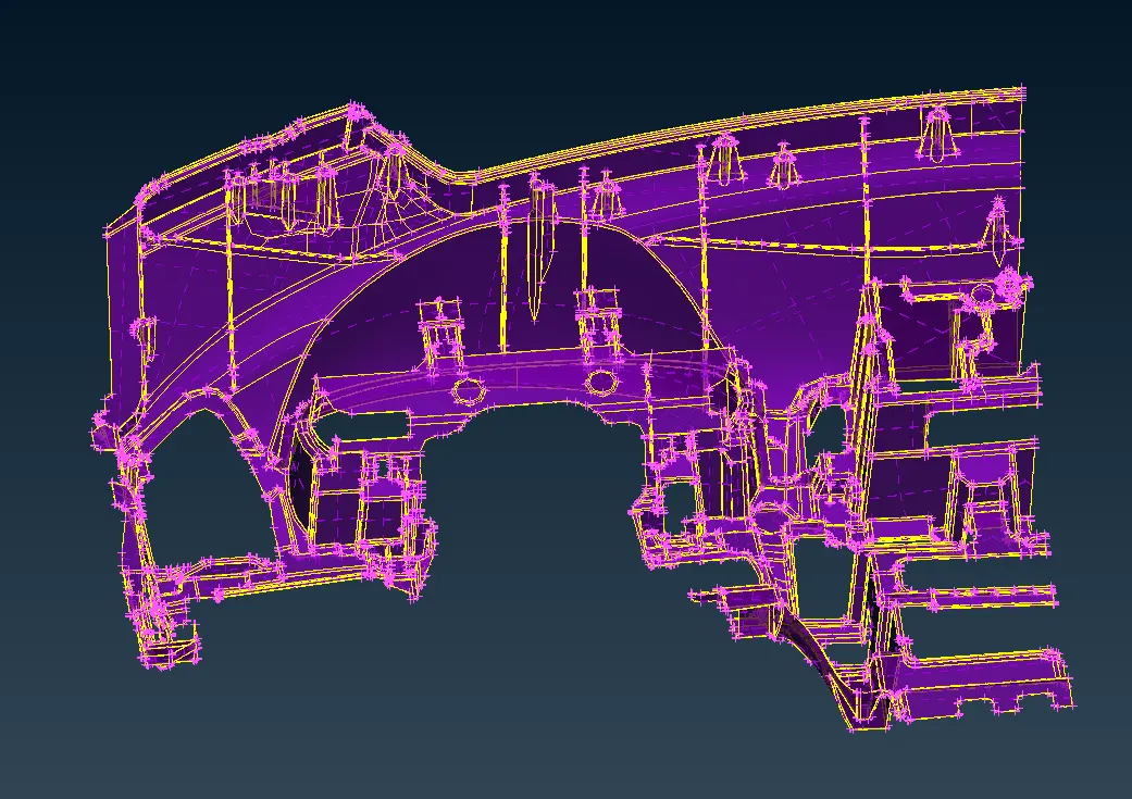
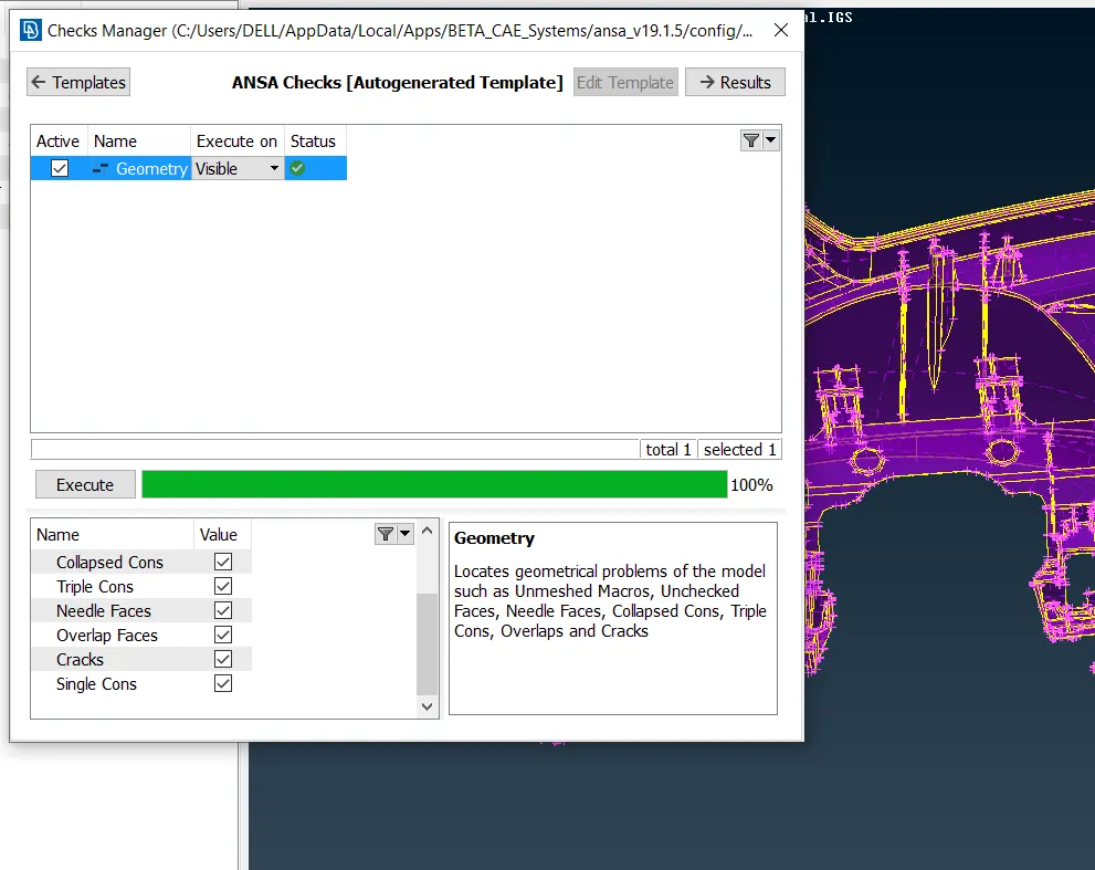
After execution of such procedure we gotta go for midsurfacing having varying thickness using offset ,middle and curve middle
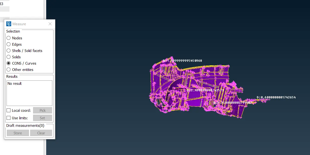
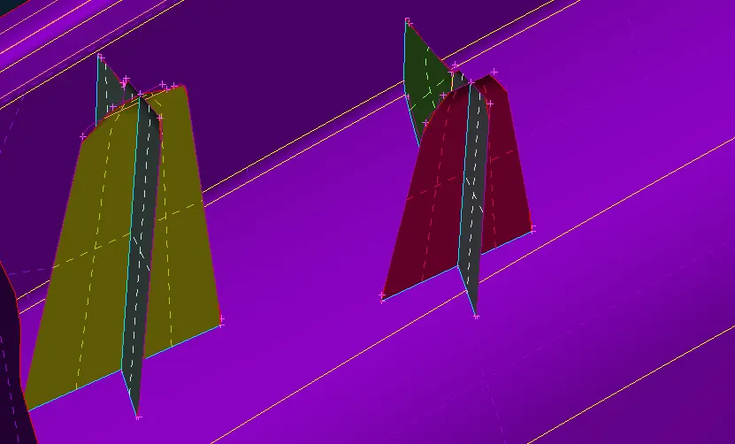
The upper image shown the varying thicknesses of the model where either offset or middle will work in order to extract the mid surfaces and the rest of the areas where this option wouldn't work we have to go for CURVE MIDDLE like the section called dog house having cylinder shaped attached ribs,since cynliner is not considered under 2D mesh so in order to extract the surface we are going to take cross like surfaces which will show in the below images.
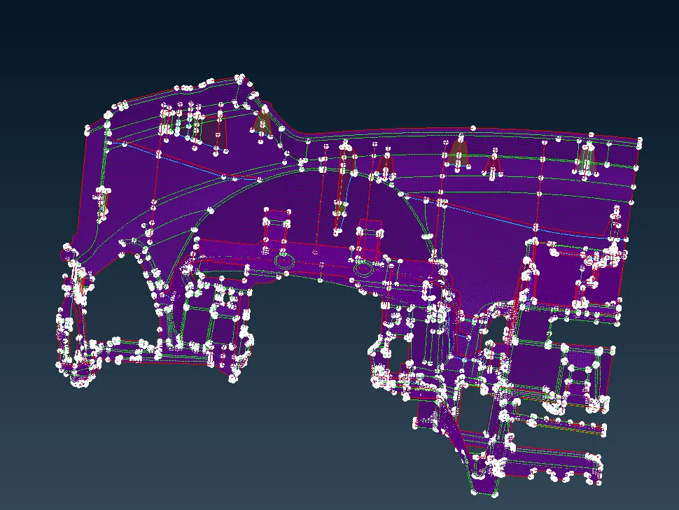
Instrument panel should be isolated and taking a mid surfacing of it too separately having various thicknesses.Doing such procedure midsurfacing gets completed and the mid plane that we have got from the CAD MODEL is shown below:
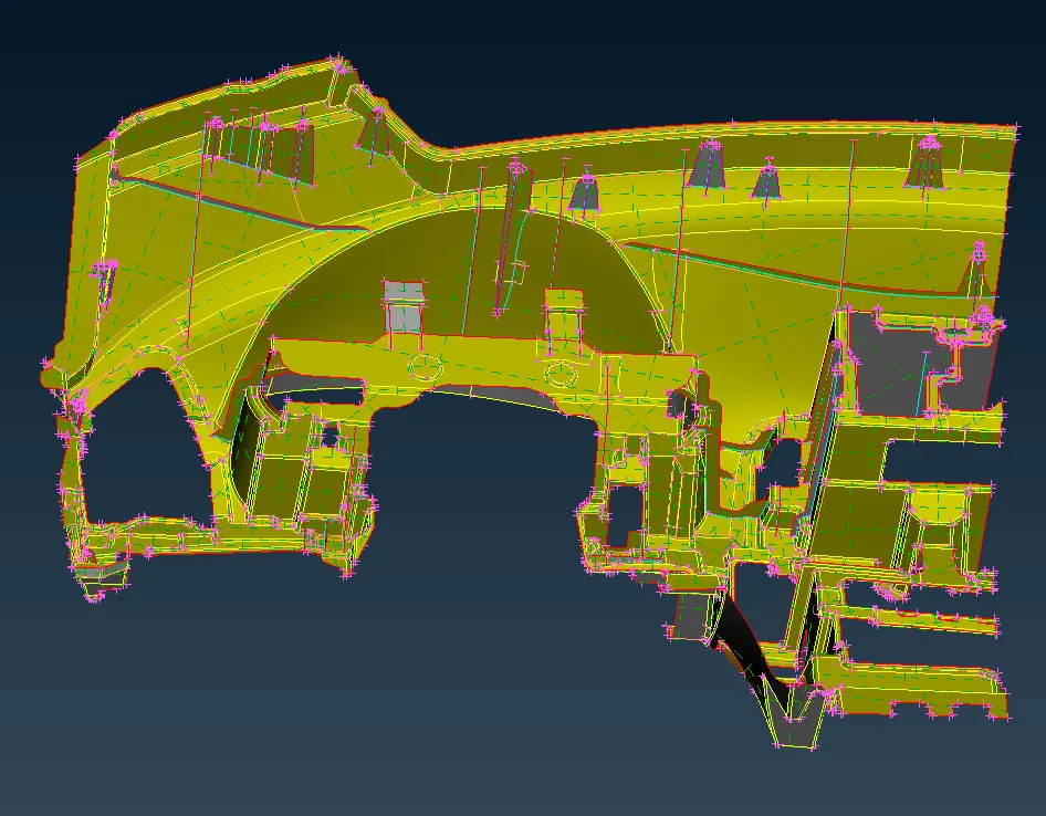
Here also in mid surface we have to precise the model from 20mm to 4mm to make it more finer and geometric error should be cleaned here as well except single cons and triple cons,errors could be collapsed cons,unchecked faces and cracks between the surfaces.
Now moving on to the meshing part,quality criterion are as follows:
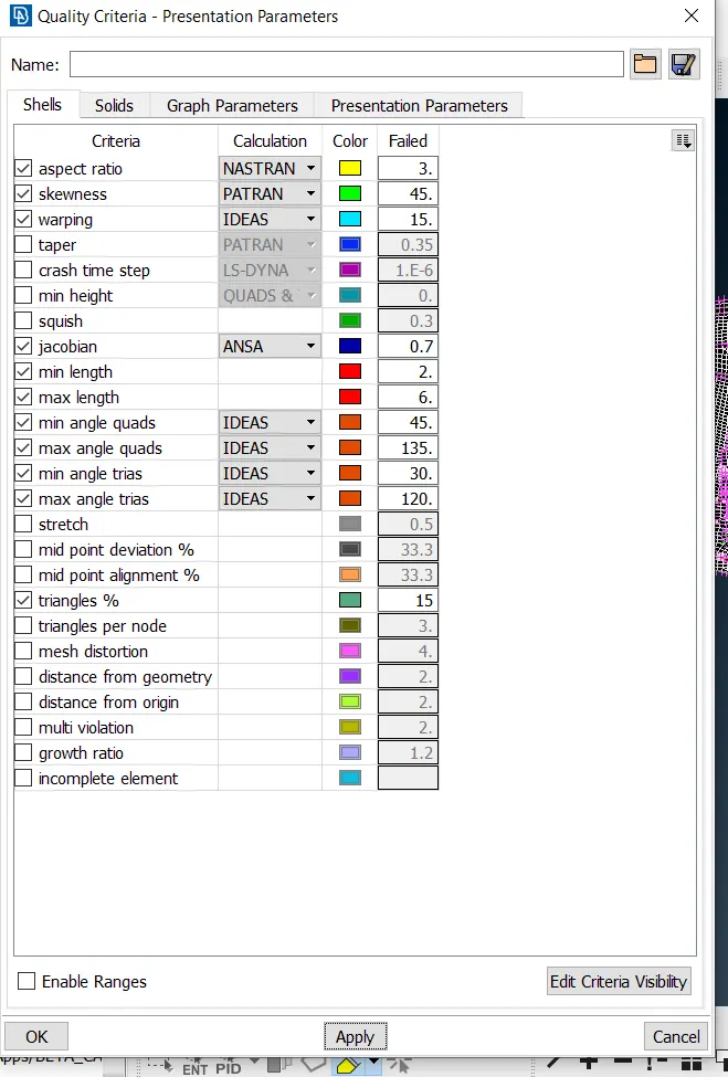
Taking it into consideration we give spot mesh in a particular region one by one and reconstruct it one by one parallelarly and smooth option are also been taken in order to make mesh flow with proper with quads elements and less trias elements with no rotating quads.
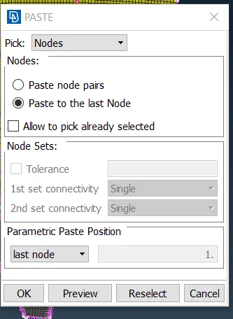
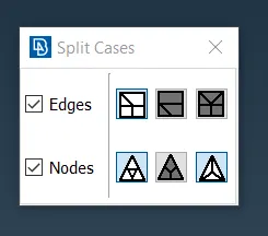
Wherever it seems the opposite trias we paste them using paste option in grids in mesh mode and wherever trias are pointing each other gotta go with split option in order to make it quads.
Now we have to do a lot of defeaturing in order to remove the off elements this is due to failing for quality criterion and all the other options are worthiless to use.It is a process to make cut and delete the particular area which is failing for or removing those cuts which obstruct the proper mesh flow or which are creating off elements.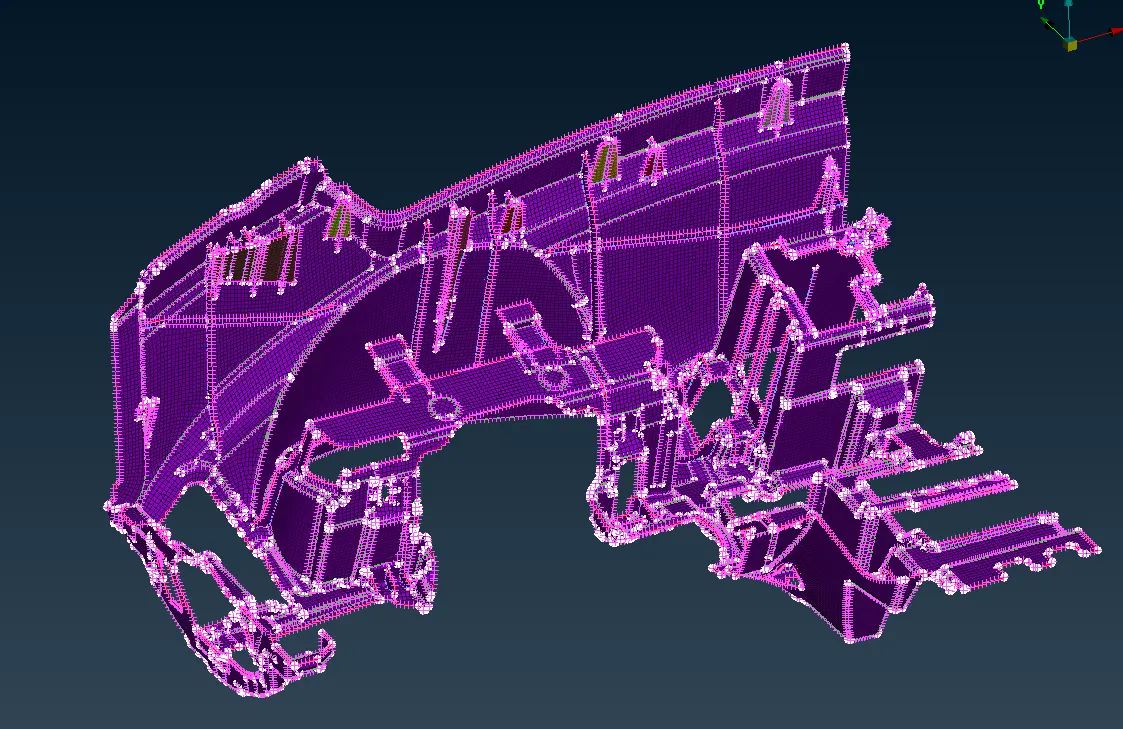
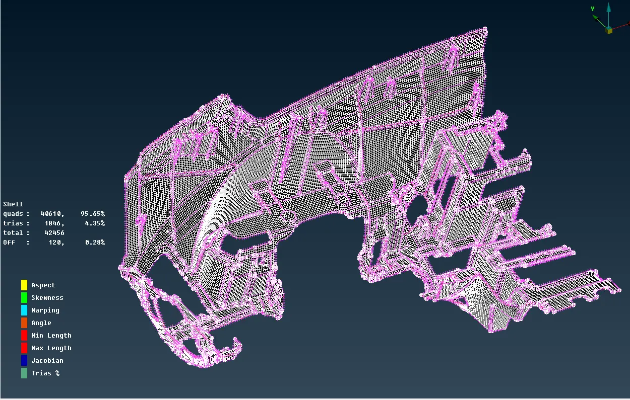
These are techniques results in proper mesh flow with less trias and very less off elements in hidden mode we can obsereve the outcomes in percentages
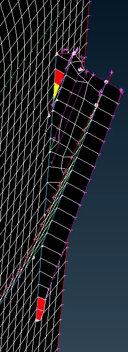
Now the region where someone bounds to have off elements may be the convergence section where two surfaces are stitching or triple cons are close to each other or else intersecting with another like shown below:
Finally the mid plane can be seen with CAD model opening with shell as solid:
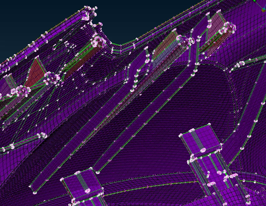
Now using elements release in mesh mode leads to FE part gets detached from CAD geometry.
CONCLUSION:(a)Got to know to take midsurfacing of various thicknesses using various techniques.
(b)Also got an experience to do a proper meshing using various options as well also knew about the releasing of FE model from CAD.