Project 1
1)
Boost DCM :
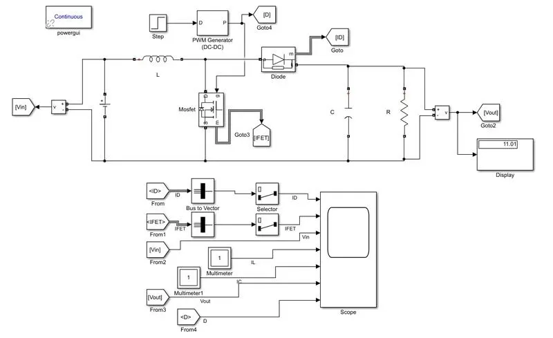
The purpose of the de-de boost converter circuit is to draw power from the de voltage source, and supply power to the load at a higher de voltage value.
This task is accomplished by first closing the switch to store energy in the inductor, and then opening the switch to transfer that energy to the capacitor, where it is available to the load.
The discontinuous conduction mode (DCM) occurs when the converter is at light load (low current).
Calculations:
Vin = 5V
Vo = 12
P = 150W
Vin/Vo = 1/1-D
D = 0.75
Vo = D1*Vin / D1-D
12/5 = D1/D1-0.75
D1 = 1.29
Po = Vo^2/R
R = Vo^2/Po
R = 12^2/150
R = 0.96ohm
Po = Pin
Po = Vin * IL
IL = 5/150
IL = 30A
IL = 1/2*delIl*D1
delIL = 2*IL/D1
delIL = 2*30/1.29
delIL = 60.06A
L = D*Vin/fdelIL
L = 0.75*5/25000*60
L = 1.9423uH
C = DT/2R
C = 0.75/2*0.96*25000
C = 0.242uF
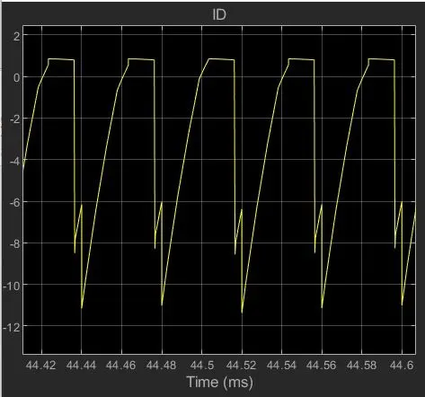
Id = 1/2*delIL*(D1-D)
Id = 16.362A
Matlab simulation:
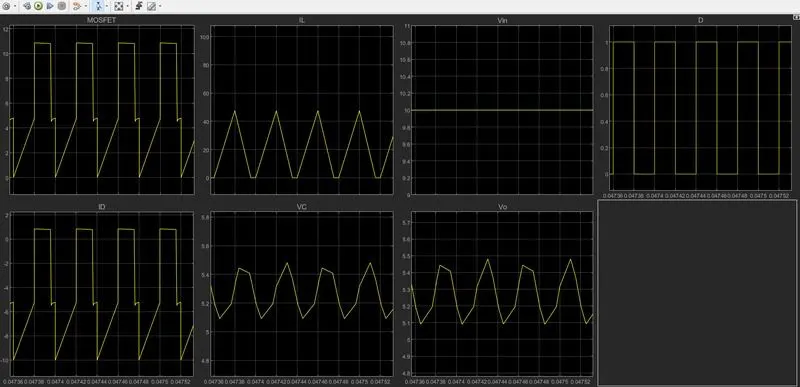
Output waveform:
Diod Current:
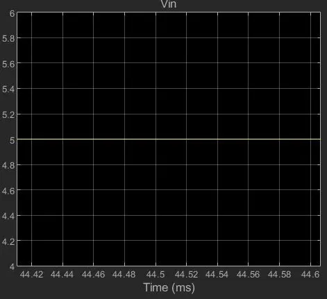
Input Voltage:
Vin = 5V
Capacitor Current:
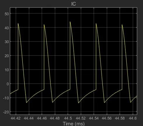
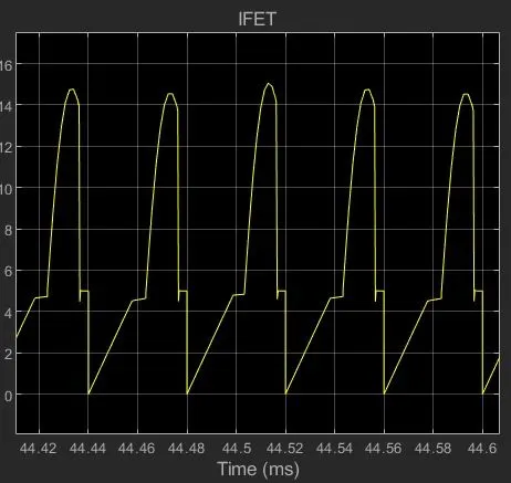
Mosfet Current:
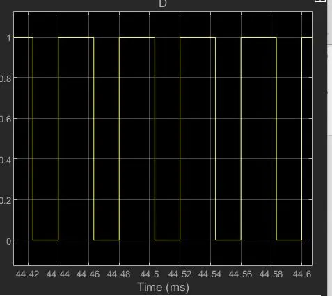
Duty Ratio:
Inductor current:
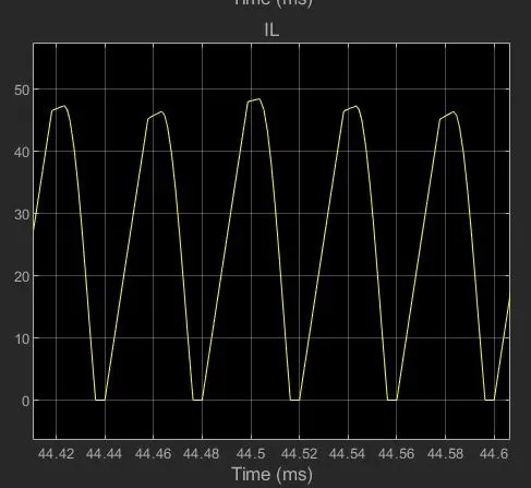
DCM operation the inductor current rises in the first interval when the switch is turned on, reaches a peak right before the switch is to be turned off, and resets to zero at the end of the second interval and remain zero until next switching occur.
Output Voltage:
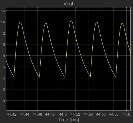
The key principle that drives the boost converter is the tendency of an inductor to resist changes in current by either increasing or decreasing the energy stored in the inductor magnetic field. In a boost converter, the output voltage is always higher than the input voltage.
2)
Buck Converter DCM:
Vin = 10V
Vo = 5V
P = 100W
Vin/Vo = D
D = 5/10
D = 0.5
D1 = D*Vin/Vo
D1 = 0.5*10/5
D1 = 1
Po = Vo^2/R
R = Vo^2/Po
R = 5^2/100
R = 0.25ohm
Po = Pin
Po = Vin*Iin
Iin = Po/Vin
Iin = 100/10
Iin = 10A
Iin = 1/2*delIiN*D
deIL = 50A
L = (Vin-Vo)*DT/delI
L = 2uH
Id = 1/2*deLI*(D1-D)
Id = 12.5
delV = delIL/8f
delV = 1/4000V
C = T*delI/8delV
C = 625uF
Matlab simulation:
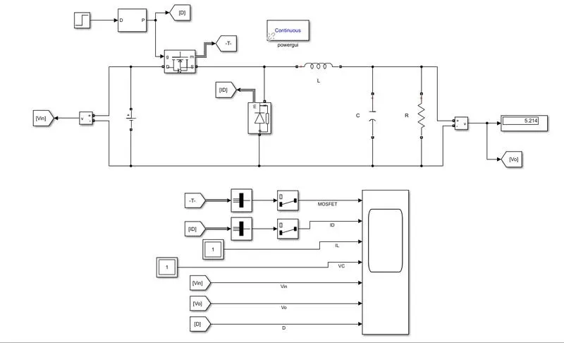
Output waveform:
Mosfet Current:
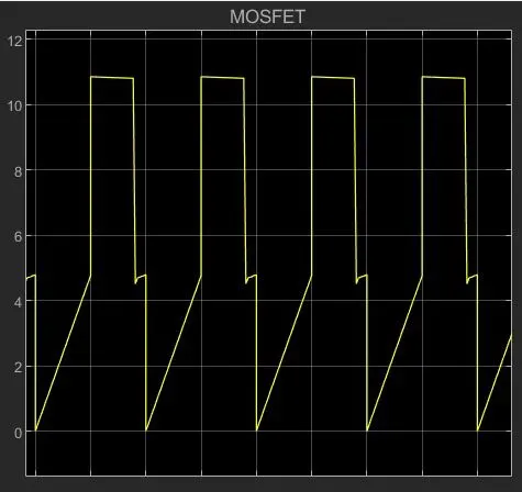
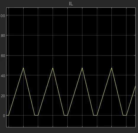
Inductor Current:
DelIL = 50A
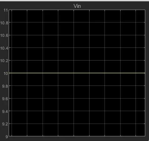
Input Voltage:
Vin = 5V
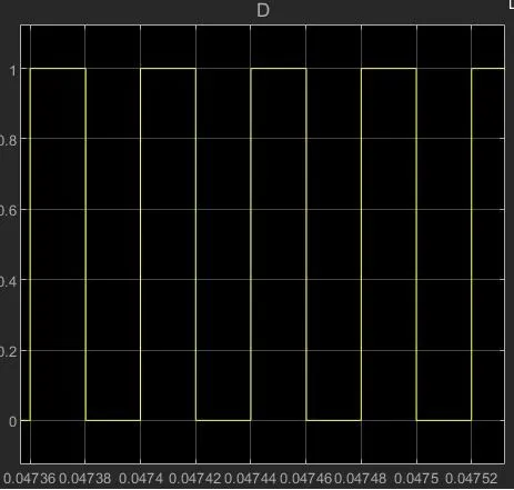
Duty ratio:
D = 0.5
D1 = 1
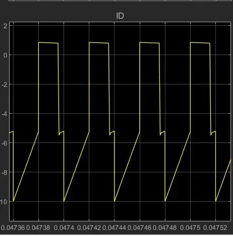
Diod current:
Id = 12.5A
Capacitor Voltage:
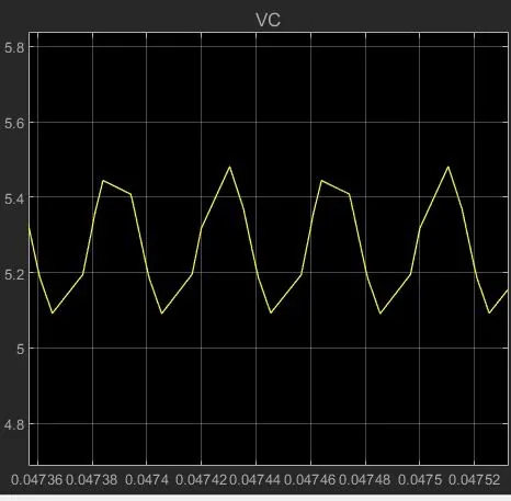
Main disadvantage is Increased output capacitance.
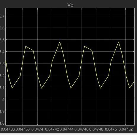
Voltage Output:
3)
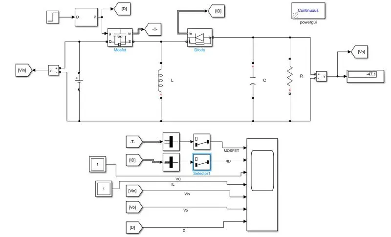
Inverting Buck-boost Converter:
A Buck-Boost converter transforms a positive DC voltage at the input to a negative DC voltage at the output. The circuit operation depends on the conduction state of the MOSFET: On-state: The current through the inductor increases and the diode is in blocking state.
working:
A Buck-Boost converter transforms a positive DC voltage at the input to a negative DC voltage at the output. The circuit operation depends on the conduction state of the MOSFET: On-state: The current through the inductor increases and the diode is in blocking state.
Calculations:
Vin = 30V
Vo = -45V
P = 300W
Vo/Vin = -D/1-D
D = 0.6
Po = V^2/R
R = V^2/Po
R = 45^2/300
R = 6.75ohm
L = R(1-D)^2/2f
L = 6.75(1-0.6)^2/2*25000
L= 0.216uH
C = D/2fR
C = 0.6/2*25000*6.75
C = 1.78uF
IL = -Io/1-D
IL = 6.67A
deLIL = DVin/fL
delIL = 33.33A
ILmax = IL+delIL
ILmax = 6.67+33.33
ILmax = 40.003A
ILmin = IL-delIL
ILmin = 6.67-33.33
ILmin = -26.66
Matlab Simulation:
Output Wave form:
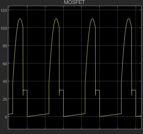
Mosfet Current:
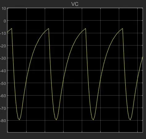
capacitor Voltage:
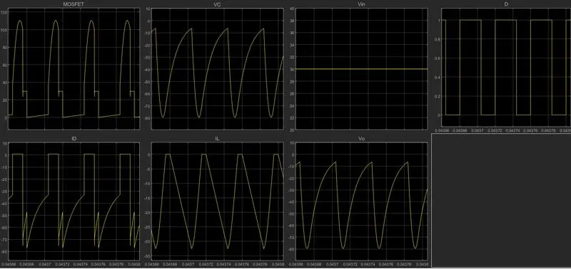
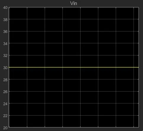
Input Voltage:
Vin = 30V
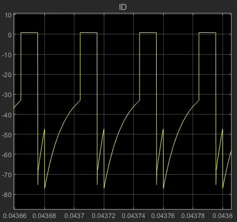
Diode Current:
Inductor Current:
Output voltage:
output voltage magnitude that is either greater than or less than the input voltage magnitude.
A Buck-Boost converter transforms a positive DC voltage at the input to a negative DC voltage at the output. Energy is transferred from the inductor to the capacitor resulting in a decreasing inductor current and a voltage across the resistor with the opposite polarity compared to Vin.