Project 1 - 2D meshing on the instrumental Panel
Aim:
2D meshing on the instrumental Panel
Objective:
For the given component, check for the geometrical errors and mesh with the given element Quality criteria. After meshing the component the thickness has to be assigned.
Write a detailed report on your meshing process and also mention which method you used to extract the mid-surface along with the reason.
|
S.No |
Quality Criteria |
Value |
|
1 |
Target/Average length |
4 |
|
2 |
Minimum Length |
2 |
|
3 |
Maximum Length |
6 |
|
4 |
Aspect |
3 |
|
5 |
Warpage |
15 |
|
6 |
Skewness |
45 |
|
7 |
Jacobian |
0.7 |
|
8 |
Minimum Quad Angle |
45 |
|
9 |
Maximum Quad Angle |
135 |
|
10 |
Minimum Tria Angle |
30 |
|
11 |
Maximum Tria Angle |
120 |
|
10 |
Tria Percentage |
15 |
Parent geometry
Import the model as step file inside the ANSA workbench
Perform topological check from the cons module
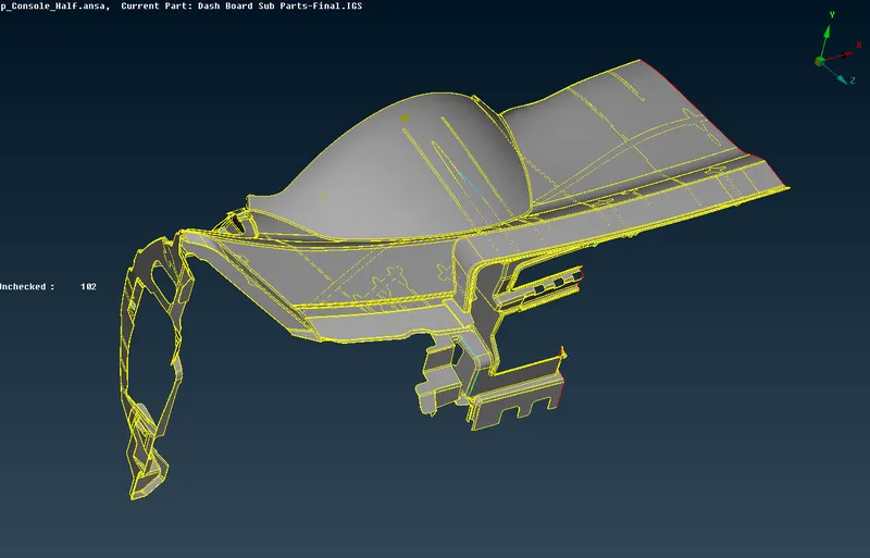
fig 1
Mid surfacing:
Extract the mid surface region with the offset command in cons tab.
Assign thickness to different regions of mid surfaces.
Set property ID to different regions.
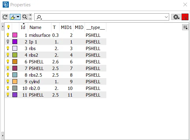
fig 2
Mid surfacing of instrument panel outer cover:
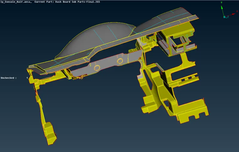
fig 3
Mid surfacing of external ribs:
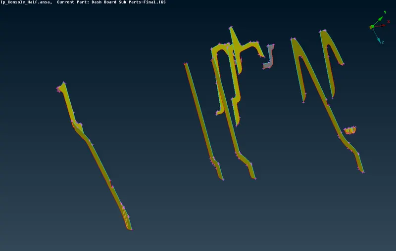
fig 4
Mid surfacing of side ribs:
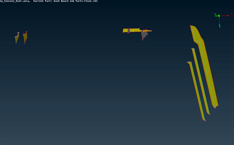
fig 5
Mid surfacing of ribs:
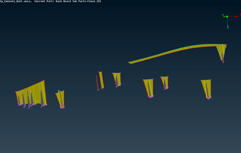
fig 6
Mid surfacing of mid ribs:
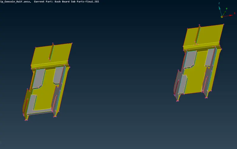
fig 7
Mid surfacing of inclined ribs:
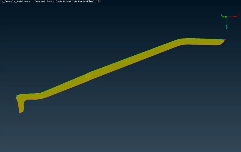
fig 8
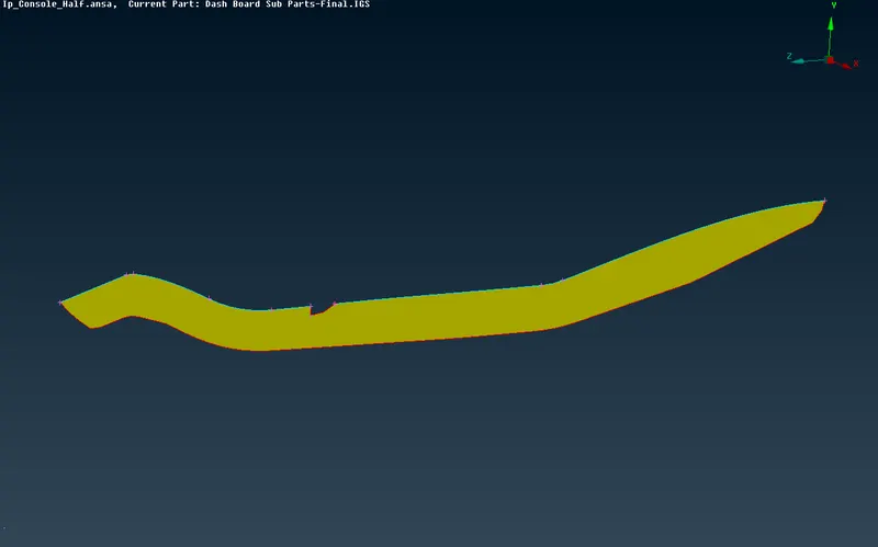
fig 9
Mid surfacing of outer ribs:
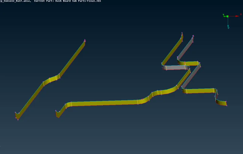
fig 10
Mid surfacing of cylindrical ribs:
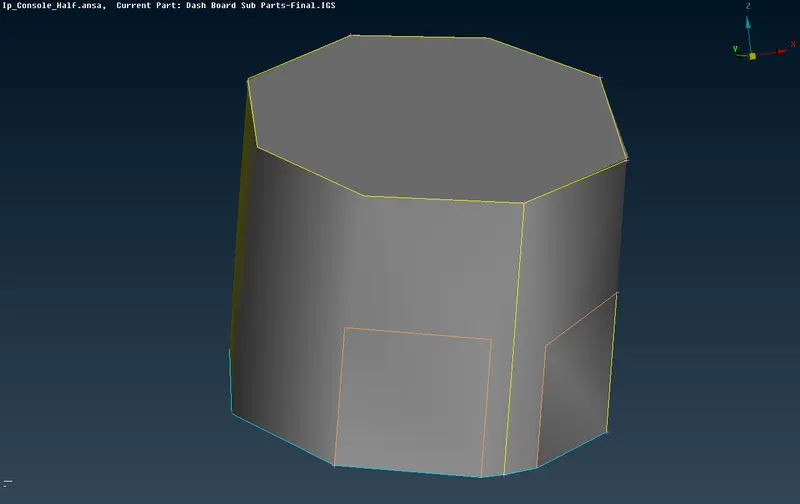
fig 11
Assembled view of mid surfacing of the entire component
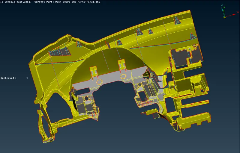
fig 12
Meshing
From the mesh module select the perimeter option
Define the length by selecting the entire perimeter or macros. Give a target length to distribute the cons evenly.
The quality checks criteria are given as
|
S.No |
Quality Criteria |
Value |
|
1 |
Target/Average length |
4 |
|
2 |
Minimum Length |
2 |
|
3 |
Maximum Length |
6 |
|
4 |
Aspect |
3 |
|
5 |
Warpage |
15 |
|
6 |
Skewness |
45 |
|
7 |
Jacobian |
0.7 |
|
8 |
Minimum Quad Angle |
45 |
|
9 |
Maximum Quad Angle |
135 |
|
10 |
Minimum Tria Angle |
30 |
|
11 |
Maximum Tria Angle |
120 |
|
10 |
Tria Percentage |
15 |
Meshing of instrument panel outer cover:
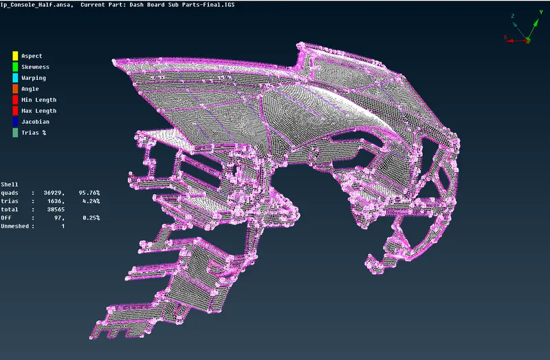
fig 13
Meshing of external ribs:
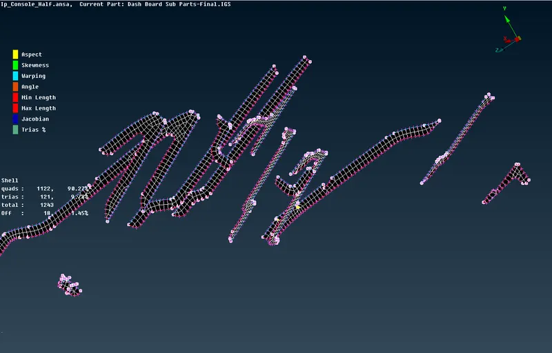
fig 14
Meshing of side ribs:
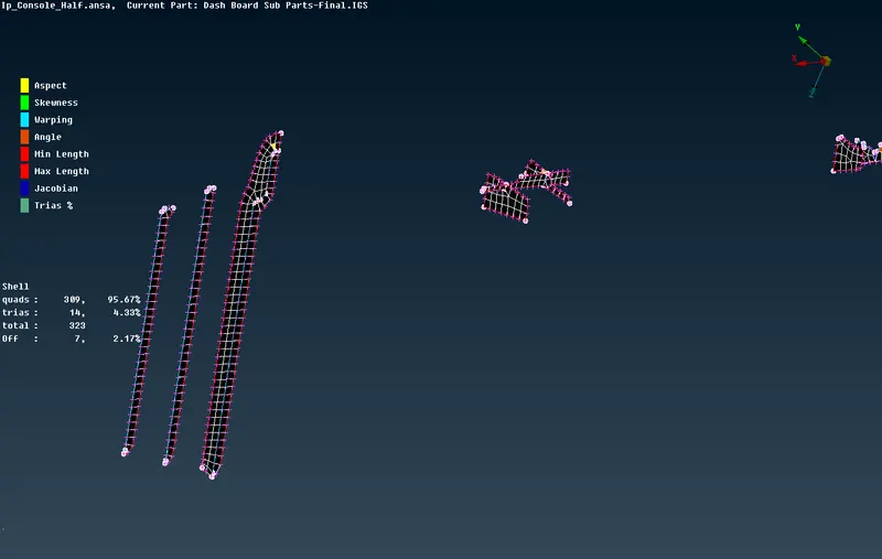
fig 15
Meshing of ribs:
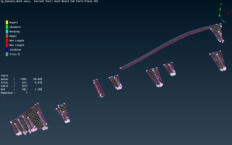
fig 16
Meshing of mid ribs:
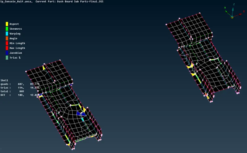
fig 17
Meshing of inclined ribs:
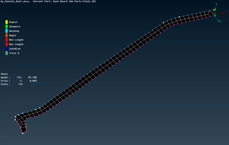
fig 18
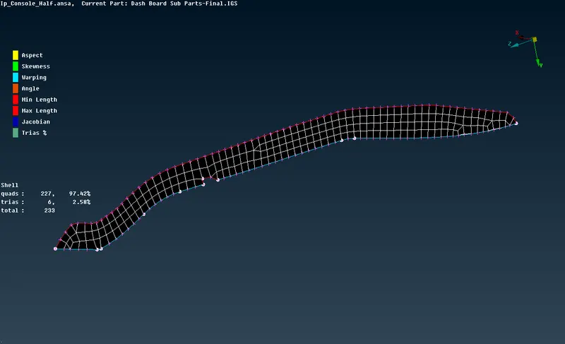
fig 19
Meshing of outer ribs:
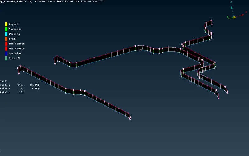
fig 20
Meshing of cylindrical ribs:
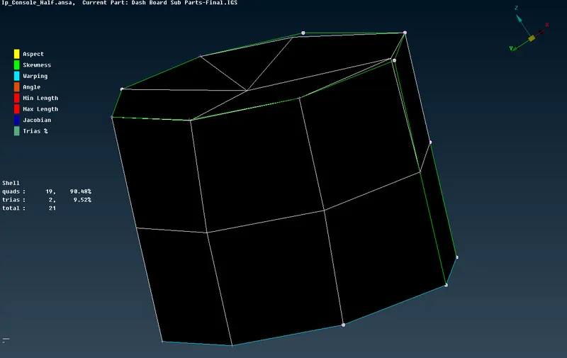
fig 21
Complete overview of meshed instrument panel
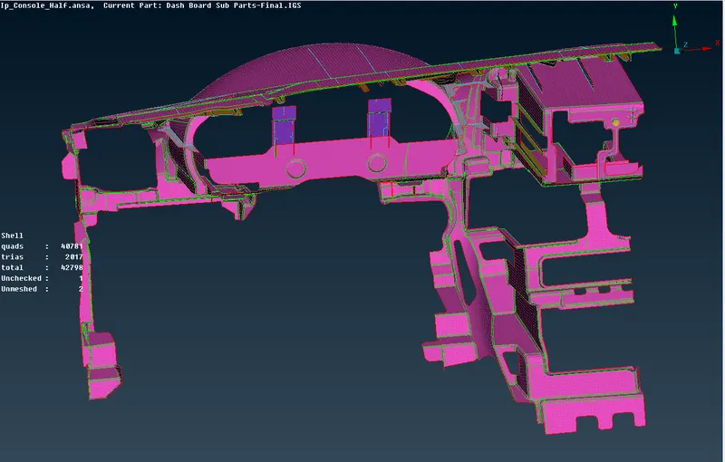
fig 22
Conclusion:
The meshing of instrument panel has been done according to the required mesh criterias.