Project 1 - 2D meshing on the instrumental Panel
Question:
For the given component, check for the geometrical errors and mesh with the given element Quality criteria. After meshing the component the thickness has to be assigned.
Write a detailed report on your meshing process and also mention which method you used to extract the mid-surface along with the reason.
|
S.No |
Quality Criteria |
Value |
|
1 |
Target/Average length |
4 |
|
2 |
Minimum Length |
2 |
|
3 |
Maximum Length |
6 |
|
4 |
Aspect |
3 |
|
5 |
Warpage |
15 |
|
6 |
Skewness |
45 |
|
7 |
Jacobian |
0.7 |
|
8 |
Minimum Quad Angle |
45 |
|
9 |
Maximum Quad Angle |
135 |
|
10 |
Minimum Tria Angle |
30 |
|
11 |
Maximum Tria Angle |
120 |
|
10 |
Tria Percentage |
15 |
Solution:
Introduction:
Align Manager:
Align manager is set of commands in ANSA which simplifies the process of 2D meshing of the component:
- We can add/define/edit shells of the micro areas to the surfaces.
- We can define the perimeters of the micro areas to the faces.
- We can imprint the edges of the features.
Now let's look into the procedure of 2D meshing of the intrument panel:
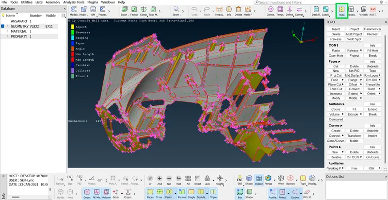
Fig1.1: Intrument panel in hand for the 2D meshing.
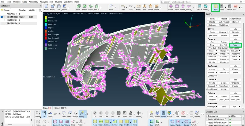
Fig1.2: Executing 'Topo' command for joining the available surfaces.
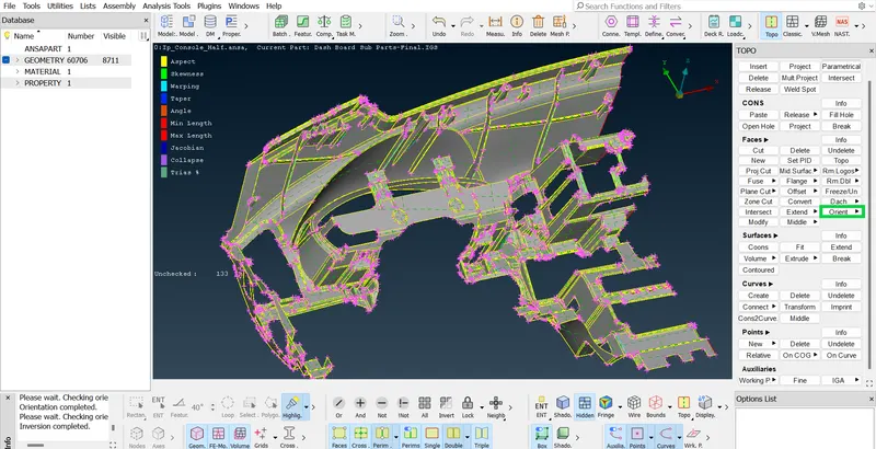
Fig1.3: Executing the 'Orientation' command.
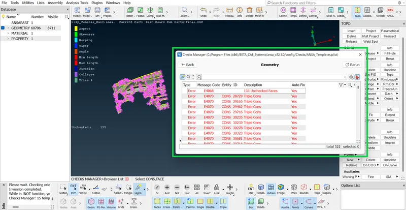
Fig1.4: Executing the 'Geometrical checks' and fixing them.
Fix the errors except 'Triple cons' errors, because the geometry itself consists of the features for which triple cons are must.
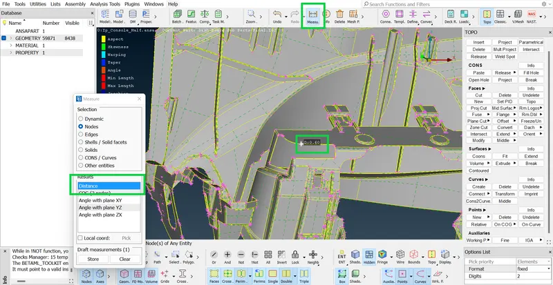
Fig1.5: Executing the measurement operation to identify the minimum available thickness of the component.
In order to perform the 'Casting' operation we must know the minimum available thickness of the component, therefore we are measuring the different features of the geometry to determine the minimum available thickness of the geometry.
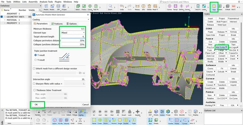
Fig1.6: Executing the 'Casting' midsurface mesh generation command.
'Casting' approach is followed in order to extract the 2D mesh for the given component because of the complexity of the model. Manual extraction of the midsurface is very difficult and time consuming process. Also creating 2D mesh for the midsurface skin is also a time consuming approach.
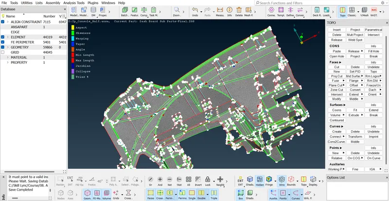
Fig1.7: 2D mesh available after executing the 'Casting' operation.
Elements of the 2D mesh of the component available after the 'Casting' will fails for features and at some base surfaces. This can be repaired by using the basic operations in the tool bar such as Join cons, Cut cons, Insert hot points, Delete hot points, Cons2curve, Middle, Reconstruct and using the Align manager.
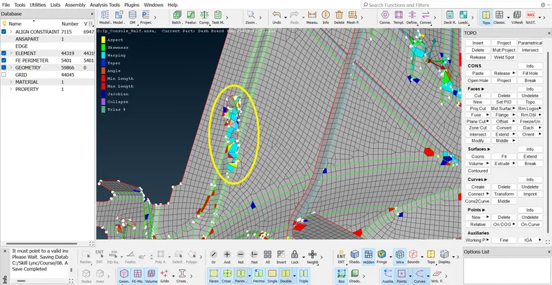
Fig1.8: Shells failing for dog house feature.
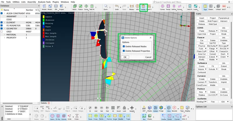
Fig1.9: Deleting failed shell elements in order to recreate them.
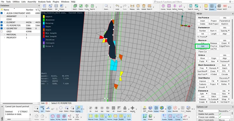
Fig1.10: Executing the 'Join' command to eliminate the unnecessary joints.
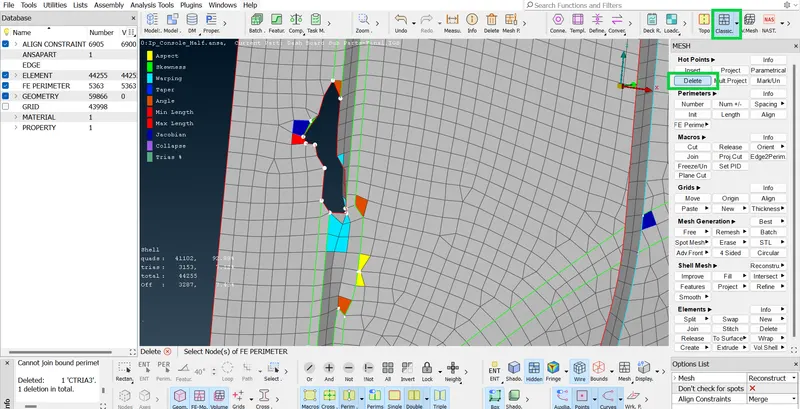
Fig1.11: Deleting the unnecessary hot points.
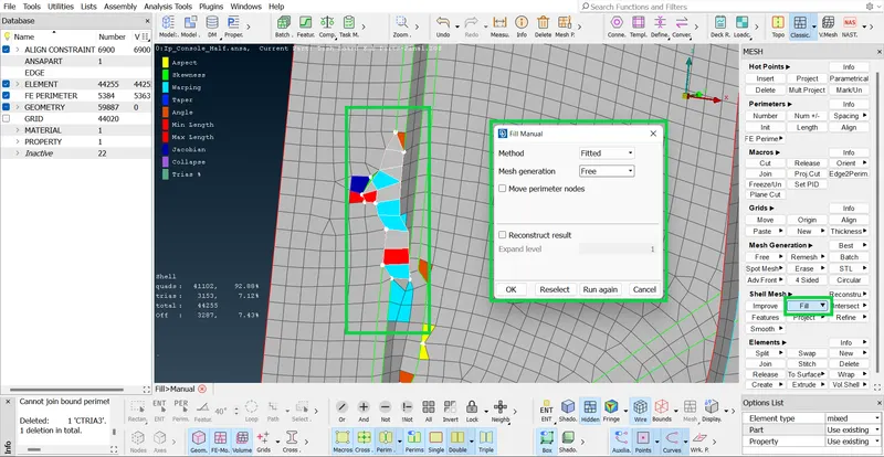
Fig1.12: Creating the new shell elements by executing the 'Fill' command.
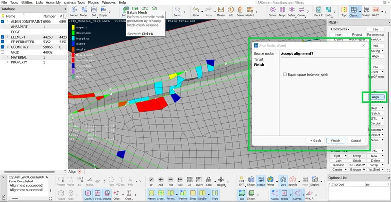
Fig1.13: Executing the 'Align' command to align the nodes.
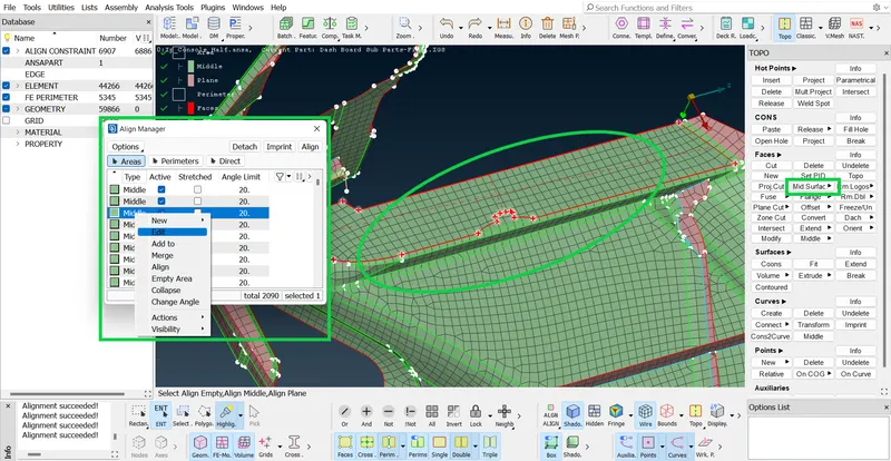
Fig1.14: Defining the surfaces to the elements to repair the base surfaces of the instrument panel.
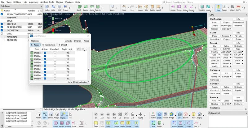
Fig1.15: Repaired base surface of the instrument panel.
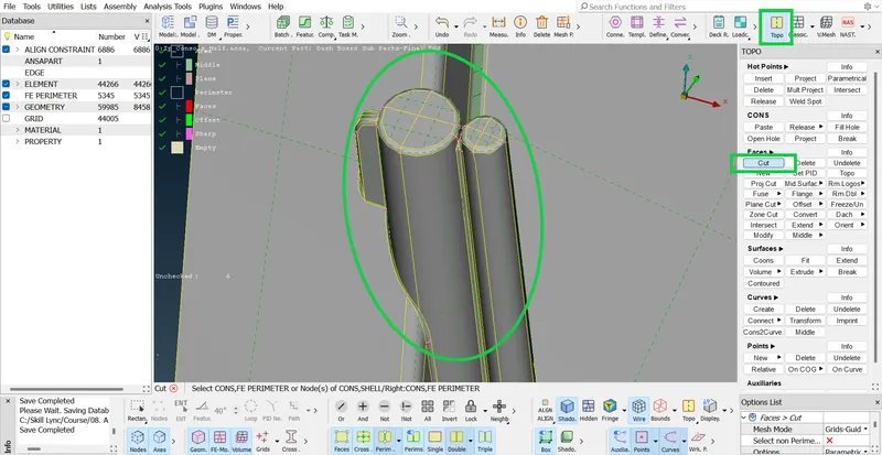
Fig1.16: Creating the cuts of the surfaces of the dog house.
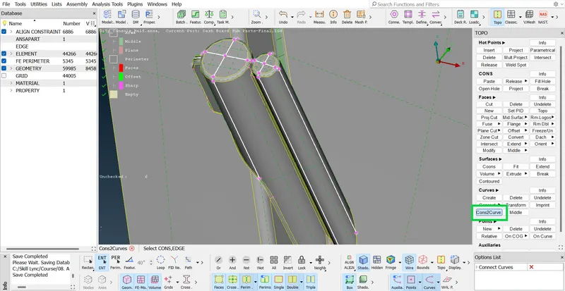
Fig1.17: Executing the 'Cons2curce' command to convert the cons into the curves.
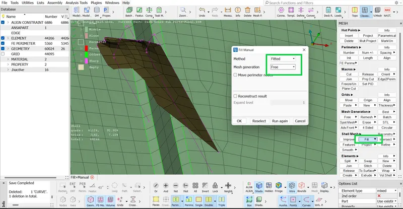
Fig1.18: Executing the 'Fill' command to create shell elements between the curves.
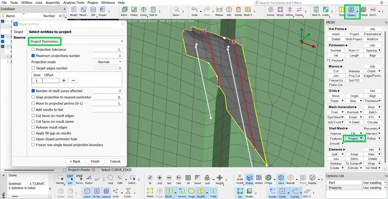
Fig1.19: Executing the 'Project' command to project the perpendicular curves on the normal micro areas.
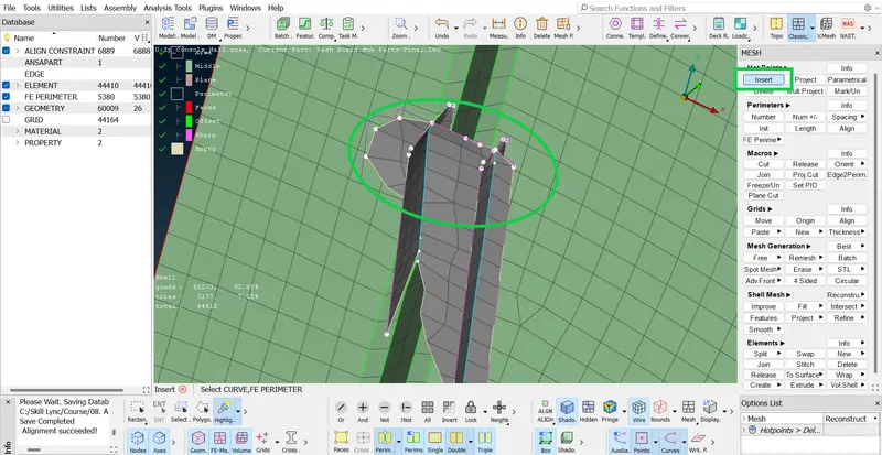
Fig1.20: Creating the 'hot points' wherever necessary.
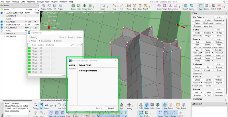
Fig1.21: Defining the faces to the perimeters of the shell elements.
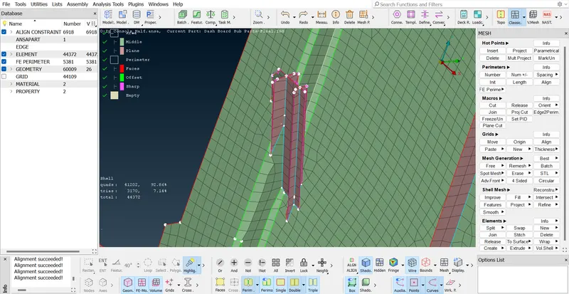
Fig1.22: Defining the planes to the micro shell areas of the elements and projecting them to the base surface.
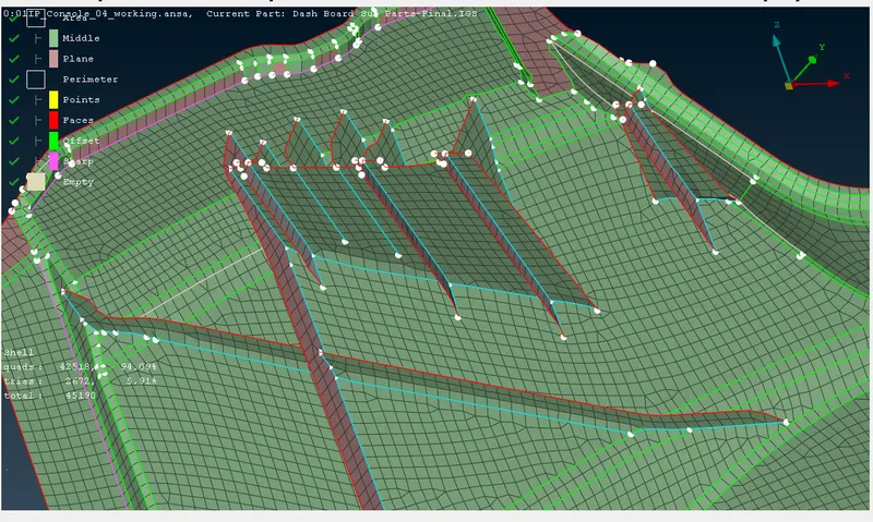
Fig1.23: Repaired base surfaces and features of the instrument panel.
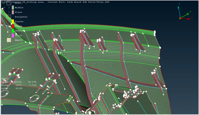
Fig1.24: Repaired base surfaces and features of the instrument panel.
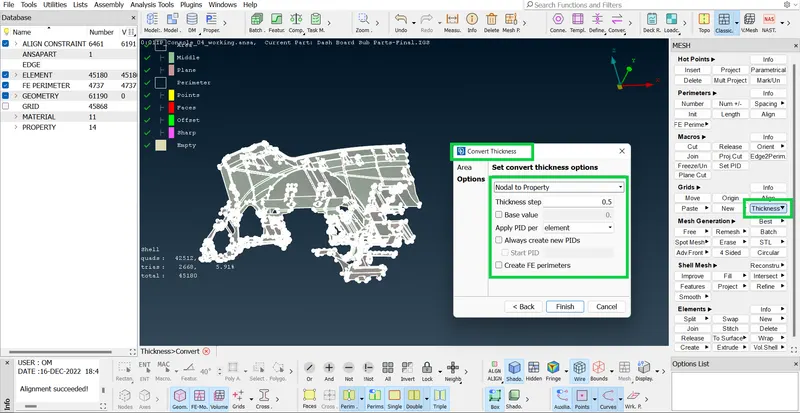
Fig1.25: Executing the 'Thickness (Convert)' command to assign the thickness to the available shell micro areas automatically.
Learning outcomes:
- We learnt and practiced, How to create 2D mesh for plastic components using the 'Casting' approach.
- To obtain the good mesh flow for automotive plastic components with minimum number of elements failing for quality using the Align manager.
- To assign the thickness and other properties to the extracted 2D shell micro areas of the component automatically.
Conclusion:
We studied and practiced the meshing of automotive Intrument panel with proper mesh flow, as per the quality requirements of the automotive standards.