Project 1 - 2D meshing on the instrumental Panel
AIM: Pre-processing of the car instrument Panel using ANSA.
OBJECTIVE:
The main objective for the given component is to check for the geometrical errors and mesh with the given element Quality criteria. At the end, the thickness has to be assigned to FE each feature accordingly.
PROCEDURE :
SWITCH PANEL:
The IP substrate model is loaded into the ANSA GUI using the “File > Open” command then the models is observed in different views using the functions keys.
1.Topology & Orientation ->
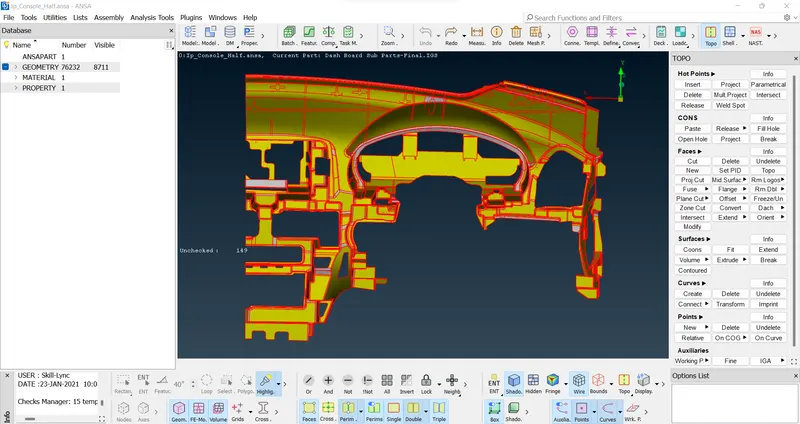
The topology is performed for broken faces using “Faces > Topo” command in the topology module.
And also, we have to give a proper Orientation to the Parent Component, using “Faces > Orient”.
The resolution of the CONS is improved using Auxiliaries > fine from topo module or perimeters >length from mesh module.
2.Geometry Clean-up ->
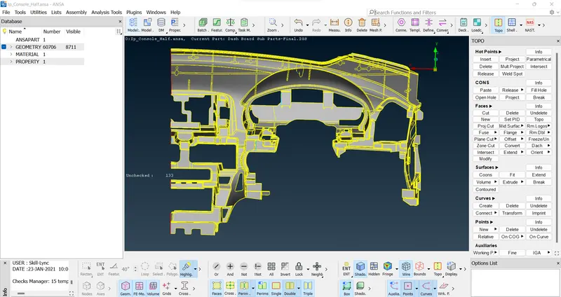
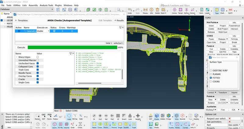
that the model is checked for geometry errors using “Check’s Manager > Geometry” command, in case of geometry errors such as missing cons can be corrected using “Hot Points > Insert/delete” , ”Faces > Elements > delete” for erase disturbed surfaces and then create a new one using “Faces > New” ,and also use Cons > Release > Topo command in TOPO module.
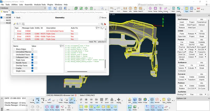
>note: some errors fix by auto-fix option but for others we have to do it by manually,
Casting _ Mid-surface / FE à>
3.Mesh Length ->
Before beginning the meshing process the model is checked for the length between the two hot points since the require target length is 4mm so using “Classic-Mesh> Length>Perimeters/Macros” command it is set to 4mm. for the entire model.
4.Quality Criteria ->
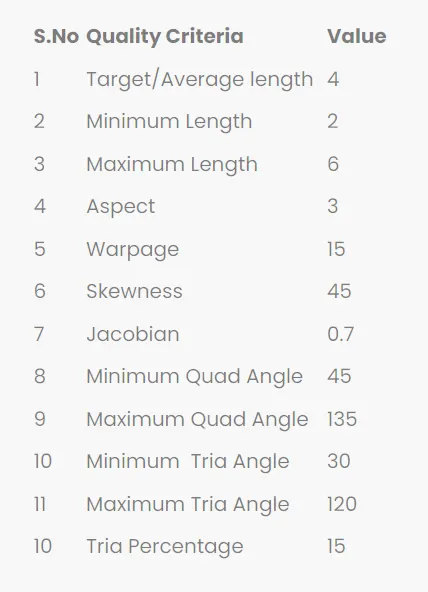
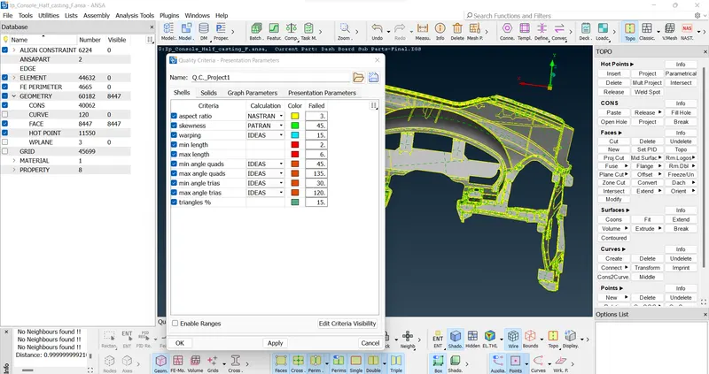
Set-up: We can say that result quality is directly proportional to the element quality. The parameters like skew, included angle, Jacobian, warpage, etc. are the measure of how far a given element deviates from the ideal shape. If we talk about a square which means 90 degrees and equal side similarly equilateral triangle 60 degrees and each side equal. so, we will discuss the quality criterion and try to understand them before assigning them into ANSA environment.
//-NOTE:-
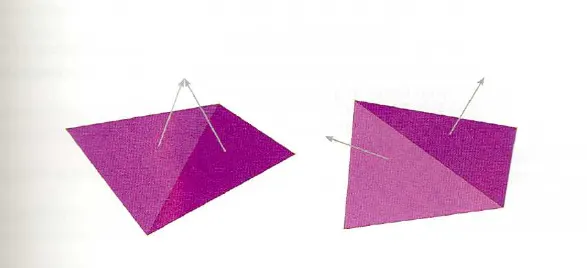
1/ Warp Angle: it is defined as the angle between the normal of the two planes by splitting the quad element along the diagonal. so, the maximum angle allowed between the two possibilities is called wrap angle. wrap angle is not applicable in the triangular element. The ideal value is 0 degree but less than 10 degree is acceptable as good practices.
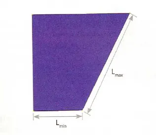
2/ Aspect Ratio: It is defined as the ratio of max element edge length to the minimum element edge length. The ideal value is 1 but less than 5 is acceptable.
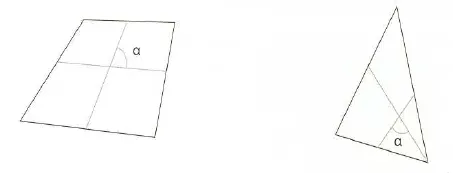
3/ Skewness: If the quad element is not square and has deformation then the skewness defined for as the 90 minus the minimum angle between the two lines joining the opposite mid sides of the element and similarly for the triangular element it is 90 minus the between the line from each node to the opposing mid-side. The ideal value is 0 but less than 45 degree is acceptable.
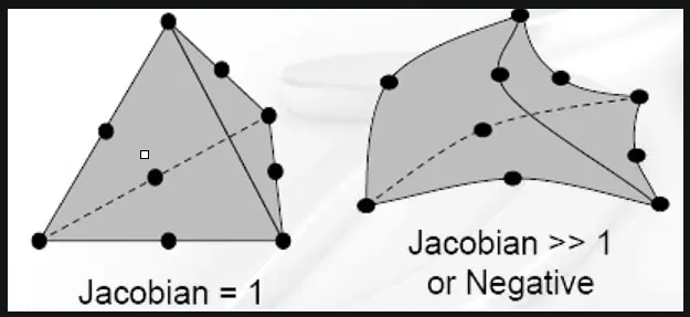
4/ Jacobian: it is the scale factor used in the transformation of the co-ordinated system. (Global to a local coordinate system). This is used for a faster analysis point of view. The ideal value is 1 but greater than 0.6 is acceptable.
5/ Minimum element length: It is very important to check for crash analysis (time step calculation). it is also done to avoid the presence of any zero-length element.
6/ Target element length: It is the size of the element by which we can get the nearer approximate value of the result compared to the experimental result.
- To set up the quality criteria press the F11 key and check the boxes of the parameters of the required quality with required values and apply.
5. Mesh Parameters ->
Also, set the meshing parameters before proceeding to Casting.
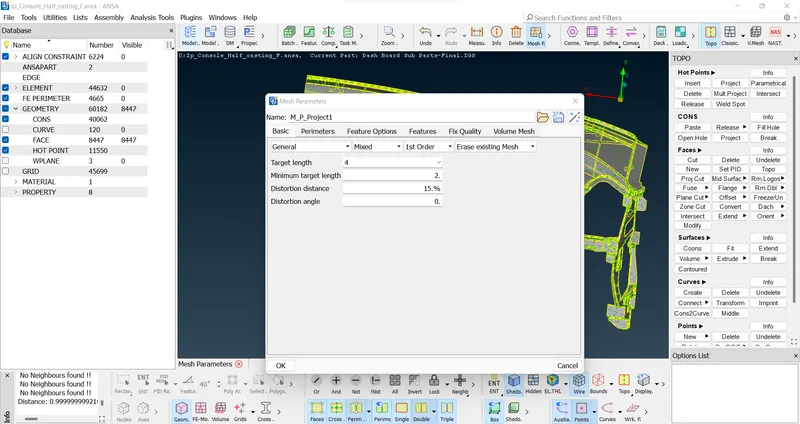
//-NOTE: so now we can start meshing the component individually but before we start meshing, we will know about the 2D meshing and its good practices to follow to get a good mesh flow.
2D Meshing/shell meshing
The type of element allowed in 2D meshing are
- Quad Elements.
- Tria Elements.
- parabolic Tria.
- parabolic Quad.
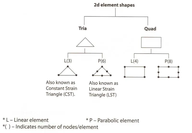
>>As we know that the quads elements are better than triangular elements and parabolic elements are better than linear elements
But if the quads are better than tria then what is the need for using tria elements?
- For better mesh transition.
- Avoid poor quality element in a complex geometry.
- better mesh flow.
- Tetra meshing (trias to tetra length).
- Mold flow analysis.
6. Casting ->
Since this is a complex model so, Casting option taken for taking Mid-surface / FE automatically. And after Align elements by Align Manager.
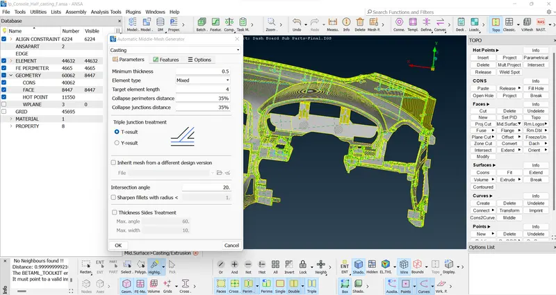
>Auto generated FE by Casting Method....
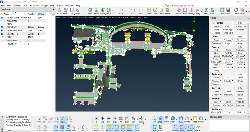
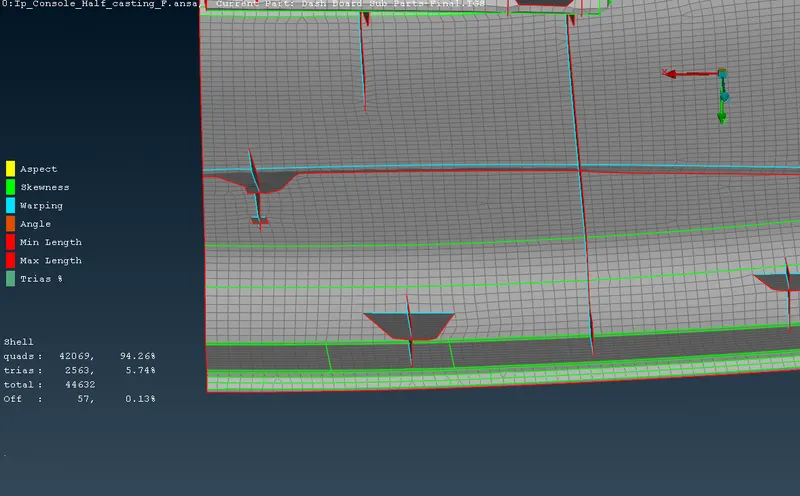
-After Casting we can observe that some features are not have proper shape according to the parent component so, we have to check it and fix it Mannualy. (First we have to set the base elements proper then go for features.)
7.Dog house ->
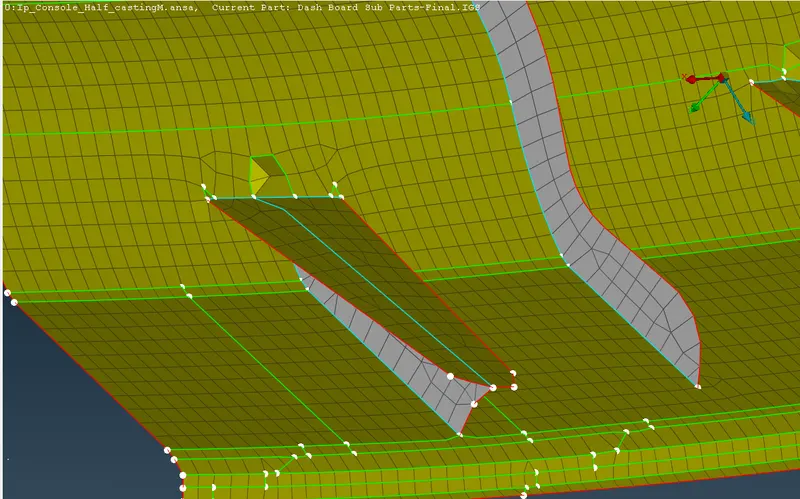
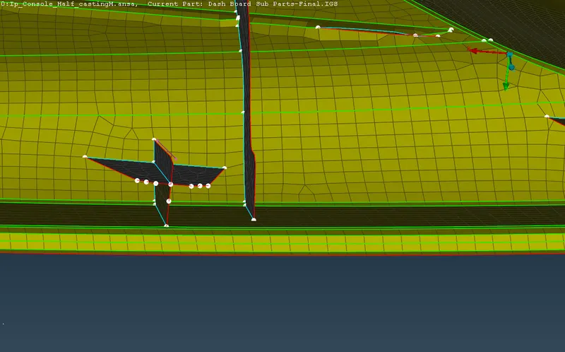
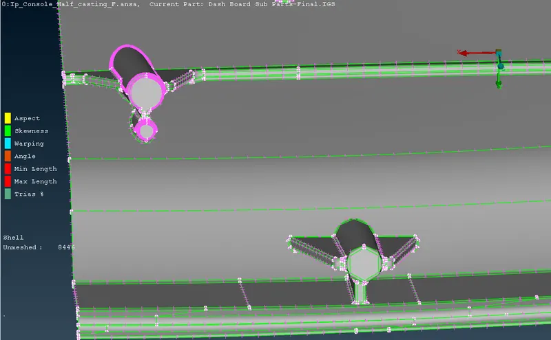
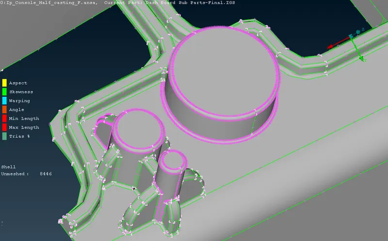
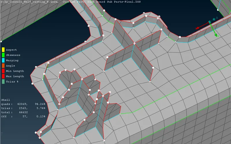
Dog houses are critical area in the component. So, we have to recreate it reference form parent model and work manually, using join, delete disturbs elenents, create-curve, curve-middle, feat2curve, cons2curve, and then create new elenents using Mesh > elements > new, or Shell mesh > Fill, and after by using the align manager we correcting the auto_generated FE.
8.Align manager ->
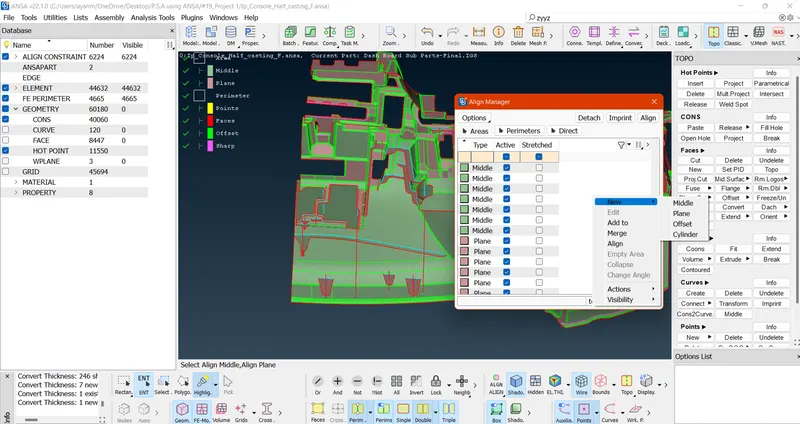
Align manager is used to ensure the automated generated mesh is align to middle of surface. by using the align manager we correcting the disturbed FE if any.
-Also we can delete elements and recreate it by Shell Mesh > Fill option, & after that newly created elements are add to the Align Manager by right click on it > new > choose the option accordingly with Middle / Plane / Offset / Cylinder. After adding in Align Manager the elements faces/perimeters get position accordingly to the parent component positions.
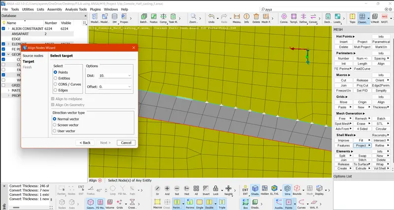
-Also we can use Align Nodes Wizard using Mesh > Grid > Align for getting back Nodes original positions.
9.Improve the mesh flow and quality of mesh ->
- smoothing the mesh: (mesh module > shell mesh > smooth).
- reconstruct the mesh: (mesh module > shell mesh > improve[reconstruct/reshape/smooth/fix]).
- improve the quality of mesh: (mesh module > elements > split/swap/join/stich).
- insert or delete hot points: (mesh module > hot points > insert/delete).
- to Paste : To paste nodes helps in moving elements backwards: (Mesh > Girds > Paste).
- to increase or decrease elements number: (mesh module > perimeters > NUM+/-).
- to cut or join the face: (mesh module > macro > cut/join).
10.Assigning the Thickness ->
Assign the proper thickness automatically by using Classic-Mesh > Grids > Thickness > Convert (then select the FE).
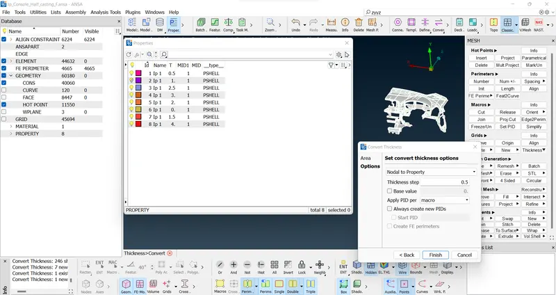
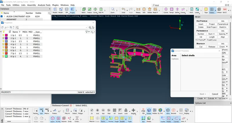
- The elements which fail for quality can be viewed by using the Draw mode toolbar > hidden option and corrections are done for the elements which fail for quality.
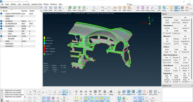
-A total of 44632 elements, with 5.74% trias, & 57 or 0.13% OFF elements were left out as they are unavoidable because of features & triple Cons lines.
>>shell as solid....
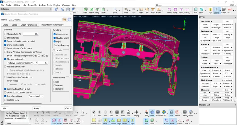
- The thickness assigned to the model can be viewed using utilities > quality criteria > presentation parameters > Draw shell as solid.
Learning Outcomes:
- Effectively extract Casting Mid-surface /FE.
- Assigning PID’s automatically in Casting Method.
- Rearranging construction lines.
- Geometry Check.
- Mesh refining.
- Align Manager uses.
- Assign Thickness to PIDs.
CONCLUSIONs:
In complicate models. Casting mid surface /FE & Align Manger effective used and element failure between triple cons having narrow regions cannot be eliminated.
Although Casting process take approx~ a hour time but in this process we don't go for Mid-surface, geometry clean-up, Mesh accordingly. Here we get the FE directly and fix the disturb features and using Align Manager align faces and perimeters accordingly with the parent model, the processes take alternatively & simultaneously when work in the FE.
FINAL MODEL LINK: