Project 1 - 2D meshing on the instrumental Panel
Project 1 - 2D meshing on the instrumental Panel
Aim
For the given component, check for the geometrical errors and mesh with the given element Quality criteria. After meshing the component the thickness has to be assigned.
Write a detailed report on your meshing process and also mention which method you used to extract the mid-surface along with the reason.
|
S.No |
Quality Criteria |
Value |
|
1 |
Target/Average length |
4 |
|
2 |
Minimum Length |
2 |
|
3 |
Maximum Length |
6 |
|
4 |
Aspect |
3 |
|
5 |
Warpage |
15 |
|
6 |
Skewness |
45 |
|
7 |
Jacobian |
0.7 |
|
8 |
Minimum Quad Angle |
45 |
|
9 |
Maximum Quad Angle |
135 |
|
10 |
Minimum Tria Angle |
30 |
|
11 |
Maximum Tria Angle |
120 |
|
10 |
Tria Percentage |
15 |
OBJECTIVE:
The main objective for the given component is to check for the geometrical errors and mesh with the given element Quality criteria. At the end, the thickness has to be assigned to FE each feature accordingly.
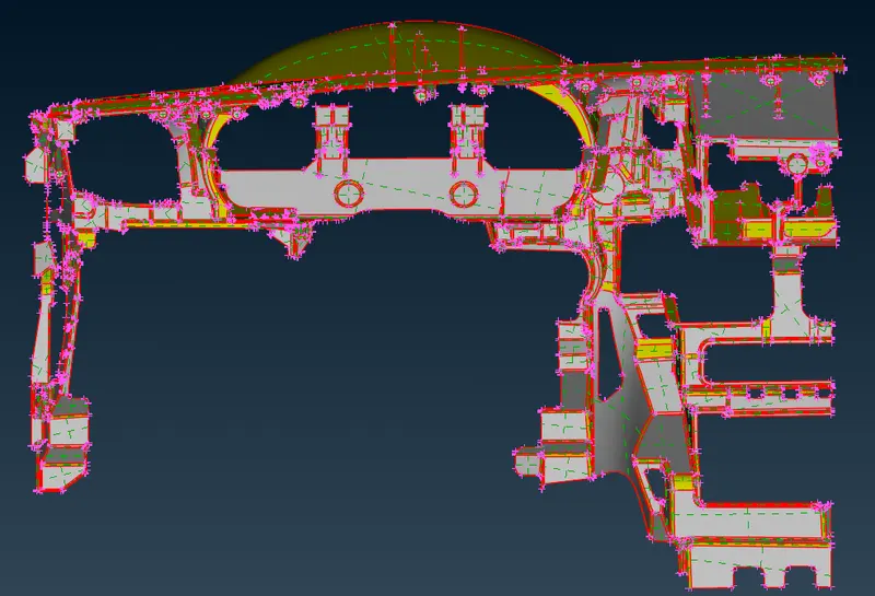
Imported Cad Geometry
METHODOLOGY in Short : Import Cad Geometry and do Geometry clean-up with no topological error-->TOPO -->Setup Quality criteria and mesh parameters --> MESHING AS PER CRITERIA--> ASSIGNING THICKNESS PROPERTY
PROCEDURES:
In TOPO
Geometry checking
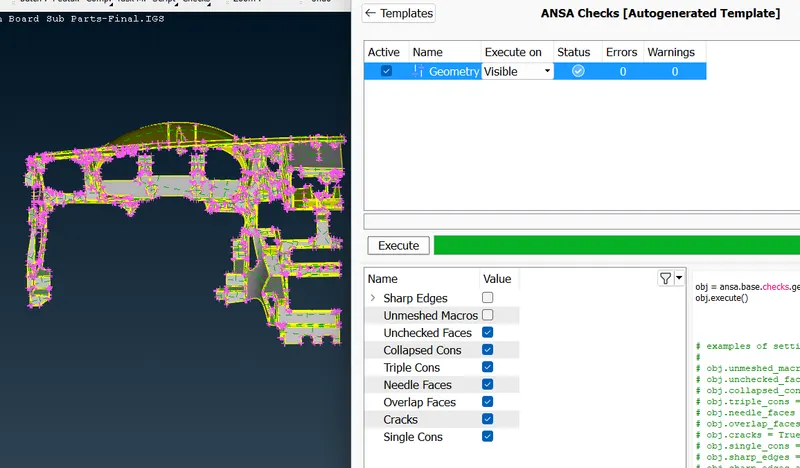
TOPO
After downloading the drawing Geometry, release cons and apply TOPO. Then go for a geometry check. Normally if cons are generated select all then clear it by Right click and fix. If not clearing tough fix manually. In this case after selecting all, go for right click and fix. All errors are cleaned and geometry is perfect. If not go for individual checks and cleaning.
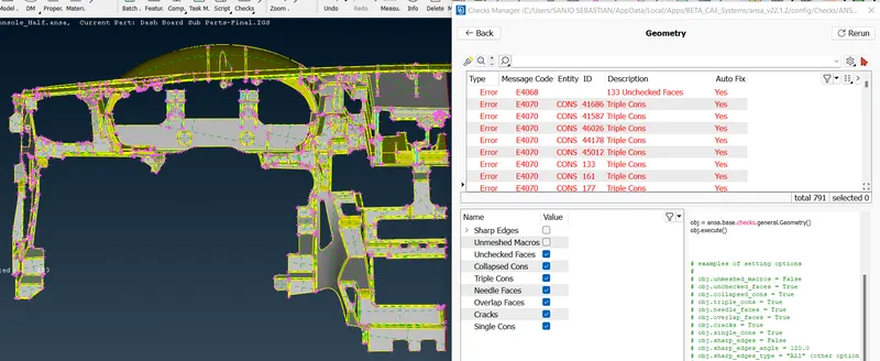
Geometry Checks and Fixing it
Single Cons(represented by red colour lines) - Edges which are shared with only one surface should be single cons. Single cons denote there is no connectivity between the surfaces in the model.
Double Cons(represented by yellow colour lines) -If any edge shared with two surfaces the that line is called Double Cons.
Triple Cons(represented by cyan colour lines) – if any edge is shared with three or more than three surfaces then that line is called triple cons.
Topology describes how elements are bounded and connected and Geometry describes the shape of each element.
Locking
The next part is locking the parent parts in order to take parent part alone.
Save
Save the settings, from tools- settings and save the file
Quality Criteria
Apply the quality criteria given, by pressing 'F11'.
Go to- presentation prameters- put tick in elements
Enable range- apply - okay
Then save the settings.
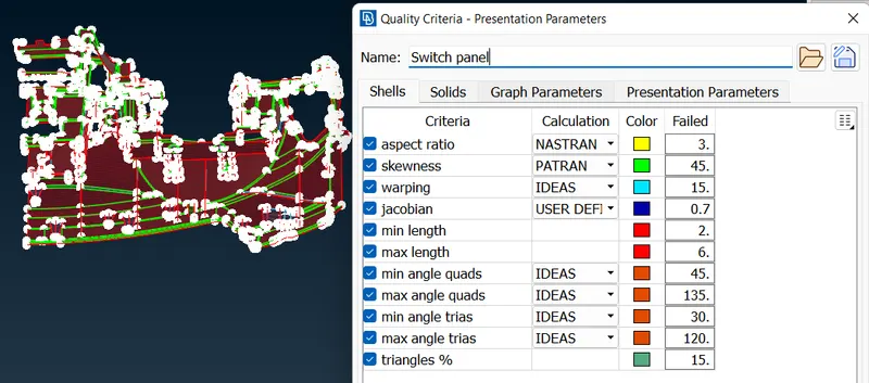
QUALITY CRITERIA
Mesh parameters
Go to-tools-utilities-mesh parameters
Type of mesh- general
Element Type- Mixed( It’s a mix of quad and tria elements)
Order of element- First order
Save the setting for future reference
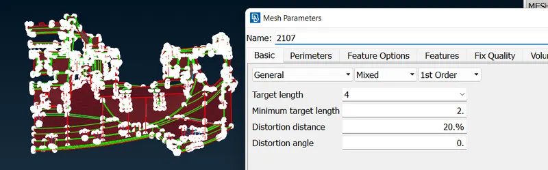
MESH PARAMETERS
- JACOBIAN--Is a measure of the deviation of a given element from an ideally shaped element.the jacobian value ranges from -1.0 to 1.0,where 1.0 represents aperfectly shaped element.
- WARPAGE--Is defined as angle between normals to two planes formed by splitting the quad element along diagonals.max.angle out of the two possiblities is reported as warp.
- ASPECT RATIO
Is the ratio maximum edge length to the minimum edge length of an element.the ideal value of the aspect ratio is 1.however the aspect rato of less then 5 is accepted.
- SKEWNESS
Is the angular measure of element quality with respect to the angles of ideal.
CASTING -
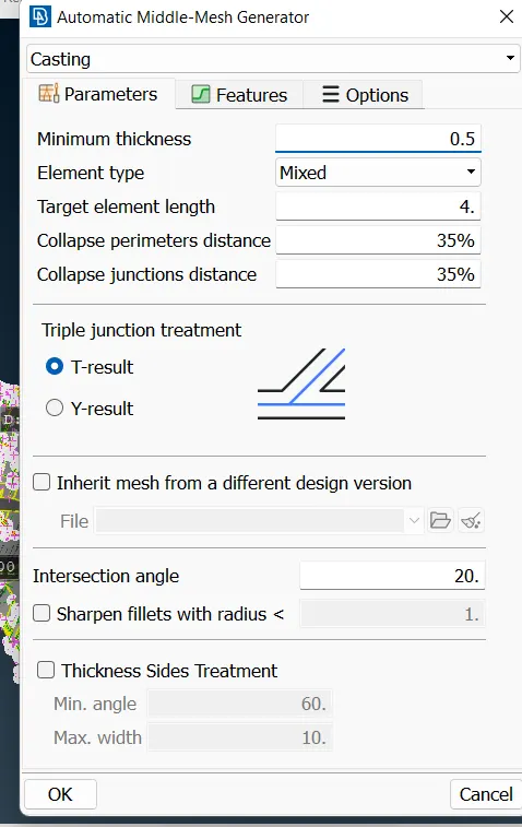
CASTING
- Since this is a complex model so, Casting option taken for taking Mid-surface / FE automatically. And after Align elements by Align Manager.
- Auto generated FE by Casting Method.
- After Casting we can observe that some features are not have proper shape according to the parent component so, we have to check it and fix it Manually. First we have to set the base elements proper then go for features.
- Assign thickness by midsurface- calculate midsurface thickness.
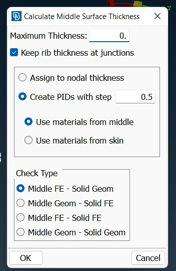
ASSIGNING THICKNESS
Dog house -
- Dog houses are critical area in the component. So, we have to recreate it reference form parent model and work manually, using join, delete disturbs elements, create-curve, curve-middle, feat2curve, cons2curve, and then create new elements using Mesh > elements > new or Shell mesh > Fill, and after by using the align manager we correcting the auto generated FE.
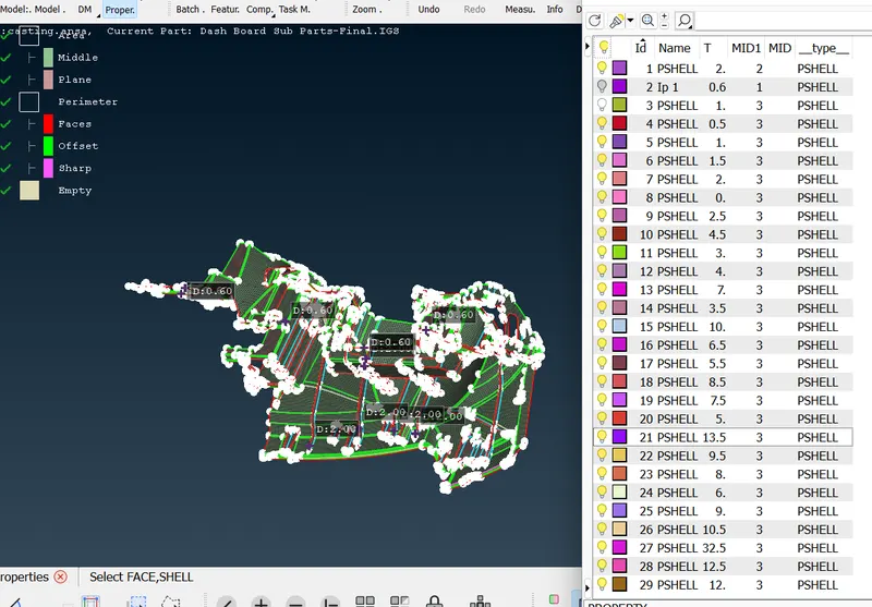
PROPERTIES
ALIGN MANAGER -
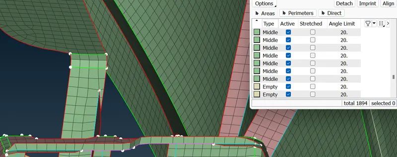
ALIGN MANAGER
- Align manager is used to ensure the automated generated mesh is align to middle of surface. by using the align manager we correcting the disturbed FE if any.
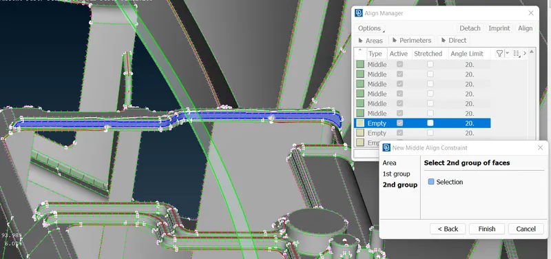
ALIGN MANAGER WHILE USING MIDDLE
- Also we can delete elements and recreate it by Shell Mesh > Fill option, & after that newly created elements are add to the Align Manager by right click on it > new > choose the option accordingly with Middle / Plane / Offset / Cylinder. After adding in Align Manager the elements faces/perimeters get position accordingly to the parent component positions.
- Also we can use Align Nodes Wizard using Mesh > Grid > Align for getting back Nodes original positions.
Split in elements
Used to delete unwanted trias and to generate a straight line by splitting the lines.
Swap
Used to delete unwanted trias and to redirect the line to another node.
Reconstruct
If the mesh flow is not perfect go for reconstructing the mesh and rerunning them will make perfect.
Smooth
If the mesh flow is not perfect and after split usage and lines are not keeping uniform distance go for smooth function in the mesh to make perfect line mesh.
Improve
Uses both smooth and reconstruction at same time.
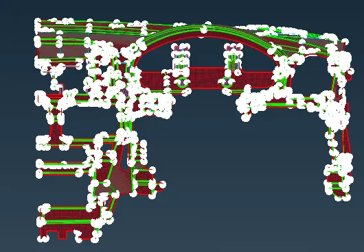
FINAL IMAGE
Learning Outcomes:
Able to do topological clean-up with no errors.
Assigned separate PIDs for different surfaces.
Done the casting with assign thickness.
Aware of all the quality criteria and quality parameters during mesh generation.
Understood about mesh generation and implemented mesh generation for complex parts.
Learned how to improve mesh flow and remove trias to achieve better mesh flow.
Understood all the concepts regarding mid surface generation and meshing in ANSA.
Conclusion
In this project, casting method is used for assigning midsurface with meshing. Then the model is aligned using align manager and thickness is asigned using middle surface thickness. We should try to remove off element as much as possible but off element at corner including triple cons and sharp edges has been ignored.