Project 1 - 2D meshing on the instrumental Panel
Aim :- For the given component, check for the geometrical errors and mesh with the given element Quality criteria. After meshing the component the thickness has to be assigned.
Solution :-
1) Import Model :-
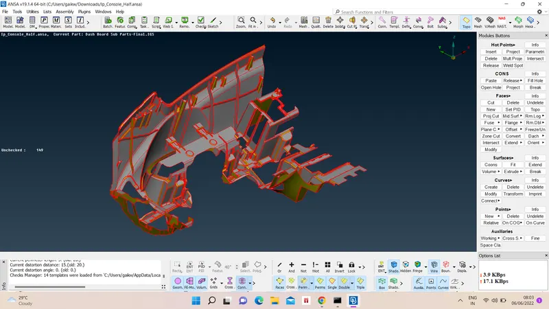
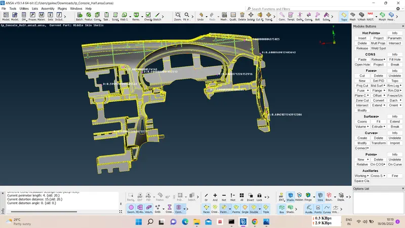
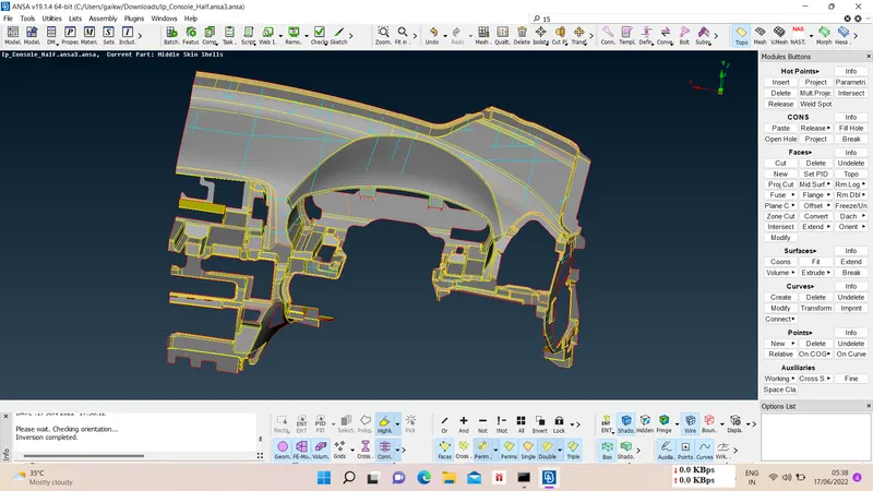
Open model from file menu. Topo the model and measure the thickness at different locations using measure option for further midsurfacing purpose .
2) Geometry cleanup :-
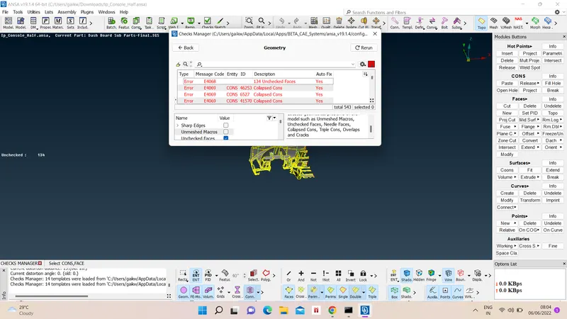
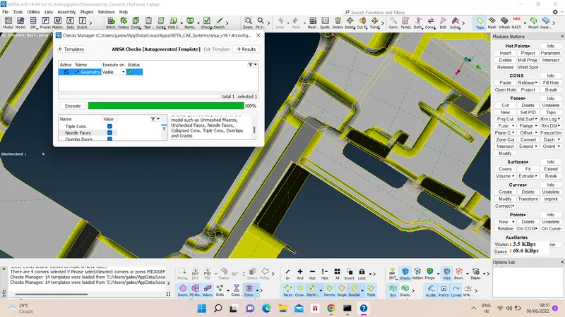
We have to check for geometry cleanup for given model, for that go in checks manager option and choose geometry check option and execute. Ideally our model should have no errors with 100 % geometry cleanup, so we will fix the errors through automatic fix option. In this model we gonna ignore triple cons check as model gonna have triple cons in it.
Geometry check results are -
3) Mid surfacing -
We can take mid surface either manually or automatically too. For manual mid surface we choose Offset option and give distance value with appropriate direcrtion and for automatic midsurface we use Automid option from Faces option.
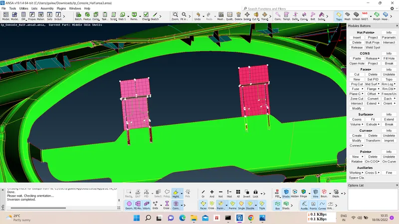
- Here for main part of model automid option isnt giving better results, as model has many features with complicated geometry. So we used manual midsurfacing using offset option for main part.
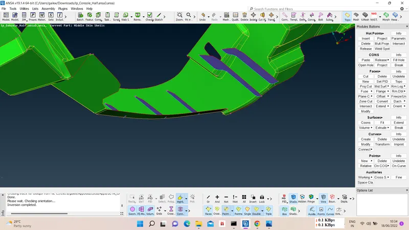
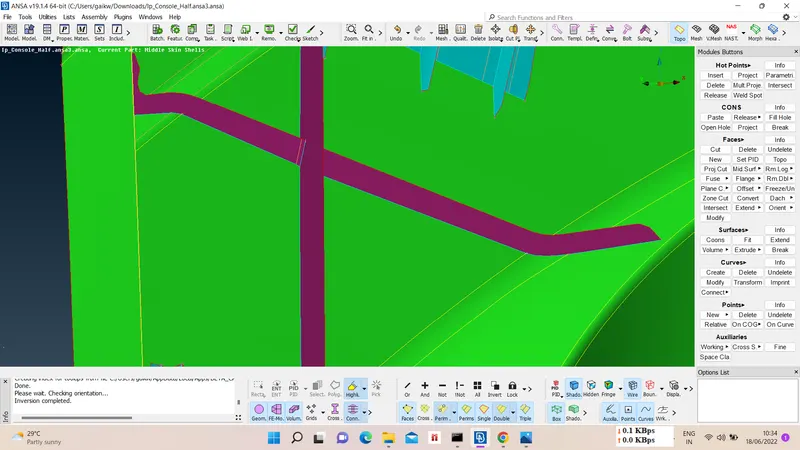
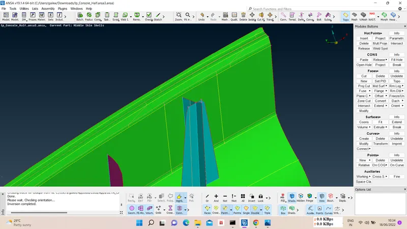
- For small ribs we used Middle option from faces and for big ribs we did manual midsurfacing using offset option.
- For dog houses midsurfacing, we used const2curve option from curves to capture cylindrical area and with middle, extend, new face option we midsurfaced them.
- There are some features which we can midsurfaced using casting auto mid gneration like - faces - midsurface- casting -select feature - provide min. thickness and target element length - ok.
So results of midsurfacing are as follow -
4) Property Assigning to mid surfaces :-
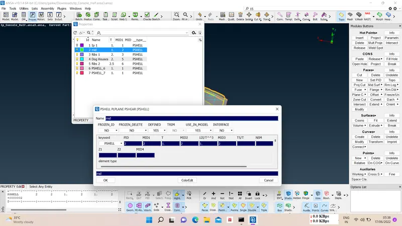
The newly formed midsurfaces has to assigned with new PID. For that we choose Set PID option and select faces, after that we create new Pshell card with appropriate number, thickness and color for given chosen components.
5) Meshing Preparations :-
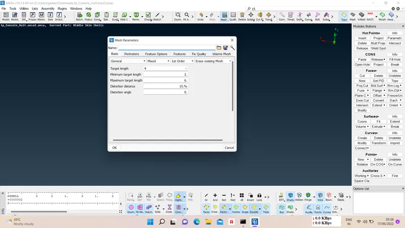
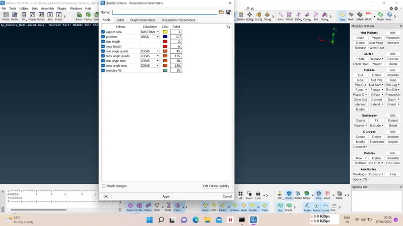
Before starting meshing we have to give model mesh parameters and mesh quality criteria.
For mesh parameters Utilities > mesh parameters > set target length, max and min length > ok.
For quality criteria Utilities > quality > apply quality criterias > ok.
6) Meshing :-
We can choose different method for meshing but for best result we choose Mesh generation > sopt mesh > select faces > confirm.
After meshing mesh improvement has to be done to achieve quality criteria, so we have to reconstruct mesh Shell mesh > Reconstruct/smooth > select area of mesh > give try and rerun mesh.
Further failed mesh pattern like trias and off elements are removed using split, swap, join, smooth, etc. options.
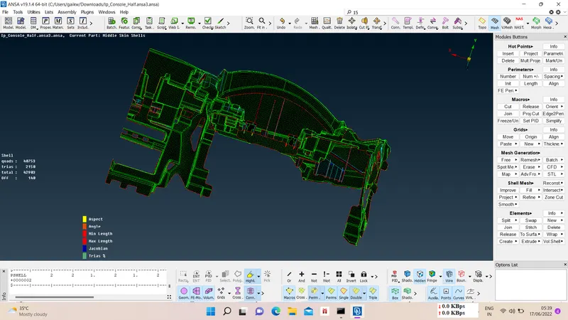
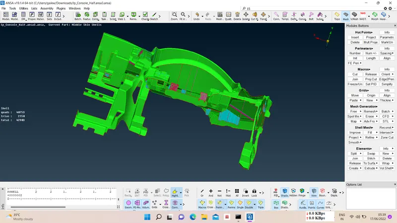
Mesh results are as follow -
G-drive link :-
https://drive.google.com/file/d/1DcJ2skI52ss2lgH7SGsJQh0_TE-8gvhr/view?usp=sharing