2D meshing on the instrumental Panel using ANSA
AIM :
To Check for the geometrical errors, take mid-surface and mesh with the given element Quality Criteria for the given Component.
OBJECTIVE :
For the given component, check for the geometrical errors and mesh with the given element Quality criteria. After meshing the component the thickness has to be assigned.
|
S.No |
Quality Criteria |
Value |
|
1 |
Target/Average length |
4 |
|
2 |
Minimum Length |
2 |
|
3 |
Maximum Length |
6 |
|
4 |
Aspect |
3 |
|
5 |
Warpage |
15 |
|
6 |
Skewness |
45 |
|
7 |
Jacobian |
0.7 |
|
8 |
Minimum Quad Angle |
45 |
|
9 |
Maximum Quad Angle |
135 |
|
10 |
Minimum Tria Angle |
30 |
|
11 |
Maximum Tria Angle |
120 |
|
10 |
Tria Percentage |
15 |
PROCEDURE :
IMPORTING CAD MODEL AND GEOMETRY CLEANUP :
1. Import the given CAD Model in ANSA by using File-->Open.
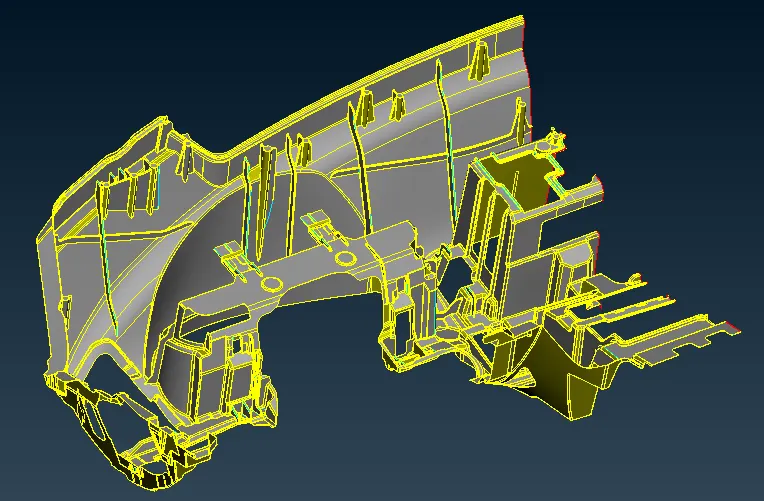
Fig: Dashboard Model
2. After Importing the CAD Model in ANSA, Go to Tool-->Checks-->Geometry for Geometry Clean up.
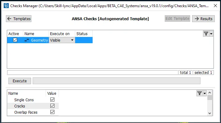
Fig: Checks Manager Window
3. In the above Checks Manager window click Execute to check any error occurred in Hood Model and fix the Error and Cleanup the Geometry.
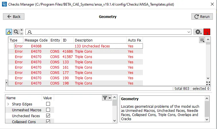
Fig: Error in CAD Model
4. In The above window, an error has occurred in the given Geometry model. Check the error showing in the Model and fix the issue and clean up the Geometry.
5. While resolving the error, Right Click on the error which is going to resolve and click Show only option.
6. It will show only that Unchecked Faces. Using Face-->Delete Option to delete the Unchecked Faces.
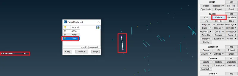
Fig: Deleting Unchecked Faces
7. After deleting the Needle Face, that error has been resolved. Similarly, all errors have to be fixed, and again Click Execute in the Checks Manager, and 100% Geometry Cleanup is to be verified.
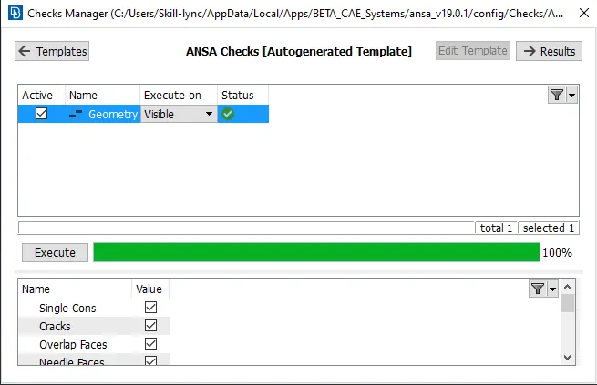
Fig: Geometry Cleanup
CREATING MID-SURFACE :
8. After geometry Cleanup and Mid-surface has to be created separately for each component.
9. Go to Topo-->Faces-->Offset option and select the face and Create Midsurface.
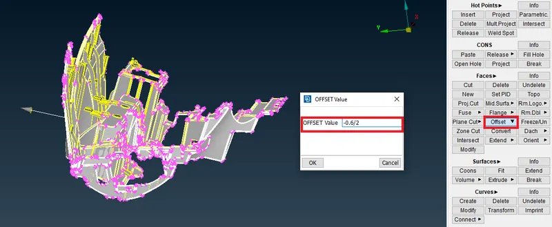
Fig: Extracting Midsurface (Using Offset option)
10. For Dog houses, Go to Topo-->Curves option and Create curves in the dog houses.
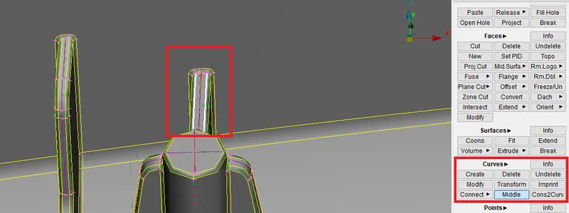
Fig: Creating Curves
11. After creating a curve, Go to Faces-->New option and create a Faces between the curves.
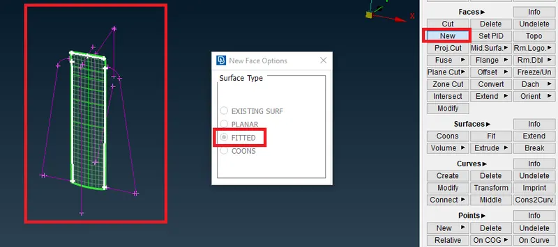
Fig: Creating New Faces
12. By using the above method, creating a mid surface for all Dog houses and Ribs.
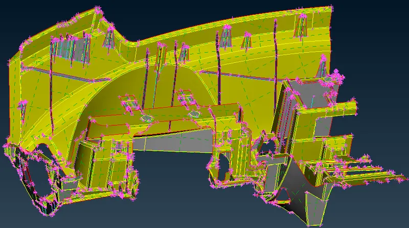
Fig: Mid-surface for CAD Model
13. After created a Mid-Surface, Click Faces--> Set PID option and create New PID for Each component in the properties.
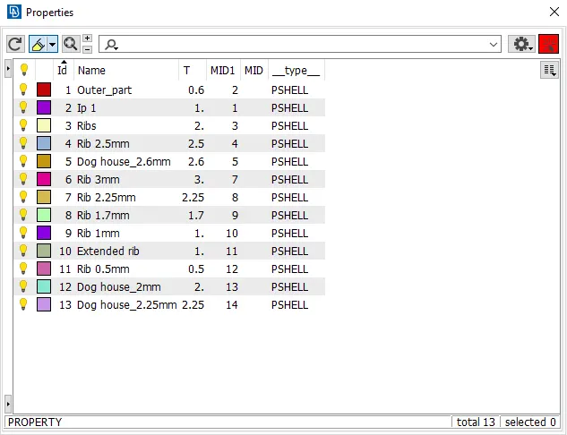
Fig: PID for above Mid-Surface Components
MESHING :
14. After Creating a Mid-Surface, set the given Quality Criteria for the Component.
15. Go Utilities-->Quality Criteria Option and assign the given Quality Criteria Values.
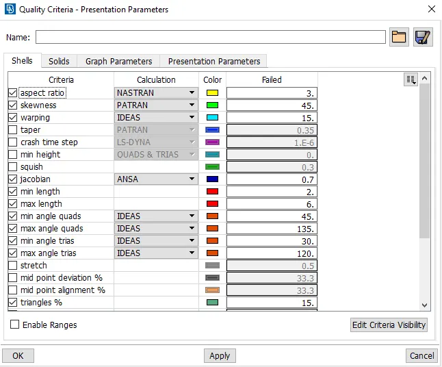
Fig: Quality Criteria
16. After assigning the Quality Criteria for the Component, Go to Utilities-->Mesh Parameters and assign the Average Value, Minimum and Maximum Value for Meshing.
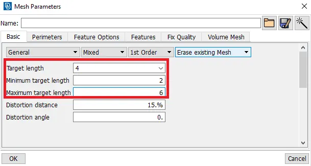
Fig: Mesh Parameters
17. Go to Mesh-->Perimeters--> Length Option and Select the Component to Mesh and enter the Value of Perimeter Length and Macro Length for Meshing.
18. Go to Mesh-->Mesh Generation Option and Select the Mesh type to mesh the component.
19. Select the Mesh type in the Mesh generation and Select the Faces to mesh and Mesh will be generated.
20. Use Shell Mesh-->Reconstruct option to rearrange the Mesh and Use Shell Mesh-->Smooth Option to arrange Mesh lines equally within the Selected Surface and solving the Quality criteria issues.
21. Use Grids-->Paste or Elements-->Split / Swap / Joint Option to eliminate or reduce the trias and get better mesh flow.
22. Check if there are any off elements is present and reduce the off elements and some areas of off elements will be acceptable.
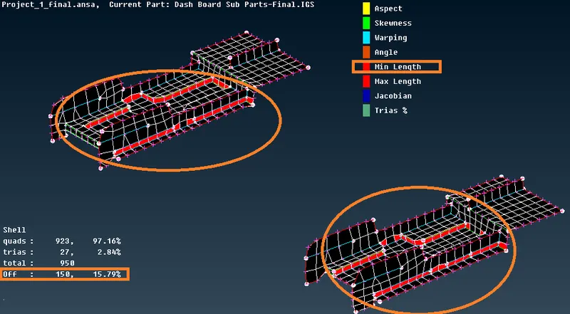
Fig: 150 Off elements due to min length criteria
23. For better feature capturing, in some areas 150 Off elements due to min length criteria which are shown above, and in other some areas 30 Off elements are due to aspect, Skewness, warping, jacobian.
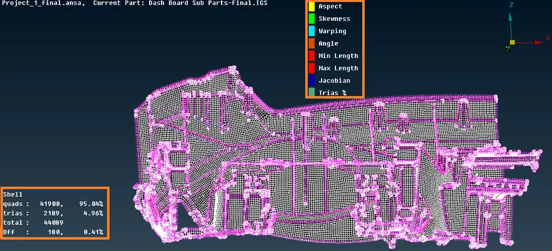
Fig: Dashboard Mesh with Quality Criteria
24. Parent Surface thickness Value is to be Provide for the Mesh Component. Go to Lists-->Properties option and Assign the Thickness Value.
25. Go to Quality Parameter-->Presentation Parameters and select Draw shell as solid, click Apply and Ok.
RESULT :
Checked for the geometrical errors & taken mid-surface and meshed with the given element Quality Criteria for the given Component and assigned thickness for FE Model.
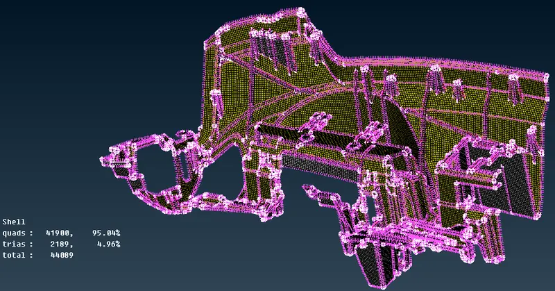
Fig: Dashboard FE Model with assigned Thickness