Project 1
INTRODUCTION
WIRE HARNESS ROUTING:-
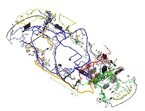
Every automotive vehicle has the electrical distribution system installed in it.It starts from the battery system and distributed to the all components of the car like headlights,ignition systems,tail lamps,infotainment system etc..,thus organising and arranging the vehicle elctrical wires from the connectors to their respective fuctional equipment is a challenging task.Cause the wires in the automotives are subjected to various distrubances that will wear and tear them which will crack open and lead to the shot circuit or disfunction of the elctrical systems.For example the wire bundles for spark plug in the engine are subjected to heat around 200 degree celcius and the vibrations due to the engine,it might cause the damage in the bundle which will lead the short circuit.Somes the water tries to enter through the bundle and lead to short circuit.So, there are also countless factors which effect the wire bundles.So,for the effective and economic functioning for the EDS we do the wire harness routing using the CAD sofwares.These tools are again divided into two types E - CAD and M - CAD depending upon the fuctioning.E - CAD is the electrical defination of 2d circuit generation done by the electrical engineer and M - CAD is the physical routing of the wire bundles and the supoorts,connectors,mounting parts,clips,clamps etc..,This will not only develop the effective routing but also saves lot of time and money.
AIM:-
- To generate the wire harness routing for the given engine part.
- To generate the routing in the effective way which the bundles do not get damged due to the engine or vibrations.
- To add the necessary protective devices and guiding channels.
GIVEN ENGINE PART:-
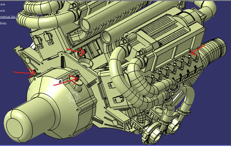
The input for the wireharness,engine 3d part model is given.The positions of the connectors,transmission sensors,thermal sensors are given as shown in the below figure.
- ELECTRICAL WORKBENCHES:
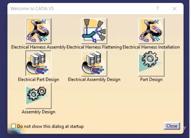
1. ELECTRICAL PART DESIGN:- To define the the part as the electrical
2. ELECTRICAL HARNESS ASSEMBLY:- To harness the wire bundle using the electrically defined parts
3. ELECTRICAL INSTALLATION:- Immedietly when the routing is started through the harness assembly the
installation workbench opens in which you can add branch points, delete branches and add protective covering etc.,
4. ELECTRICAL ASSEMBLY DESIGN:- To assemble the inter connections with already defined electrical properties
5. ELECTRICAL HARNESS FLATTENING:- To flatten your harness bundle and use it to generate the 2d drawing which is fed as an output for the manufacturing.
- STEPS TO GENERATE THE WIRE HARNESS:-
STEP:- 1. DEFINE THE COMPONENTS AS ELECTRICAL:-
- To define a component as electrical open the electrical part design and import the part.
- select the desired component and define it accordingly.The below options reperesent the defination for unique component
- Choose the appropriate part and define the no.of terminals for connectors what type of connectors its is etc..,

- Example while defing a 2-pole connector a dailog box pop ups as shown
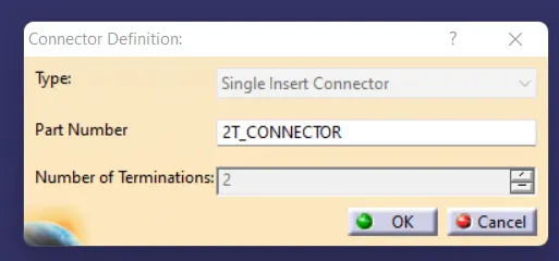
- here define the type of connector and enter the no.of terminals associated with it
- when it is defined the electrical defination symbol is add to feature tree
- After defining the component define the geometrical parameters for the component
- for defined component we need to define the geometrical parameters using the below options

- After defining the electrical part which is connector here next to define geometrical parameters using the above options this dialog box opens
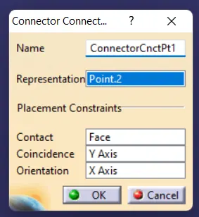
- select the connector then select the point following with coincidence face and orientation face from the axis system defined.
- Next select the bundle connection point option the following pop up opens
- Similarly while defining the support parts we just define the part as electrical using the options.
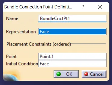
- When this is opened select the connector and select the necessary attributes as defined as previous one.
- While defining the support itself we have the entrry points and respective planes while defining the support parts as electrical.
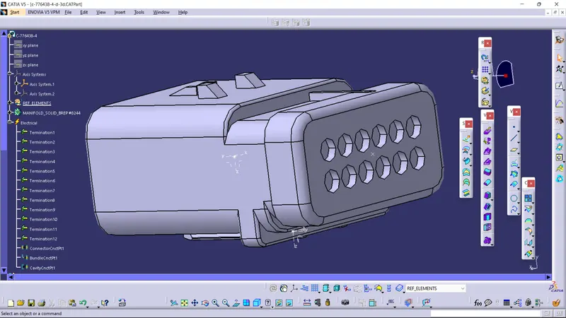
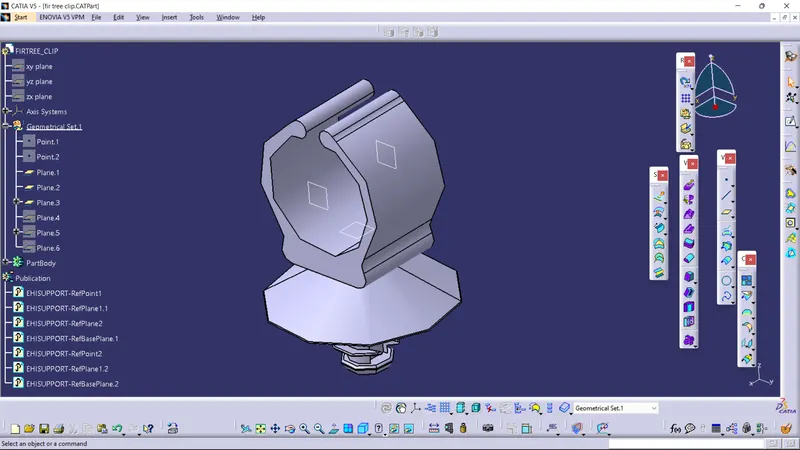
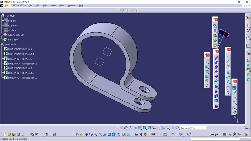
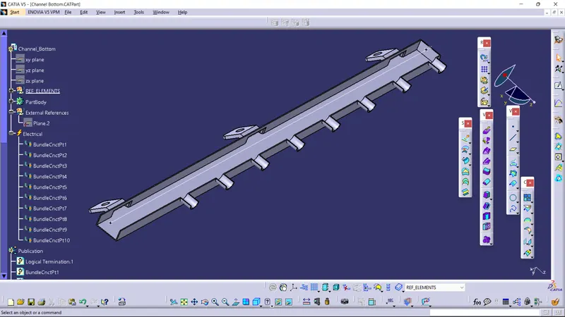
VARIOUS COMPONENTS DEFINED AS ELECTRICAL:-
4 pole connector
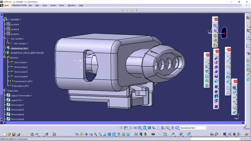
2 pole connector
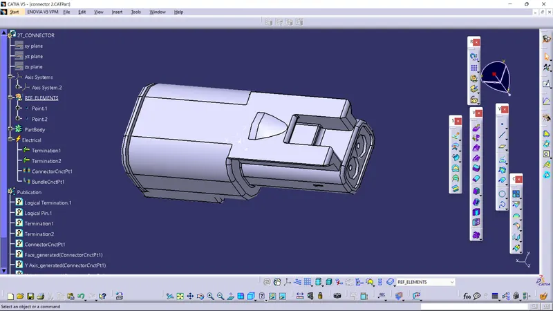
8 pole connector
firtree clip
P clamp
Guiding channel
STEP:- 2. POSITION THE CONNECTORS AND SUPPORT PARTS IN THE DEFINED LOCATIONS:-
- After all the parts are defined as electrical we have to position them in the allocated locations
- While constructing the assembly,the main assembly is called the CONTEXTUAL ASSEMBLY which is main assembly.
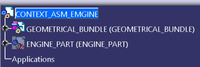
- In the contextual assembly we have the GEOMETRICAL BUNDLE in which all the defined electrical parts should be included and in this set only the harness product is inluded.
- After import all the parts into the geometrical bundle product switch to assembly workbench and position each parts in their required position as shown.
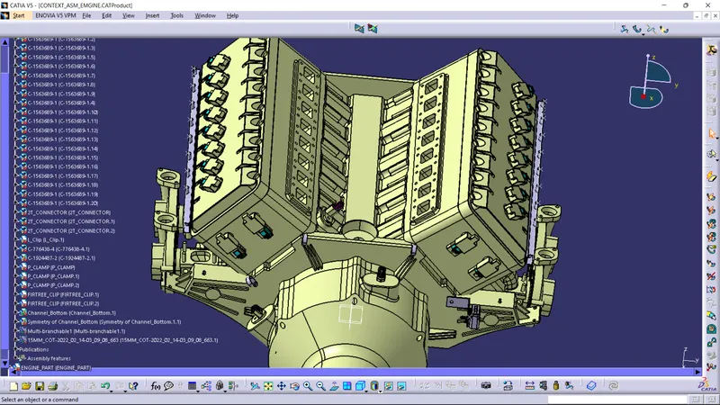
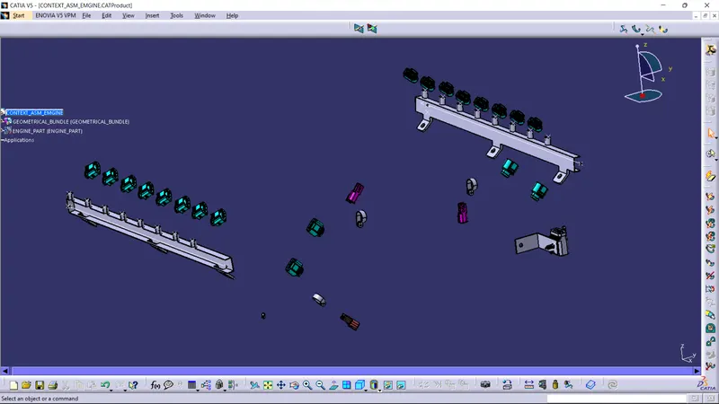
- After the geometrical bundle product is set then next switch to the ELECTRICAL HARNESS ASSEMBLY then select the define geometrical bundle option shown below,which defines your product as the harnessing assembly.

STEP:- 3.ROUTING:-
- Now that we have all the electrical parts positioned and the geometrical bundle defined,we are good to go for the routing.
- To create the routing we should work on ELECTRICAL HARNESS ASSEMBLY itself and select the multi-branchable option as shown in below diagram.
- When we activate this we will be automatically redirected to the ELECTRICAL HARNESS INSTALLATION workbench.

- This actives the the multibranchable features then the below pop up appears.
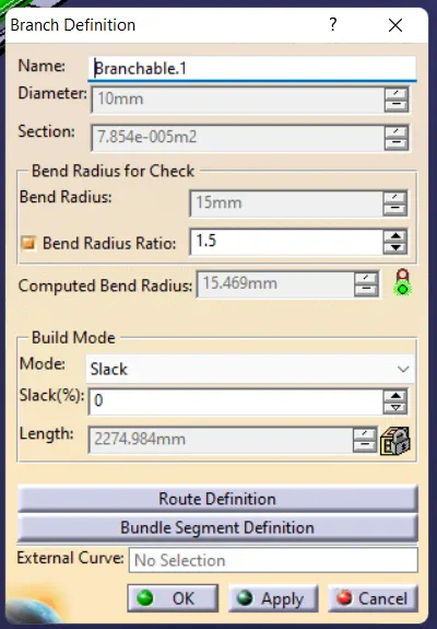
- Here we need to define the branch properties like bundle radius and bend radius
- The nominal bend radius can be manually set but we should set it to ratio of 1.5 as shown
- Next it shows the computed bend radius and shows a green color indication,which means our bundle segment can be doable without any errors.
- There is another feature called SLACK which is the lossness percentage in the bundle segment.Depending upon our requirement we we can set the slack percentage.Below that we also have the length option which shows the overall bundle segment length including the slack.
- After setting all this options enter the route defination dailog box opens, but we can use external curve option also if we want our bundle to be harnessed in our desired geometry.
- But mostly we select the route option and follow as shown.
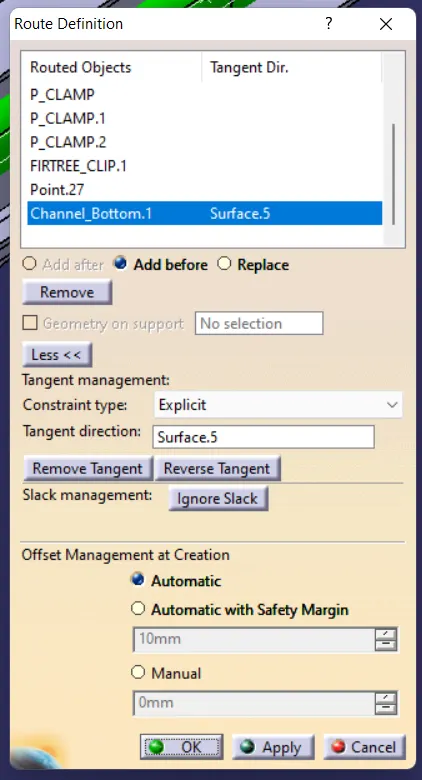
- In route defination we should start the routing by select the parts one by one as shown.
- We have 3 differnt options like add before , add after and replace which we use select the next part or before part or replace the part or point.
- After creating the routing click OK and we are reverted back to branch defination and again select OK,your bundle is generated.
- For adding a sub branch we should select ADD BRANCH POINT option which cuts the current branch,through which we can route another branchable.We can also delete the branch point and branches using the DELETE BRANCH POINT and DELETE SPECIAL options.
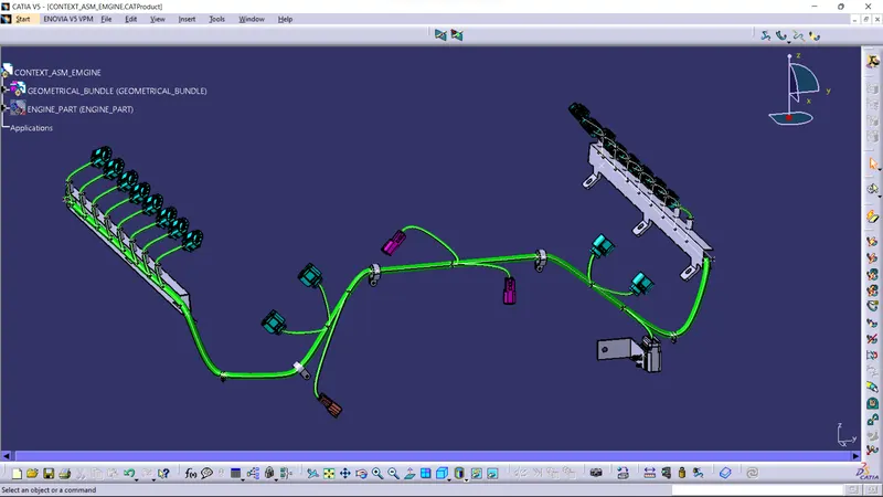
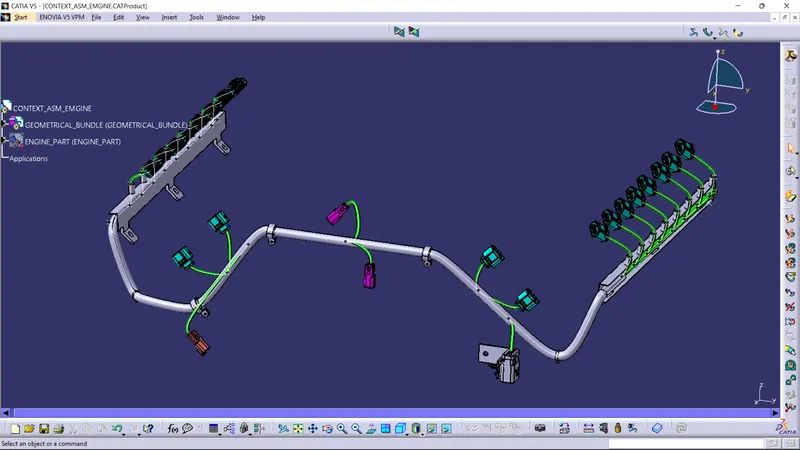
- Thus using all these options we can harness the routing as shown as below.
- We can add the cot tubes to branches which are directly getting exposed to the engine without guiding channels.
STEP:- 4.HARNESS FLATENNING:-
- Now that we have created the harness routing for the engine we have to create the flatenning of the model which is again converted to a 2d drawing.
- To ensure a smooth flatenning we should make sure all the branches are connected.
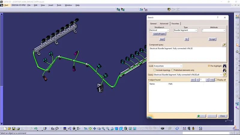
- We can check the bundle connectivity using the SEARCH option.
- Open the search option by clicking on the option or Ctrl + F is the shortcut for the search.
- Select the ADVANCED and in advanced select electrical in workenech,Bundle segment in Type, attribute can be TRUE OR FLASE.I have selected false.
- So, it will show if any bundles are not connected and list them out,here our bundles are fully connected thus,we can go for flatenning without expecting unnecessary errors.
- After checking the bundle segment connectivity switch to ELECTRICAL HARNESS FLATENNING.Three boxes will be there on top they are define Flatenning ,extract and flaten.
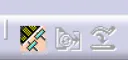
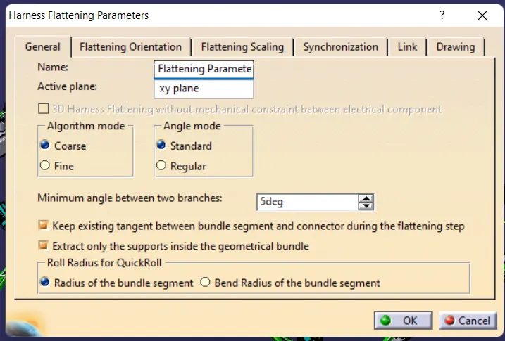
- select he flattening option and define the flattening parameters as shown
.
- Next select the extract option nex to the flattening and select our model ,The product and the multibranchable are saved as EHf parts as new bundles
- next step is to flatten the model by selecting the flatten option next to the extract and this pop up appears.
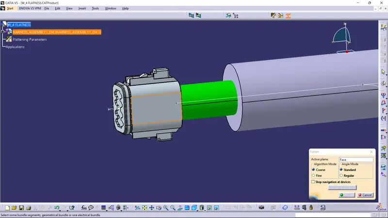
- You acn select any face as active to represent as the reference.And use the rotation tool and other tools to make in flatten as shown below down.
- When a flatten model is created it is automatically saved as EHf product and so in the flatten model every electrical product to appear we should save all the parts in single,for this fimction we can use the save management option and click propagate directory which will put all parts in the single folder.
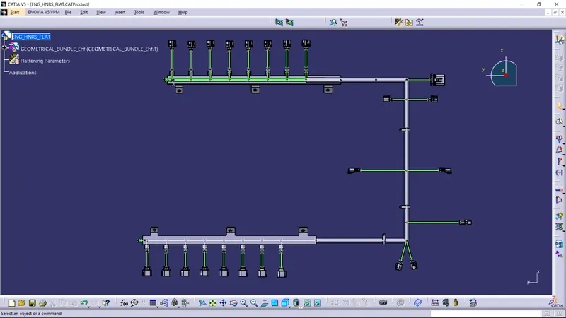
STEP:- 5.CREATING THE 2D DRAWING FROM THE HARNESS:-
- So that the flatten model is done next step is to create the drawing
- For effective drawing representation we should modify/ensure some specifications in the flattening parameters as shown below.
- The changes made here will reflect in the 2d drawing sheet.
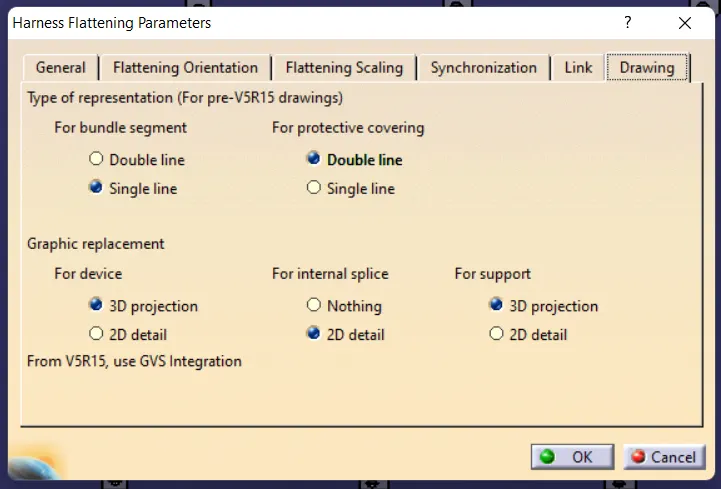
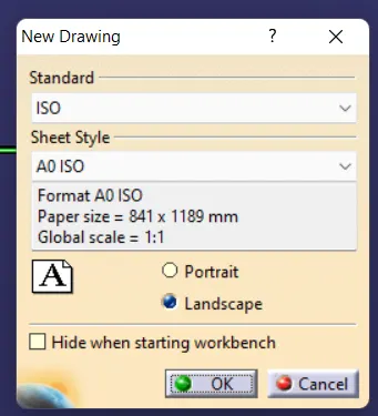
- After ensuring the desired options create new drawing document an select the type and size of the drawing sheet.
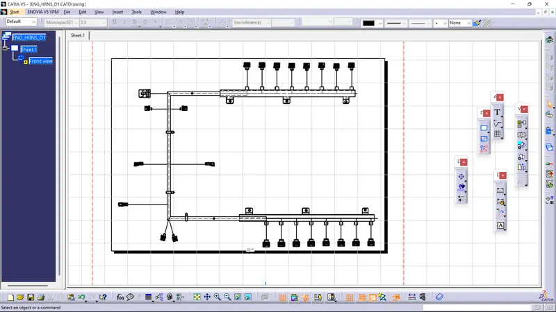
- Now rearrange the model to linear position so that it would fit into the sheet
- At first in the drawing the bundles wont appear,to make them appear double click and open properties in that select the wire frame and select ok,your bundle will appear.
- You can also enable the hidden line and centre lines for accurate repreaentation.
- After all the necessary dimensions are given and the drawing is validated,its forwarded to the manufacturing.
- Thus the wire harness routing for the given engine part is completed.
PLEASE FIND THE NECESSARY CATFILES IN THE BELOW UPLOADS