Project 1: Instrument Panel Substrate
Project – 1:
The Mesh and Mid Surface generation of the Instrument panel Substrate
Aim:
The Main Objective is to generate the mid surface and a proper mesh flow of the Instrument Panel Substrate.
Methodology:
The Steps of Construction to follow to get the good mesh flow and a better Design model using the given Quality Criteria.
- Performing Geometric Clean-up
- Creating Mid Surface
- Generating Mesh
- Checking for Errors
|
S. No |
Quality Criteria |
Value |
|
1 |
Target/Average length |
4 |
|
2 |
Minimum Length |
2 |
|
3 |
Maximum Length |
6 |
|
4 |
Aspect |
3 |
|
5 |
Warpage |
15 |
|
6 |
Skewness |
45 |
|
7 |
Jacobian |
0.7 |
|
8 |
Minimum Quad Angle |
45 |
|
9 |
Maximum Quad Angle |
135 |
|
10 |
Minimum Tria Angle |
30 |
|
11 |
Maximum Tria Angle |
120 |
|
12 |
Tria Percentage |
15 |
Theory:
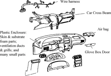
Instrumental Panel:
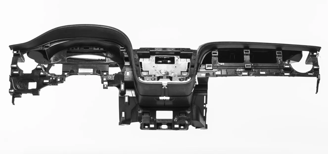
The Instrument panel is a sub-component of the car. The Instrument Panel is made of acrylonitrile-butadiene-styrene (ABS), ABS, or the polycarbonate alloys, polycarbonates, polypropylene, modified polyphenylene ether (PPE) and SMA (styrene-maleic anhydride) resins. These plastics allow for complex designs in items such as airbag housings, center stacks for instrument panels, and large, integrated instrument panel pieces. It is generally known as the dashboard.
Wholly integrated single-piece units can be manufactured from all-urethane and all-polypropylene resins. This results in a seamless instrument panel with greatly reduced NVH levels, molded-in color, and with significant cost savings for the manufacturer. Cost-effective post-consumer and in-plant recycling are also achievable.
An interior finish panel for a vehicle may include a panel substrate, at least two pieces of skin disposed over the panel substrate, and a foam layer. The panel substrate may include an inclined portion disposed between a base portion and at least one sealing surface. The at least two pieces of skin may include an upper skin and a lower skin joined together at a seam, wherein the seam may be at least partially disposed over the inclined portion. The seam may be sealed to a vertex of the inclined portion between the inclined portion and the sealing surface. The foam layer may be disposed between the at least two pieces of skin and the panel substrate. The foam layer may taper from the base portion towards the vertex of the inclined portion and terminate along the inclined portion before the vertex of the inclined portion.
Procedure:
- Opening the File:
- The file is downloaded initially. To open the file, follow the steps.
- Open ANSA >> Give Command Arguments >> OK >> Click Ctrl +O (for opening the file) >> Select the File>> Click Ok.
- On the Whole to describe the Opening of the file, click on the ANSA app, and wait for the launcher dialog box to appear.
- Once it appears, the dialog box contains the information called Additional ANSA command arguments are seen there will be an input box just below it. The argument has to be changed to “-performance_mode 3” (This means the performance of the app and it has Slower drawing and yet better quality.) then click ok to continue.
- The ANSA is now opened and then you can either open the file by using file option and open or Ctrl + O option.
- Geometric Check-up:
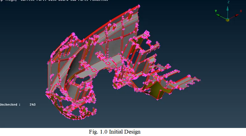
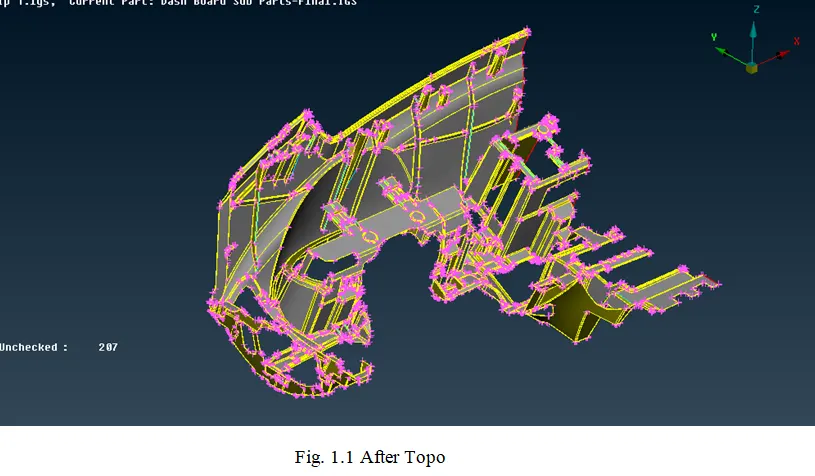
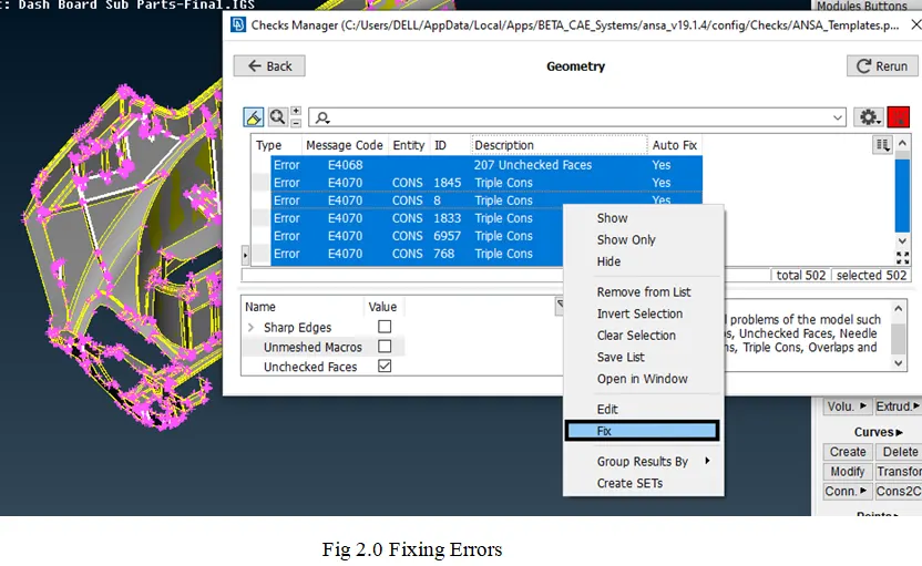
- This process is just used to check the topology of the model. In order to check the Topology follow the process as Tools>> Checks >> Geometry>> Execute.
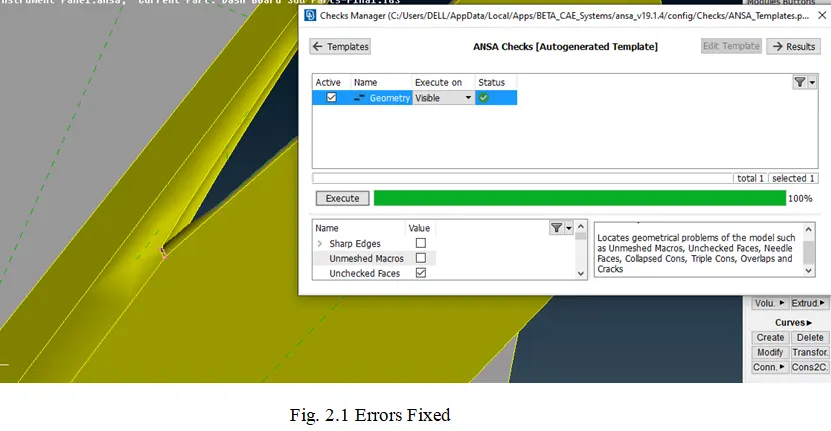
- Once executed, it might show a green bar stating there are no errors in the geometry or it may show the dialog box showing the errors present in it.
- These errors can be fixed either by going on with them individually or once Right-clicked on the mouse an additional list pops- up.
- Fix option will be present in that pop-up when it is clicked the errors which can be fixed are executed and it might contain only a few errors which should be fixed manually and if no errors are present then it will show the green bar stating executed.
- The process is called geometric clean- up. It can be done either completely or part-wise of the parent geometry.
- Giving the PID:
- The PID is used to create a property of the particular model parts or the total model. In order to create a new PID or to check the existing PID’s.
- Click Lists >> Properties.
- You can see the Properties which are created before. In order to create a new PID, right-click on the dialog box, the drop-down appears.
- Click New >> PSHELL>> PSHELL.
- Then a New PID is created. In order to assign a part to the PID. Select the element needed to be assigned and do the middle click on the mouse to confirm.
- Creating the Mid Surface:
- For Main Part:
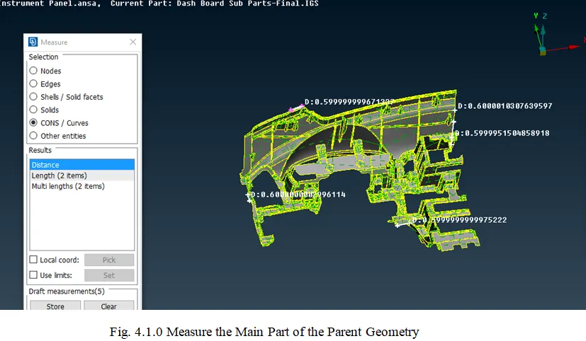
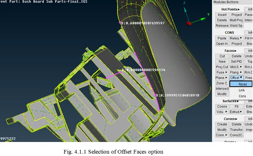
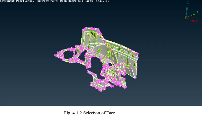
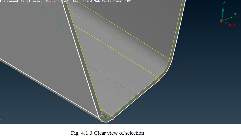
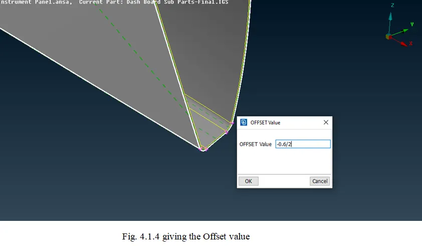
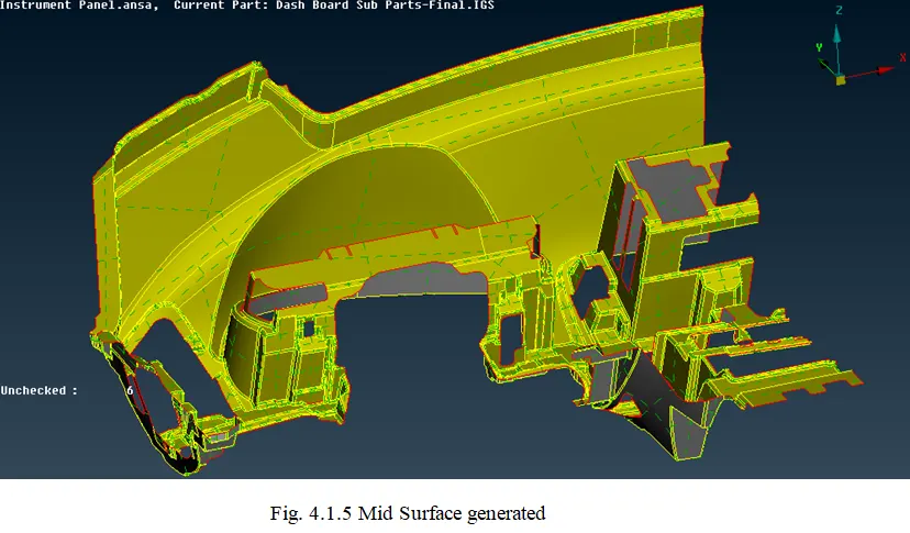
- The Main Part has a similar thickness therefore the Offset Method can be used. To create mid-surface, the Steps are as follows
- In Topo Deck, Faces Module, Click Offset >> Faces >> Select the Face >> Give the Values >> Click OK
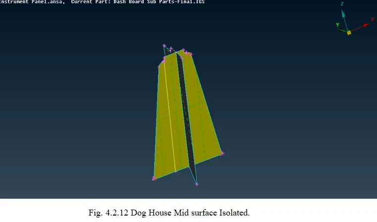
- For Dog Houses:
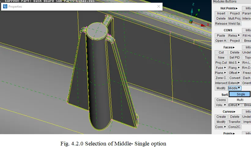
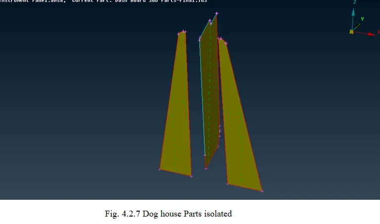
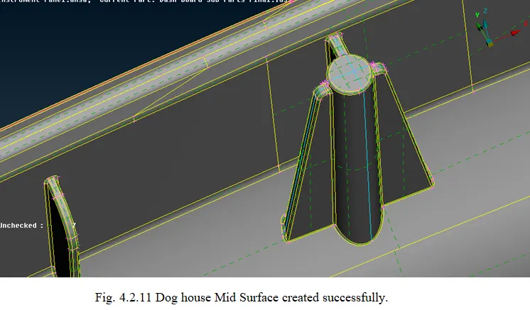
- The Dog House parts are generally used for assembly fixation. For Dog House mid-surface, the following steps are followed
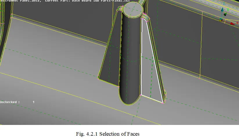
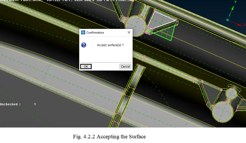
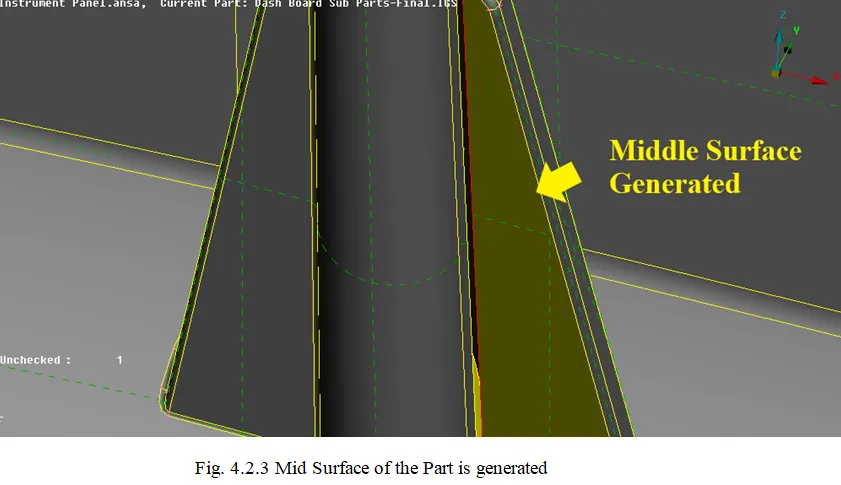
- In Topo Deck, Faces Modules, Click Middle >> Single >> Select the faces.
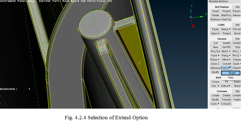
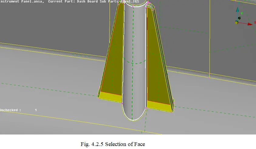
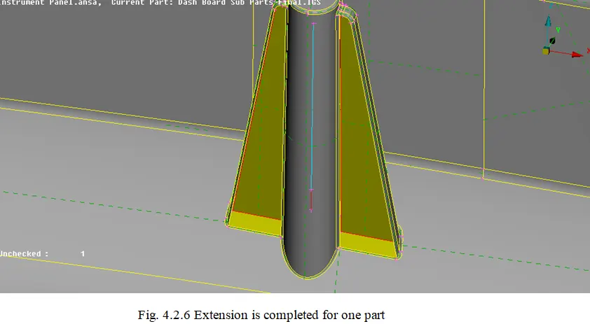
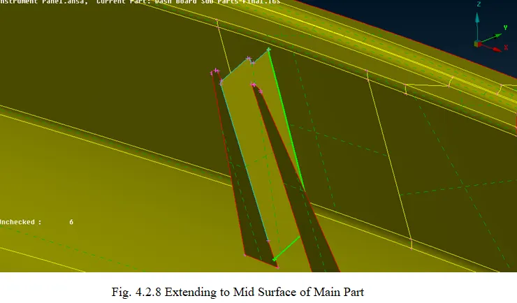
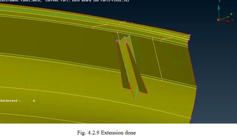
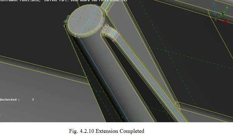
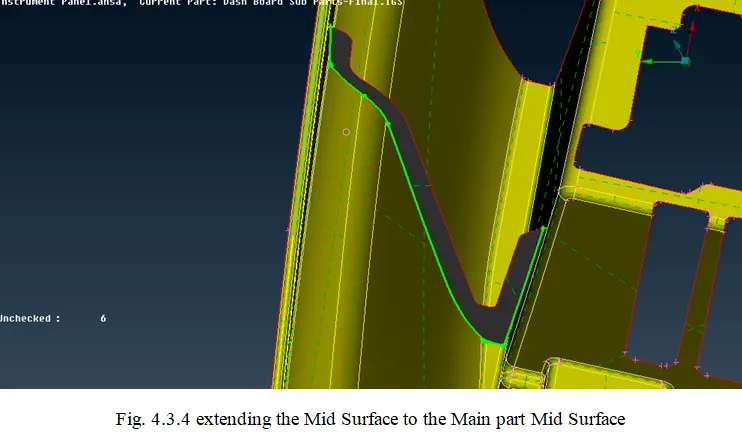
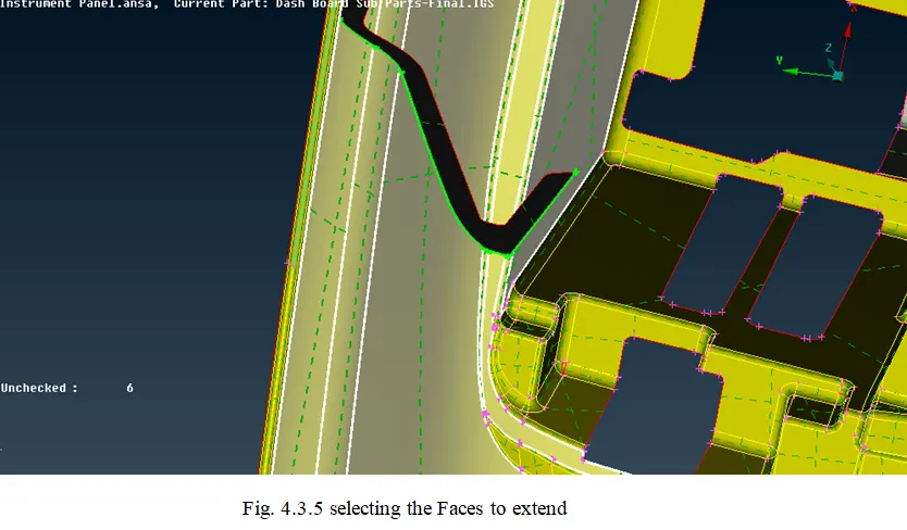
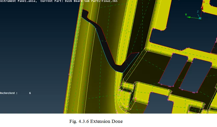
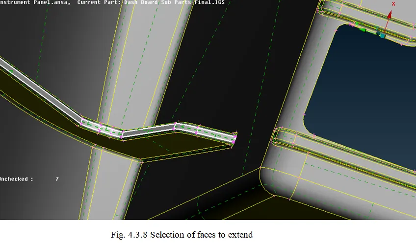
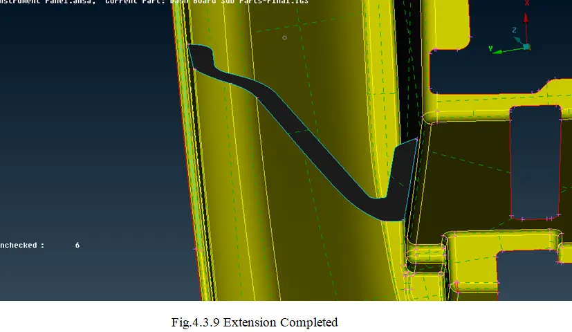
- The mid surface is generated then the model is needed to be similar to that of the parent geometry. To get the mid surface as the parent geometry, the Extend tool is used.
- In Topo Deck, Faces Modules, Click Extend >> Select the edge >> Select the face till the extension needs to be done.
- For Ribs:
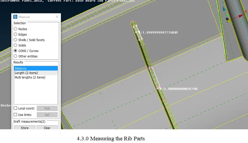
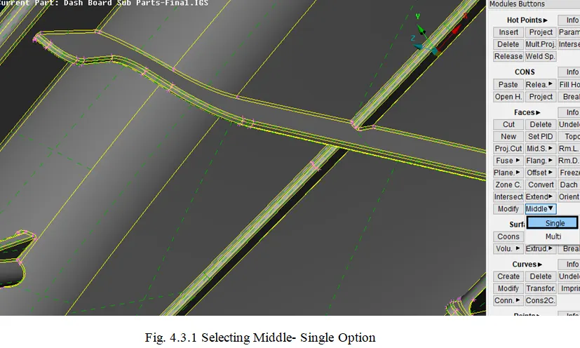
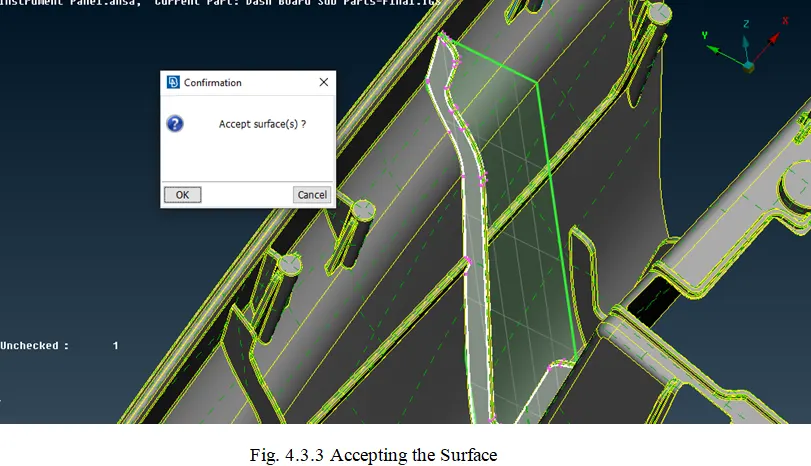
- The mid surface for the Ribs is similar to the Doghouses. The mid surface is either taken by using the Offset method or by the Middle as explained above.
- In Topo Deck, Faces Modules, Click Middle >> Single >> Select the faces.
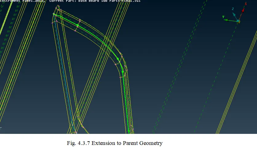
- After creating the mid surface the extending is done to ensure that the mid surface and the parent geometry are of the same length.
- In Topo Deck, Faces Modules, Click Extend >> Select the edge >> Select the face till the extension needs to be done.

- Generating the Mesh:
- Creating the Mesh:
- To create a mesh for any model, select mesh Click Modules >> Mesh.
- Once the mesh module buttons are opened and seen. Initially for outer hood mesh can be created by using tools like Hot Points, Perimeters, Mesh Generation, Shell Mesh, Elements.
- Select the entire mesh and confirm it, once it is done a dialog box appears stating the length as 5 in both perimeters and macros simultaneously.
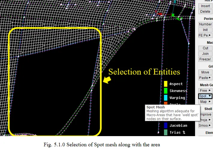
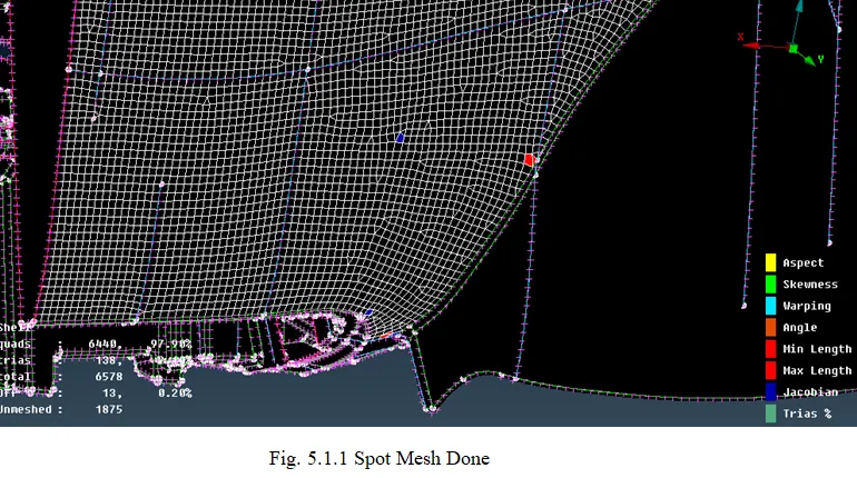
- In mesh generation, Select Spot and select the element to mesh and confirm it.
- Click Spot (in Mesh Generation) >> Select the Entity to mesh.
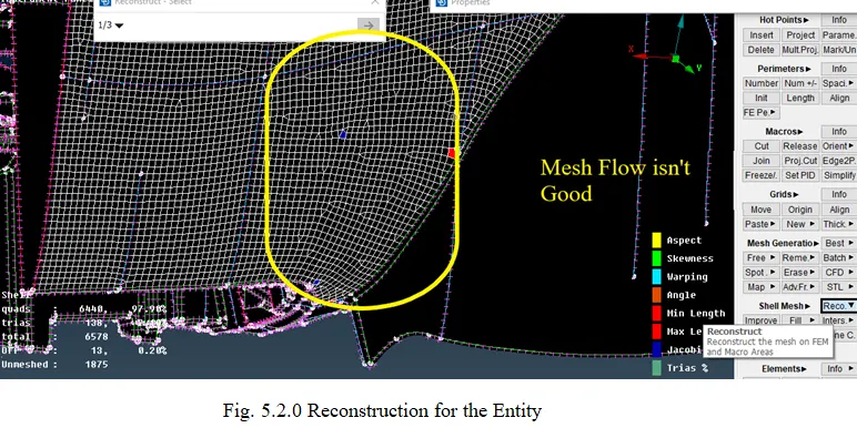
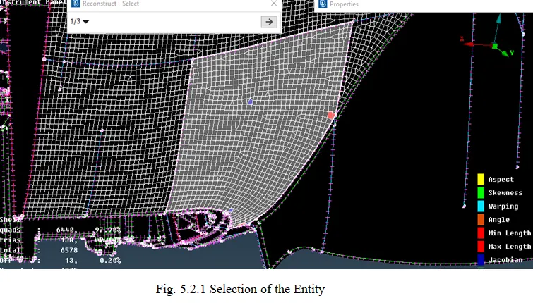
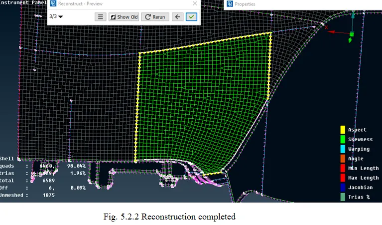
- Reconstructing the Mesh:
- The Mesh might not be as perfect as it should be and contains many Off elements (Which doesn’t meet the Quality Criteria) in order to remove the off elements or to reduce them Reconstruct option is used.
- It can be seen in Shell Mesh >> Reconstruct.
- Making a Smooth Mesh Flow:
- Once the Off elements are fixed or reduced the mesh should be made softer.
- To make the mesh softer Smooth option is used. It can be seen in Shell Mesh >> Smooth.
Errors:
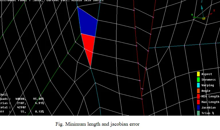
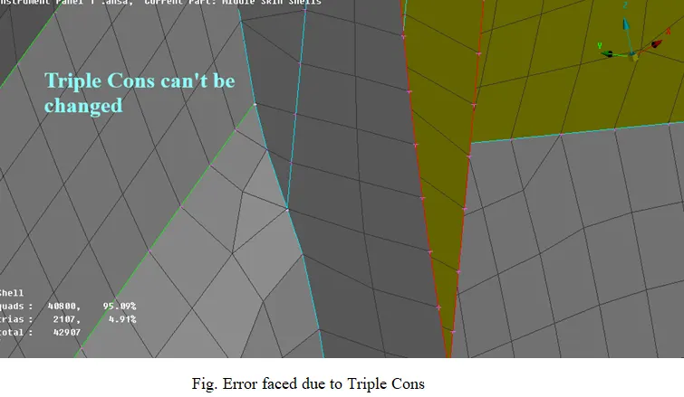
The Errors which are found while performing the mesh are related to the Triple cons and those are generally the minimum length errors.
Results:
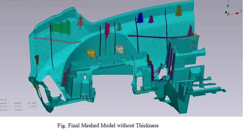
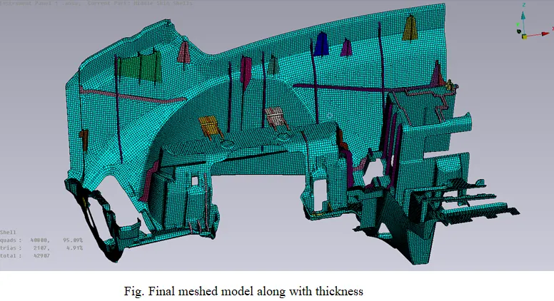
The mid surface is created with a proper Mesh flow and the thickness is added.
Learning Outcomes:
The outcomes learned while working the model are as follows
- To perform Geometric Clean-up
- Giving the PID to the surfaces
- To generate the mesh
- Reducing the errors.
- Creating the proper mesh flow.
Bibliography:
Instrumental Panel: Substrates for vehicle instrument panel
Google Drive Link: Instrument Panel Meshed Model