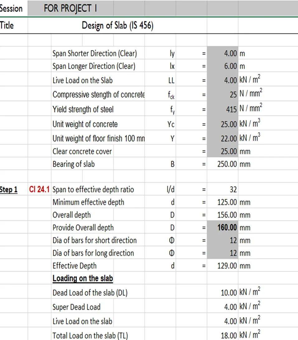
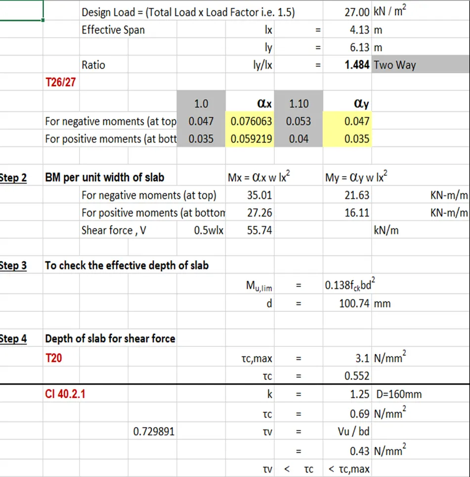
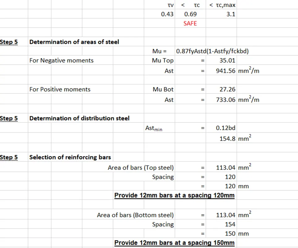
Project 1
1. I. DESIGN BASIS REPORT
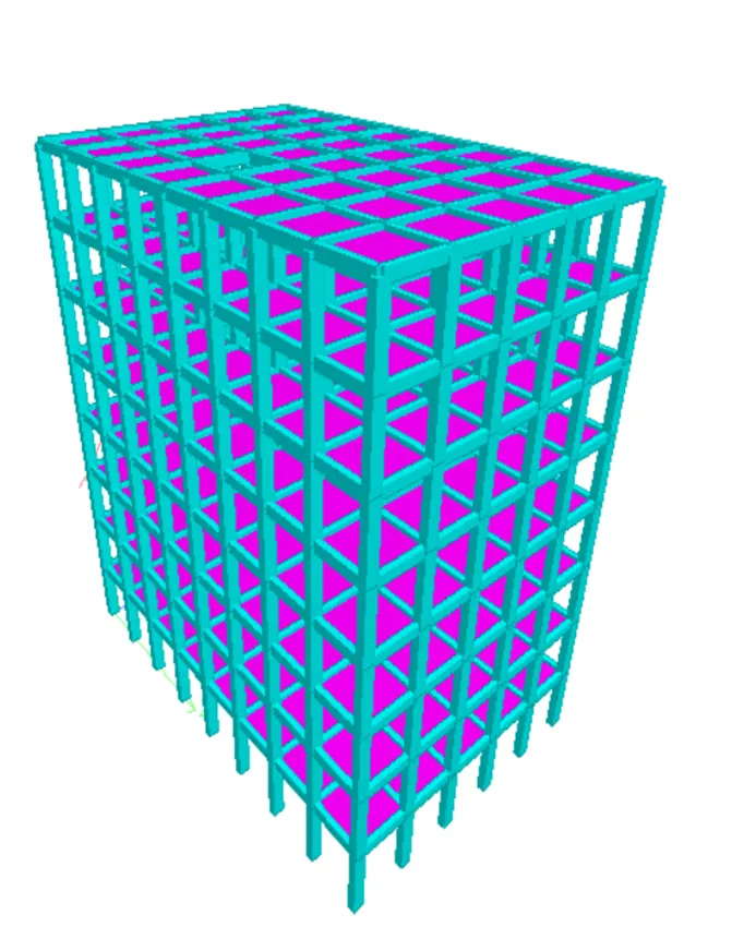
3D ELEVATION OF G + 6 + ROOF
1. GENERAL CHARACTERISTICS OF PROJECT
Project Description
Project : G+6 + Roof – 8 story
Location : Bangalore
Use : Residential
Project Information Data:
Plan dimension: Length - 16.00 m
Breadth - 25.00 m
Story height - 3.5m
Soil type : Hard soil
Safe bearing capacity : 180 KN/m2
Maximum slab thickness : 150mm
The building/structure is RCC framed structure with Steel(TMT) Fe 500 (Yield stress - 500 ) and Cement OPC Gr - 43
2. CODE REFERENCES:
|
IS Code Ref |
Description |
|
IS 875(Part 1): 1987 |
Dead Loads - Unit Weight of Building Material and stored material |
|
IS 875(Part 2) :1987 |
Imposed Loads |
|
IS 875(Part 3) :1987 |
Wind Loads |
Design for Earthquake Resistance:
|
Description |
|
|
IS 1893:2002 |
Criteria for earthquake resistance design of structures |
|
IS 13920: 1993 |
Ductile Detailing of Reinforced Concrete Structures Subjected to Seismic Forces – Code of practices |
Design of plain and RCC Concrete Element:
|
IS Code Ref |
Description |
|
IS 456: 2000 |
Plain and Reinforced Concrete - Code of practice |
|
SP 34 |
Handbook on Concrete Reinforcement &Detailing |
3. LOADING AND FORCES:
Loads and forces used for design shall be as defined in IS 875, and is specified below.
The following type of loads and forces shall be considered.
· Dead load (DL)
Dead load is the load of the structure itself.
· Following is the unit weight of major construction materials. · Reinforced Cement Concrete 25.0 KN/m3
· Plain Cement Concrete 24.0 KN/ m3
· Structural Steel 78.5 KN/ m3
· Saturated soil density 19.5 KN/ m3
· Masonry walls will be with CC hollow blocks of max density 18 KN/m3.
· Live load (LL)
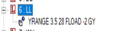
Live load for building and structure shall be in accordance with IS875 part 2 unless otherwise specified – 4 KN/M2
· Wind load (WL)
· Wind load to be applied for structures shall be in accordance with IS875 part 3, and noted below.
· Basic wind speed, Vb, Shall be 55m/sec
· Risk coefficient ‘K1’ shall be equal to 1.0.
· Terrain Height & Structure Height factor ‘K2’ shall be obtained form table 2 IS 875 part
· Topographic factor K3 = 1.0
Design wind speed Vz at any height zin m/sec
Vz = Vb x K1 x K2 x K3
Design wind pressure Pz at any height zin N/m2
Pz = 0.6 Vz2 However as either of wind or seismic forces has to be considered at a time, wind loads will not be considered for the design, as they don’t govern.
· Earthquake load (EQ)
Seismic loads to be applied for structures shall be in accordance with the applicable provision of the IS 1893, 2016 and noted below.
· Seismic Zone Factor, Z, shall be 0.36
· Importance factor I, shall be 1.5
· Soil type=Medium
· Response reduction factor shall be 5 for RCC structures (SMRF).
· Average response acceleration factor Ah = Z/2 x I/R x Sa/g
E = Ah x W Where ‘W’ is seismic weight of structure with appropriate live load. Time period in accordance with IS code of infill wall condition and non-infill condition to be calculated separately. Average of the two values to be considered for design as the frames of the towers are semi in filled. Ductility provision in detailing of RCC structures shall be considered judiciously based on IS: 13920- 2016 for Lateral force resisting elements of the structure.
· COMBINATION OF LOADS
Load Combination for Concrete Structures Concrete structural members shall be designed to have, at all sections, a calculated strength necessary to carry the following factored loads and forces as per table 18 of IS 456.
( Generated by Software Staad Pro – DL and LL combinations)
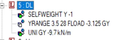
· Dead Load (DL) Dead load is the load of the structure itself.
Following are the unit weight of major construction materials. · Reinforced Cement Concrete 25.0 kN/m3 · Plain Cement Concrete 24.0 kN/ m3 · Structural Steel 78.5 kN/ m3.
· CONCRETE STRUCTURES AND FOUNDATIONS
Design and calculation All concrete design shall conform to IS456-2000, unless noted otherwise. The detailing of concrete reinforcement shall be in accordance with the requirements given in IS13920-2016.
DESIGN PARAMETERS RCC structures shall be designed based on limit state method of design as given in IS: 456-2000 & ductility provision in detailing of RCC structures shall be considered judiciously based on IS: 13920- 2016 for Lateral force resisting elements or the structure.
The following parameters shall be used: RCC GRADE: Minimum M30 for all works, or as per drawings in accordance with clause 6.0 (Table 5) of IS 456-2000 for all. REINFT STEEL GRADE 500 N/sqmm: High yield strength deformed bars conforming to IS 1786 with minimum yield strength of 500N/Sqmm have been considered.
CLEAR COVERS: (clause 26.4 of IS 456:2000 Table 6)
Foundations - 50mm
Columns - 40mm
Beams/Walls - 25mm
Slabs - 20mm.
I. STRUCTURAL MODEL .
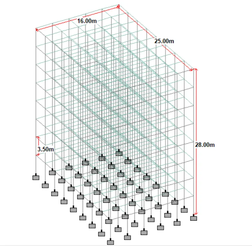
I.
DL III. (Dead load):
LL (Live Load):
WL (Wind load):
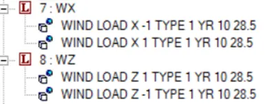
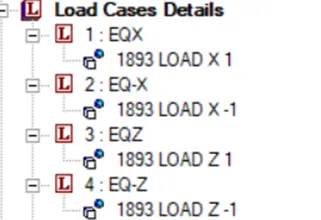
EQ(Earth quake load on X,Z).
IV.