Project 1
- Aim:- To Model and Desogn a Proposed Coil Centre in Chennai using STAAD Pro.
- Procedure:-
- Step 1:-
- First we have model and design a Main Frame with Lean (Grid 2).
- Open STAAD Pro Software, and create a new file.
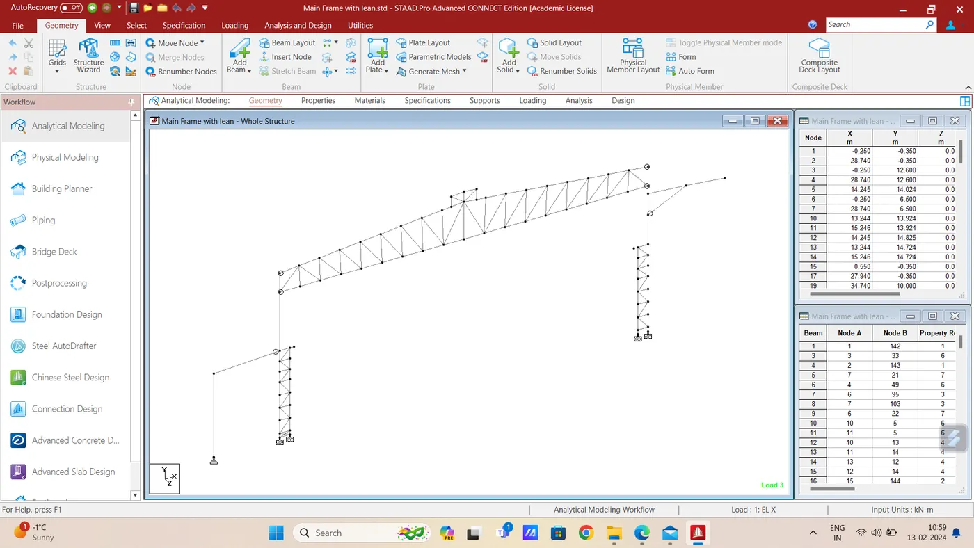
- In Geometry Tab, Create a Main frame model using Nodes, Beams and Mirror commands as shown below.
- Step 2:-
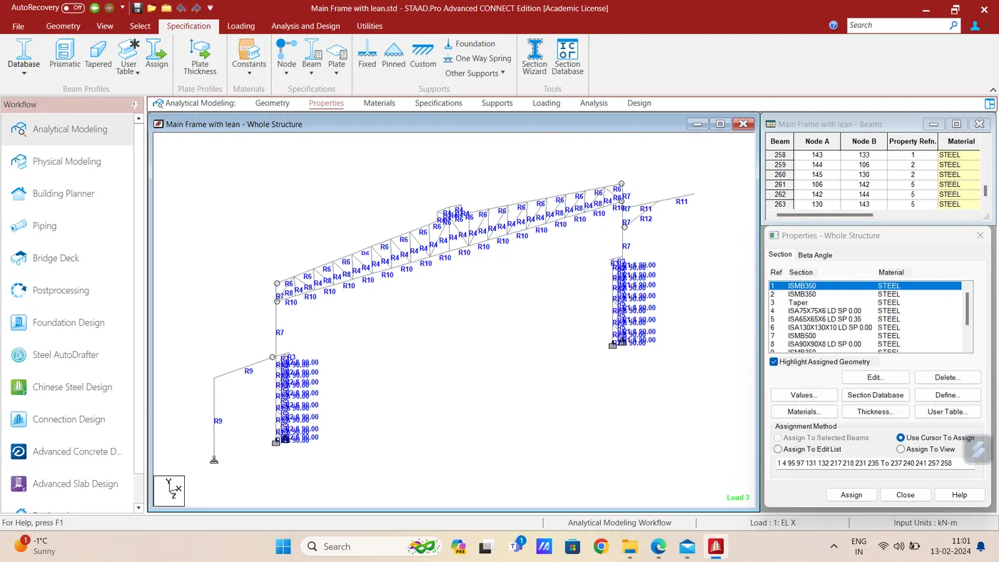
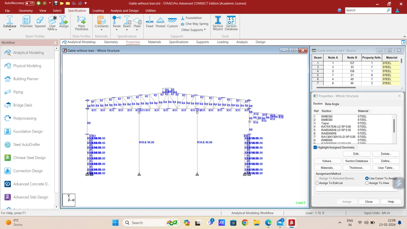
- Select Properties Tab, and create a Sections in Section Database.
- And Assign the sections to the members as shown below.
- Step 3:-
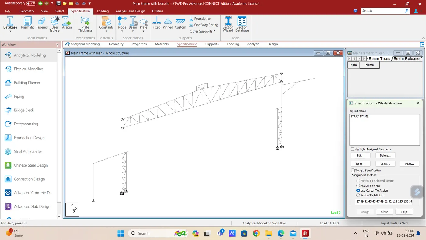
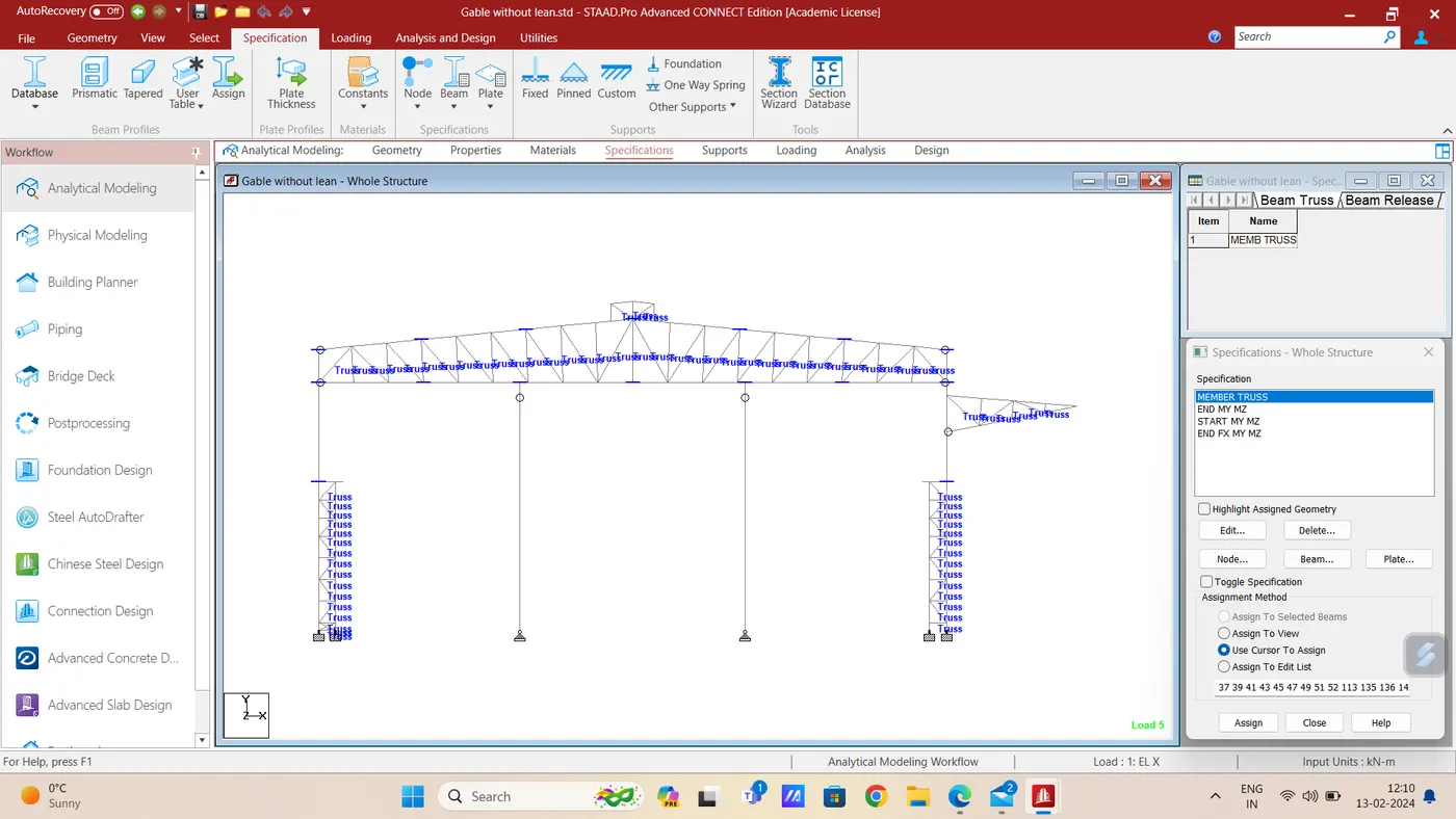
- In Specification tab, create and assign the Moment Release to the required beams.
- Step 4:-
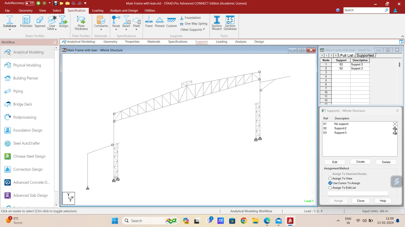
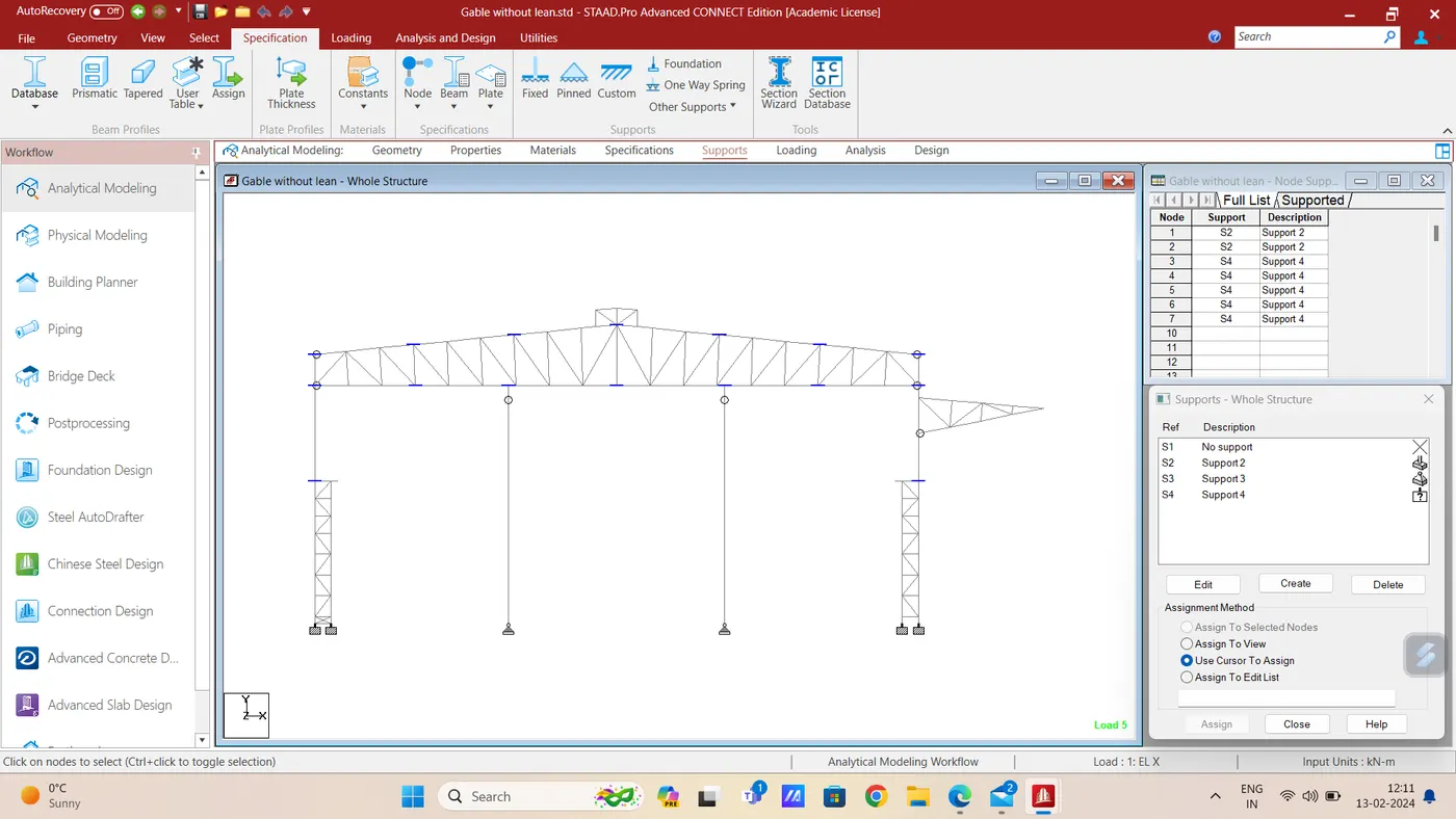
- Select Support Tab, create Fixed and Pinned Supports.
- Then assign the Fixed support to Main Frame column and Pinned support Lean column
- Step 5:-
- Then Prepare inputs for loads.
- Dead Load Calculation:
- Given data:-
- Dead Load = 0.14 kN/m2 (for main portion without false ceiling)
- Collateral Load = 0.15 kN/m2
- Total Dead load = 0.14 + 0.15 kN/m2 = 0.29 kN/m2 (for roof extension)
- Let’s Assume Purlin and Girt weight as 8.77 kg/m
- Bay Spacing = 10m
- Therefore,
- Purlin Load on Roof = 8.77 x 10/2 = 43.85 kg = 0.44 kN
- Purlins on Wall:
- Total number of Purlin in Near Side wall = 5
- Total number of Purlin in Near Side wall (Crane supported column) = 3
- Total number of Purlin in Far Side wall = 2
- Therefore,
- Purlin Load on NSW = 5 x 8.77 / 6.1 = 7.2 kg/m2 = 0.072 kN/m2
- Purlin Load on NSW = 3 x 8.77 / 3.5 = 7.52 kg/m2 = 0.075 kN/m2
- Purlin Load on FSW = 2 x 8.77 / 2.1 =8.35 kg/m2 = 0.0835 kN/m2
- Total DL over truss = (0.14) x 10 = 1.4 kN/m
- Total DL over Cantilever portion = (0.29) x 10 = 2.9 kN/m
- Total Dead load on NSW = (0.14 + 0.072) x 10 = 2.12 (above crane supporting column)
- Total Dead load on NSW = (0.14 + 0.075) x 5 = 1.075 (in crane supporting column)
- Total Dead load on FSW = (0.14 + 0.0835) x 10 = 2.24 (on wall above cantilever)
- Gantry weight = 158.24 kg/m
- Rail weight = 53 kg/m
- Weight on bracket = 211 x 5 = 1056 kg = 1056 kN
- Lattice tie of 200 kg is between the column
- Load on column = 200 /2 = 100 kg = 1kN as joint load
- Totally 9 Purlins
- Load on column due to Purlins = (9 x 8.87 /11.1) = 7.2 kg/m2 = 0.072 kN/m2
- Load on column = 0.072 + 0.14 = 0.212 kN/m2 = 0.212 x 10 = 2.12 kN/m
- Live Load Calculation:
- Given data:-
- Live Load = 0.75 kN/m2
- Live Load on Rafter = 0.75 x 10 = 7.5 kN/m
- Wind Load Calculation as per IS 875 Part III:
- Given data:-
- Wind speed = 50m/s
- K1 = 1; K2 = 0.94 (terrain category 3); K3 = 1; K4 = 1.15 (cyclone zone)
- Ka = 1; Kd = 0.9; Kc = 0.9
- Basic wind speed Vb = 50 m/s ( For Chennai as per IS 475 part-3 Fig. 1)
- Design wind speed Vz = Vb x K1 x K2 x K3 x K4
- Therefore Vz = 1.0 x 0.94 x 1.0 x 1.15 x 50 = 54.05 m/s
- Wind pressure Pz = 0.6 (Vz)2
- Where,
- Pz = wind pressure at height z in N/m2
- Vz = design wind pressure at height z in m/s
- Therefore
- Pz = 0.6 x (54.05)2 = 1.752 kN/m2
- Design wind pressure Pd = Kd x Ka x Kc x Pz
- Therefore
- Pd = 1.0 x 0.9 x 0.9 x 1.752 = 1.419 kN/m2
- Wind load acting in a direction normal to the individual structural element or cladding unit
- F = (Cpe – Cpi) x A x Pd
- Where,
- Cpi = internal pressure coefficient
- Cpi = +0.5 and -0.5 for opening of 15% of wall area i.e. medium permeability (Clause 7.3.2.2 of IS :475, part 3)
- External pressure coefficient:
- L = 140 m; w = 41 m; h = 11.7 m
- h/w = 11.7 / 41 = 0.29
- l/w = 140 / 41 = 3.41
- Thus as per table 5 of clause 7.3.3.1 of IS:475, Part 3
- For h/w < 1/2 and 3/2 ≤ l/w < 4
|
Wind angle Ɵ |
Cpe For Wall Surface |
|||
|
Wall A |
Wall B |
Wall C |
Wall D |
|
|
0° |
+0.7 |
-0.25 |
-0.6 |
-0.6 |
|
90° |
-0.5 |
-0.5 |
+0.7 |
-0.1 |
- For h/w < 1/2 and Roof Angle as 5°
|
Cpe For Roof Surface
|
Wind angle Ɵ |
|||
|
0° |
90° |
|||
|
EF |
GH |
EG |
FH |
|
|
-0.5 |
-0.5 |
+0.7 |
-0.1 |
|
- For Cantilever portion alone reduction due to area averaging.
- Ka = 0.85 (since tributary area is 10 x 6 = 60 m2)
- Thus kd x ka x kc < 0.7 Taken as 0.7 (upper limit)
- Pd = 0.7 x 1752.8 = 1.23 kN/m2
|
Wall Coeficient |
Pd = |
1.42 |
MF Spacing |
10 m |
EF Spacing |
10.40 m |
||||||
|
Cpe for surface |
Wind Angle 0° |
Wind Angle 90° |
Cpi+ |
Cpi- |
Cpe - Cpi (0+Cpi) |
Cpe - Cpi (0-Cpi) |
Cpe - Cpi (90+Cpi) |
Cpe - Cpi (90-Cpi) |
pd (0 + Cpi) |
pd (0 - Cpi) |
pd (90 + Cpi) |
pd (90 - Cpi) |
|
A |
0.7 |
-0.5 |
0.5 |
-0.5 |
0.2 |
1.2 |
-1 |
0 |
0.284 |
1.704 |
-1.42 |
0 |
|
B |
-0.25 |
-0.5 |
0.5 |
-0.5 |
-0.75 |
0.25 |
-1 |
0 |
-1.065 |
0.355 |
-1.42 |
0 |
|
C |
-0.6 |
0.7 |
0.5 |
-0.5 |
-1.1 |
-0.1 |
0.2 |
1.2 |
-1.562 |
-0.142 |
0.284 |
1.704 |
|
D |
-0.6 |
-0.1 |
0.5 |
-0.5 |
-1.1 |
-0.1 |
-0.6 |
0.4 |
-1.562 |
-0.142 |
-0.852 |
0.568 |
|
Wall Coeficient |
|||||
|
Cpe for surface |
Spacing |
pd (0 + Cpi) in kN/m |
pd (0 - Cpi) kN/m |
pd (90 + Cpi) in kN/m |
pd (90 - Cpi) kN/m |
|
A |
10 |
2.84 |
17 |
-14 |
0 |
|
B |
10 |
-10.65 |
3.55 |
-14 |
0 |
|
C |
10.4 |
-16.2448 |
-1.5 |
3 |
17.7216 |
|
D |
10.4 |
-16.2448 |
-1.5 |
-8.9 |
5.9072 |
- Crane Load Calculation:
- Capacity = 30MT
- Selfweight = 35MT
- Vertical impact = 1.25
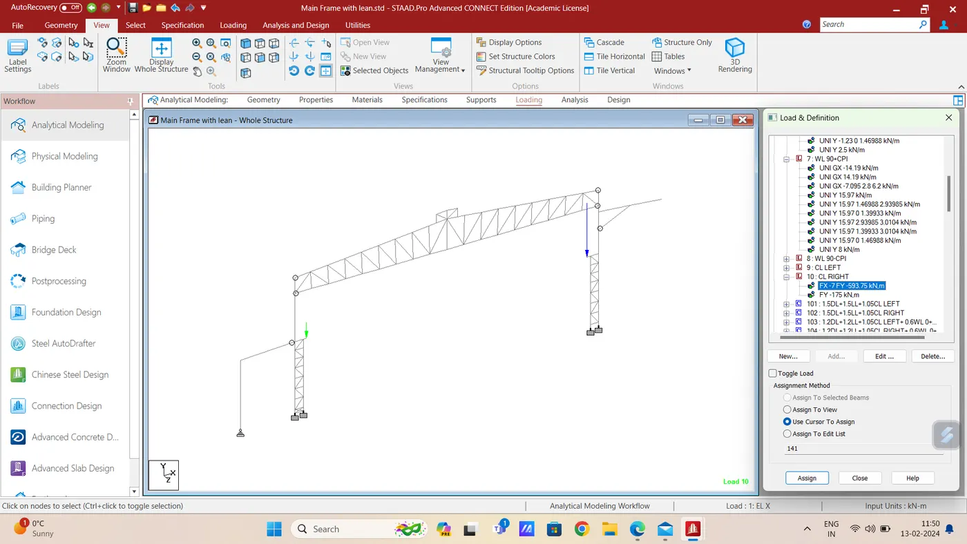
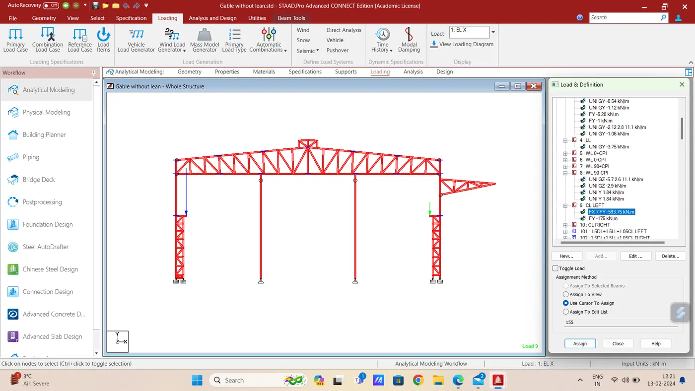
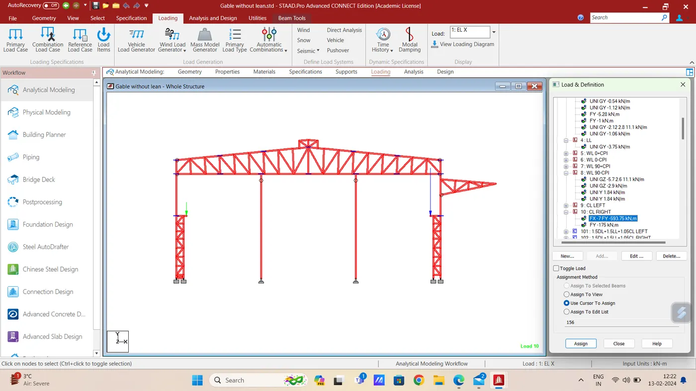
- Load for Left end = 1.25 (300 + 175) = 593.75 kN
- Lateral Impact = 0.2 x Crane Weight = 0.2 x 35 = 7 kN
- Half of the Selfweight of Crane acting on the other side.
- Step 6:-
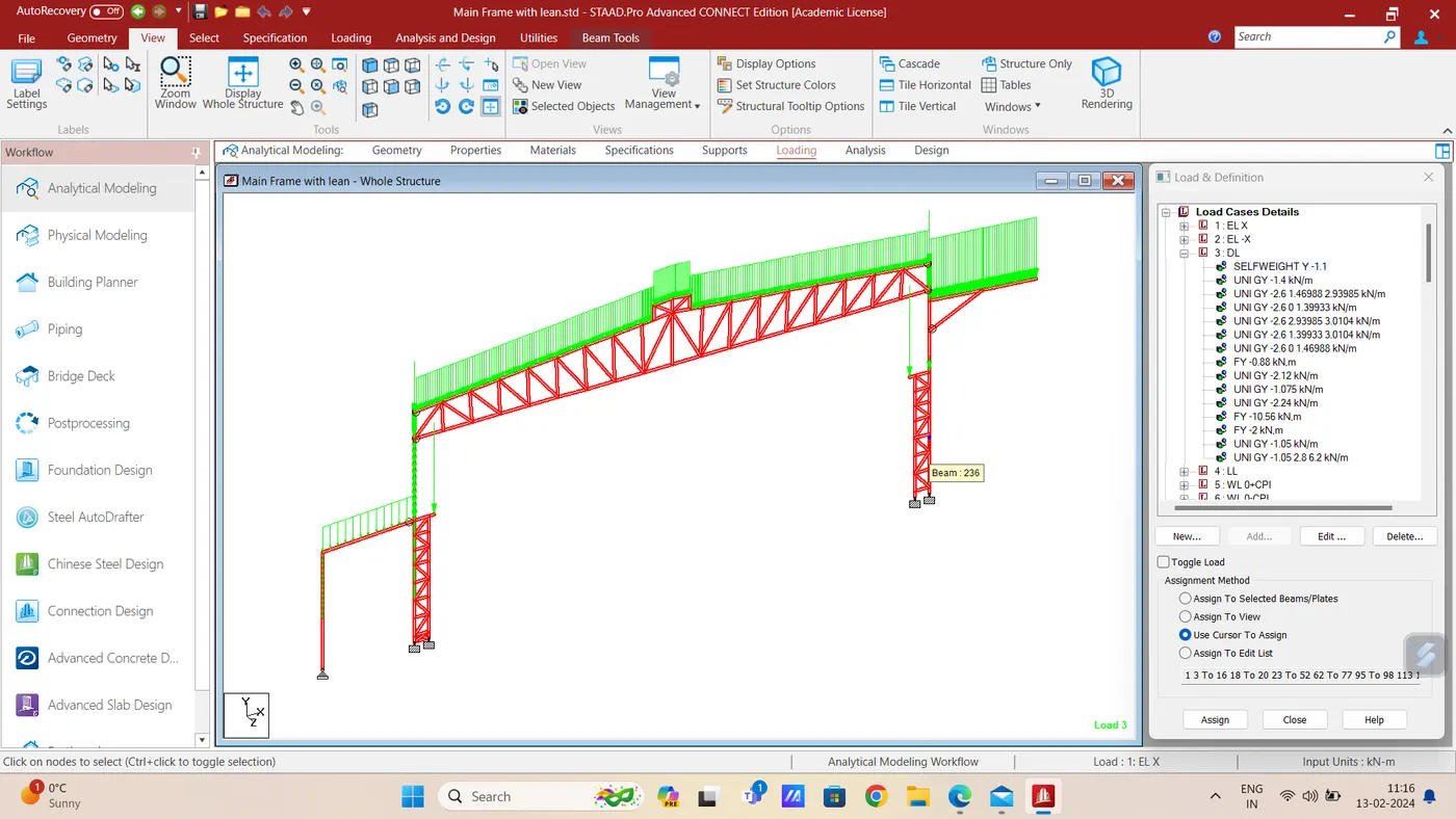
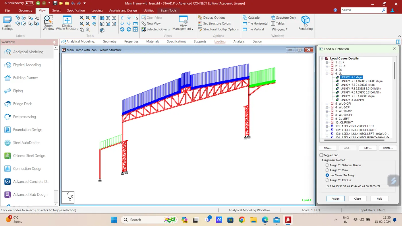
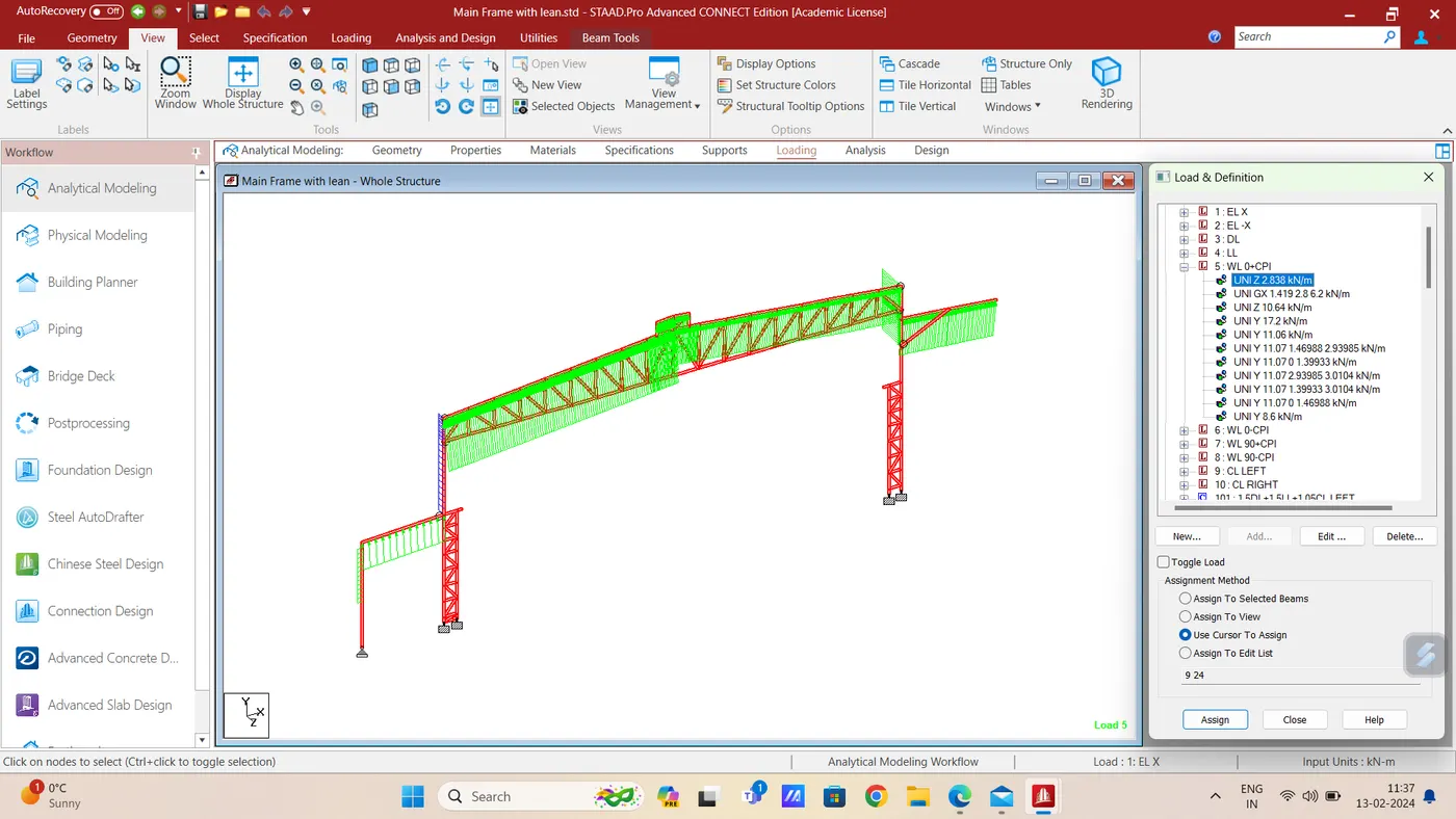
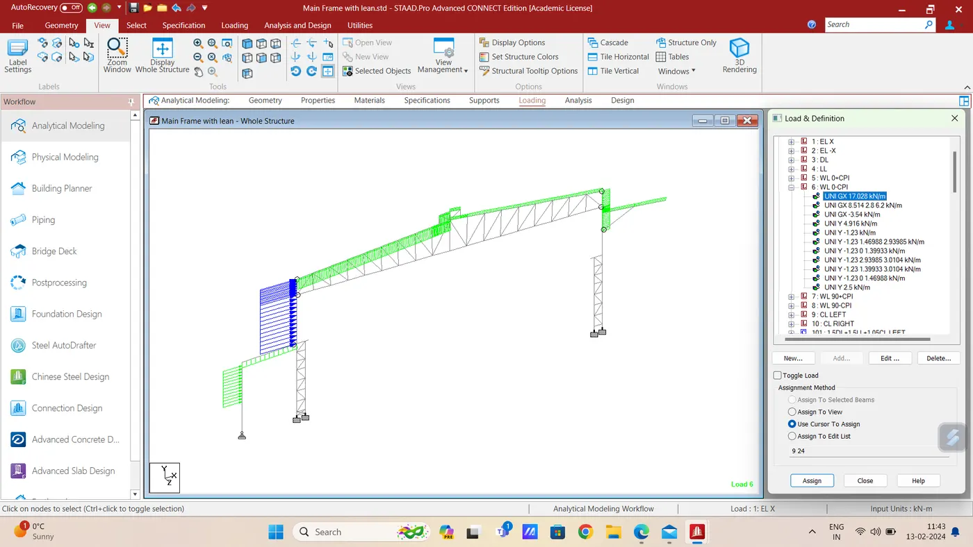
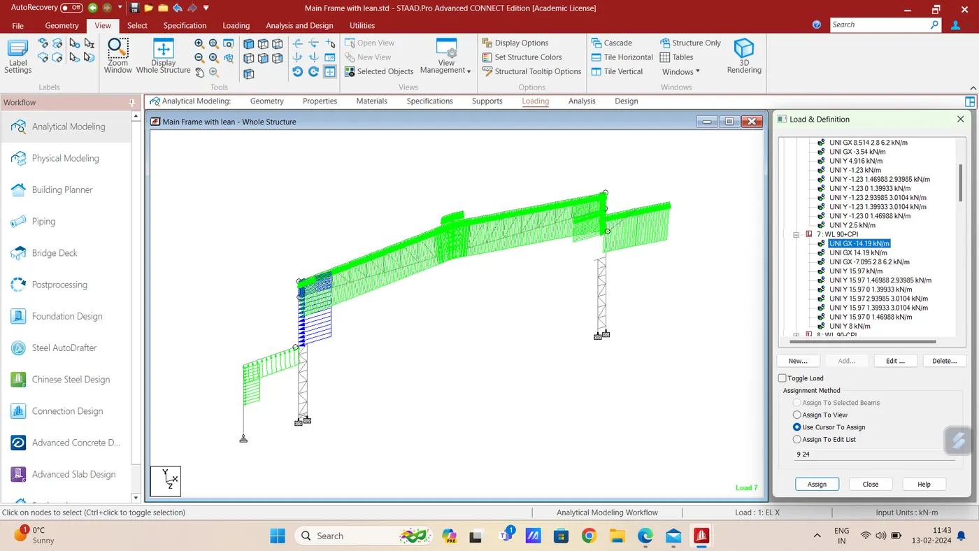
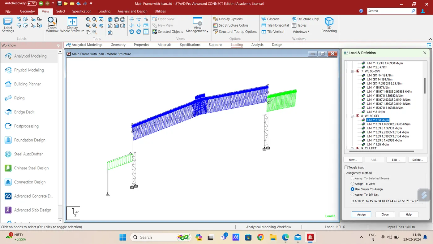
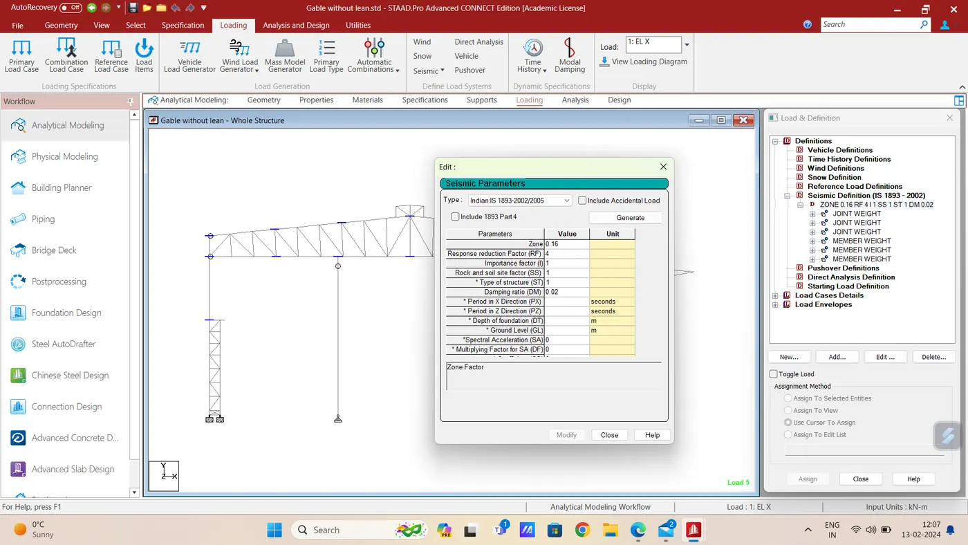
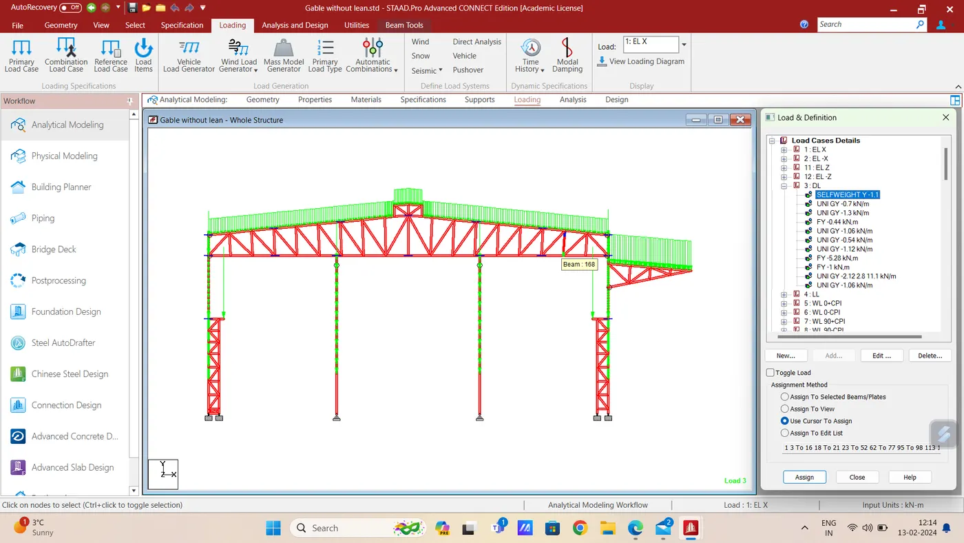
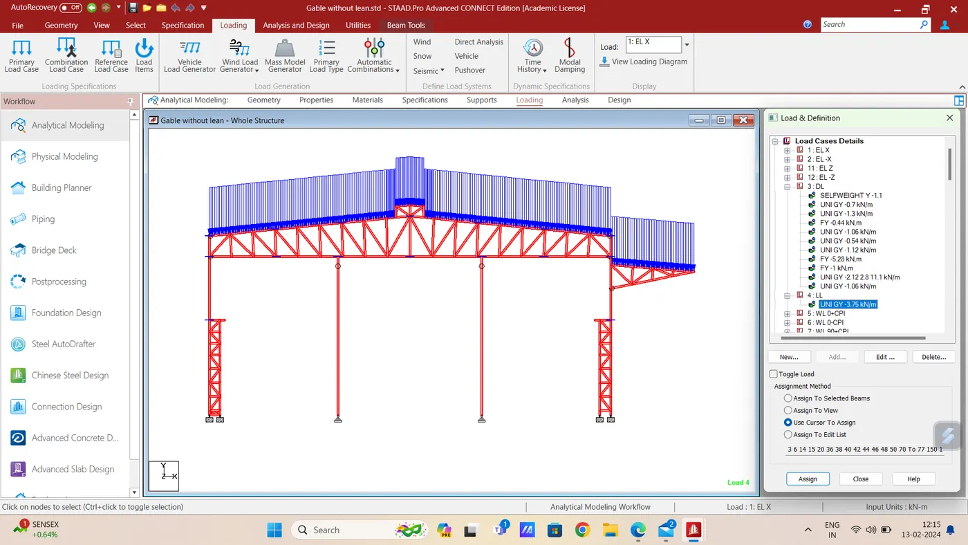
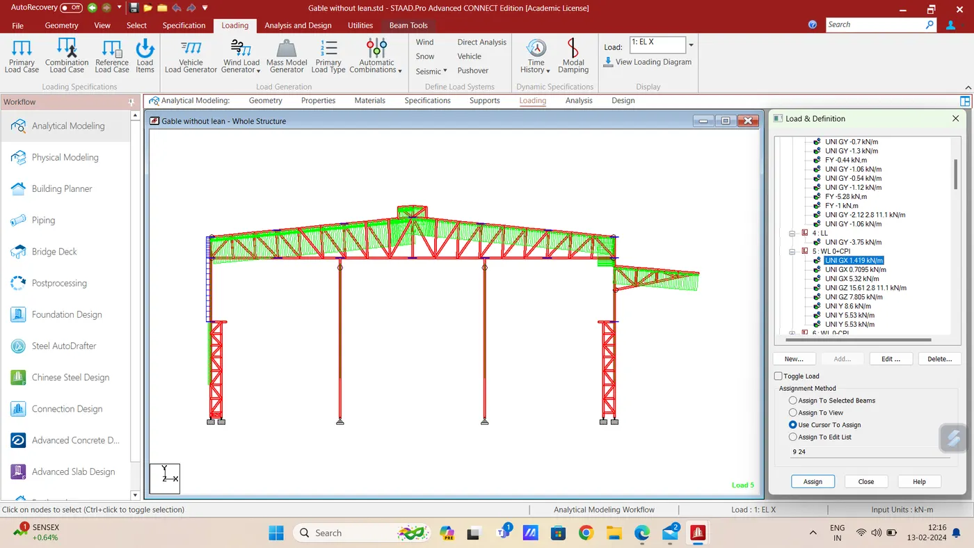
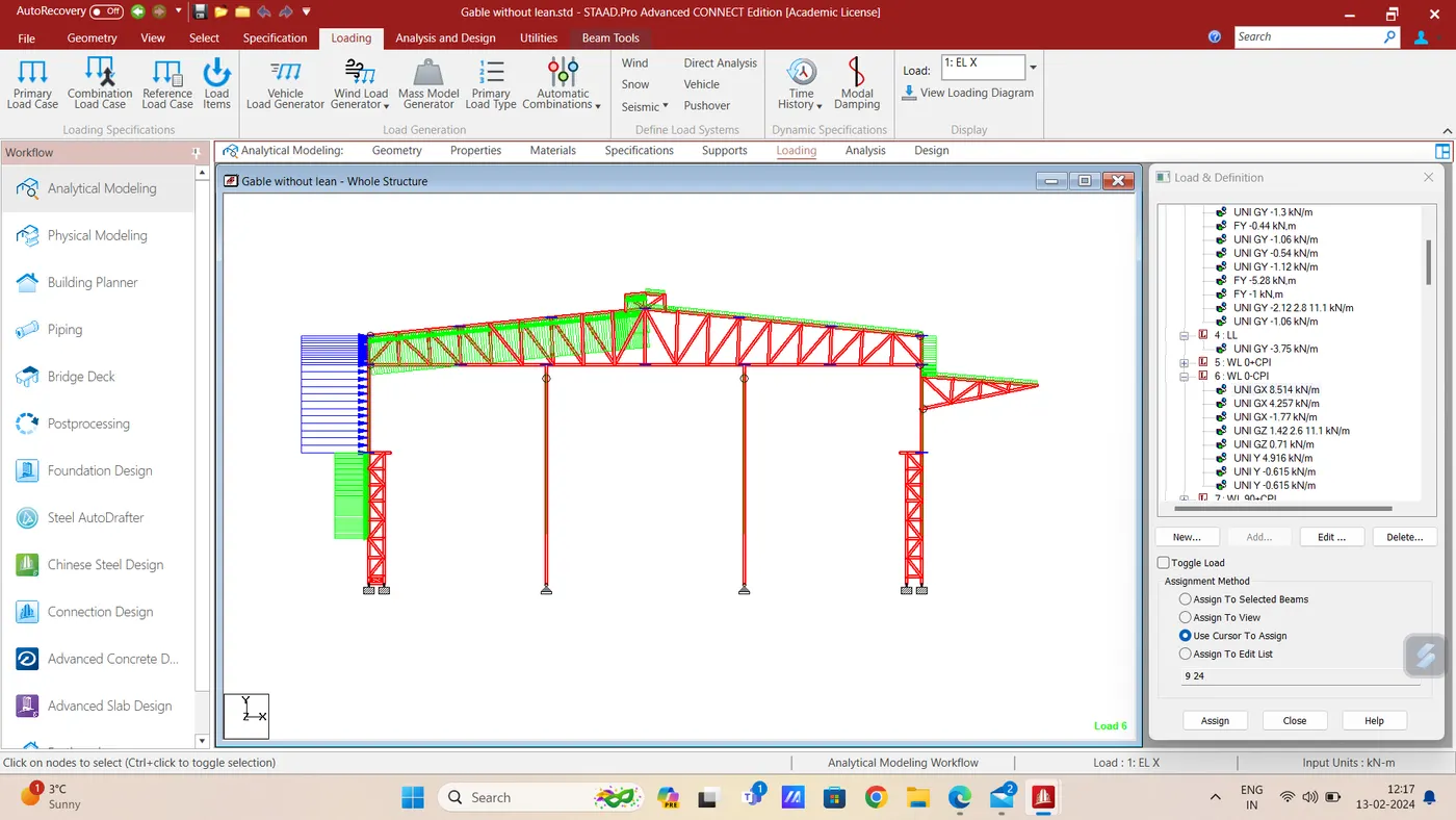
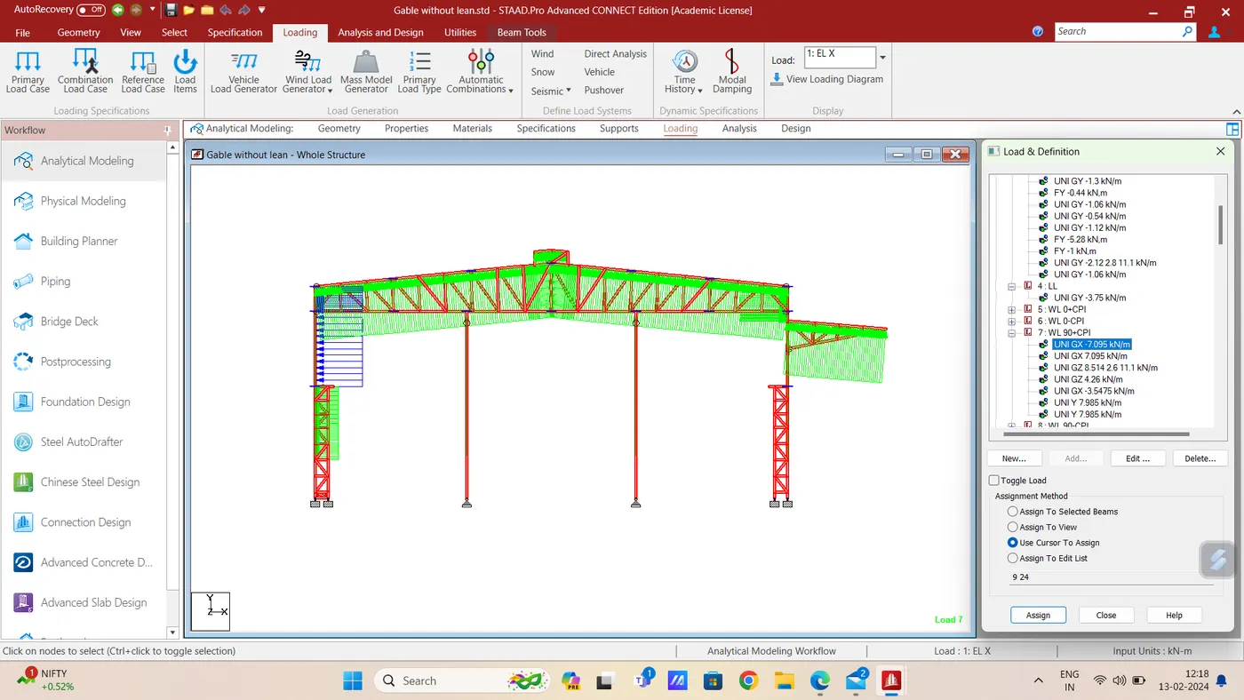
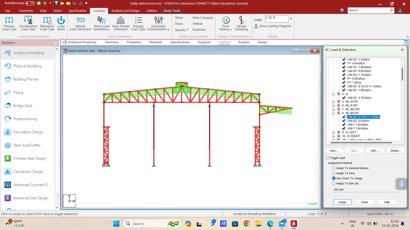
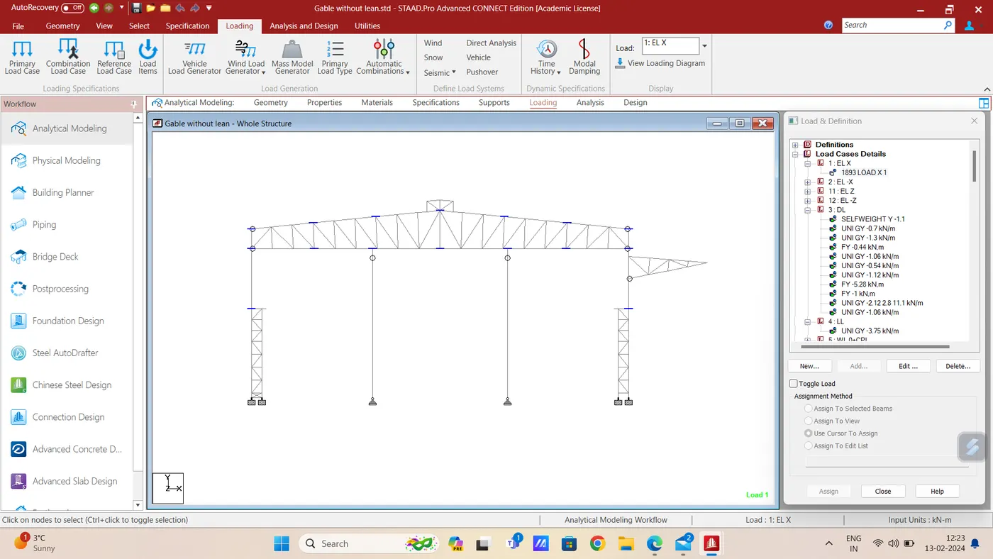
- Select Loading Tab, add Earthquake, Dead load, Live load, Wind load, Crane load and Load Combinations as shown below.
- Then Assign the above loads and load combinations to the members as shown below.
- Step 7:-
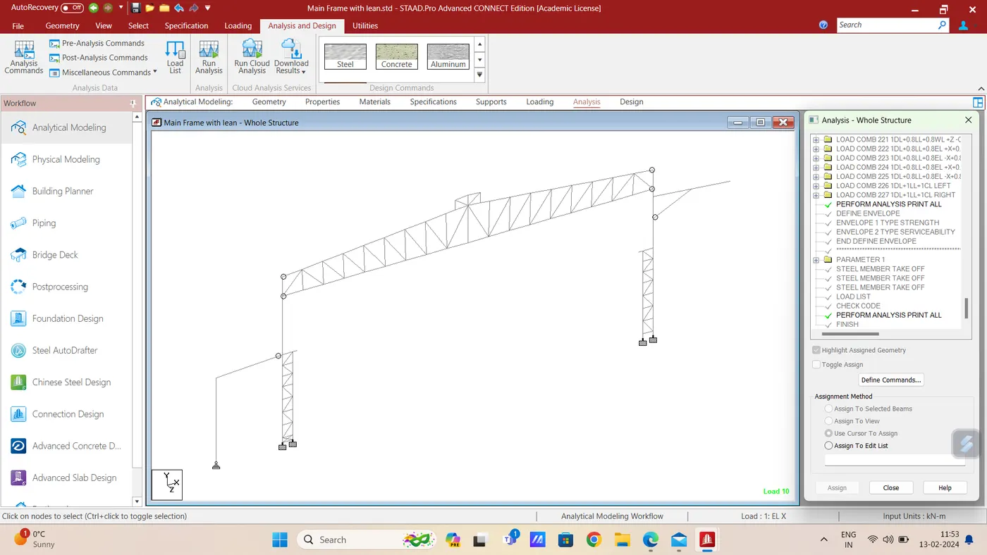
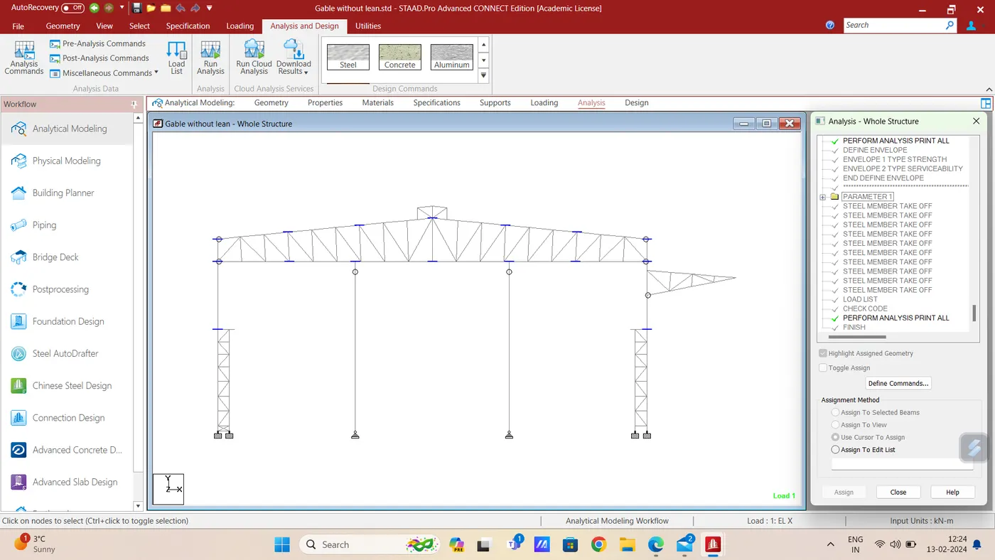
- Now go to Analysis Tab, and click Define Commands.
- Then create and assign Perform Analysis at each end of Earthquake load and Final of commands.
- Step 8:-
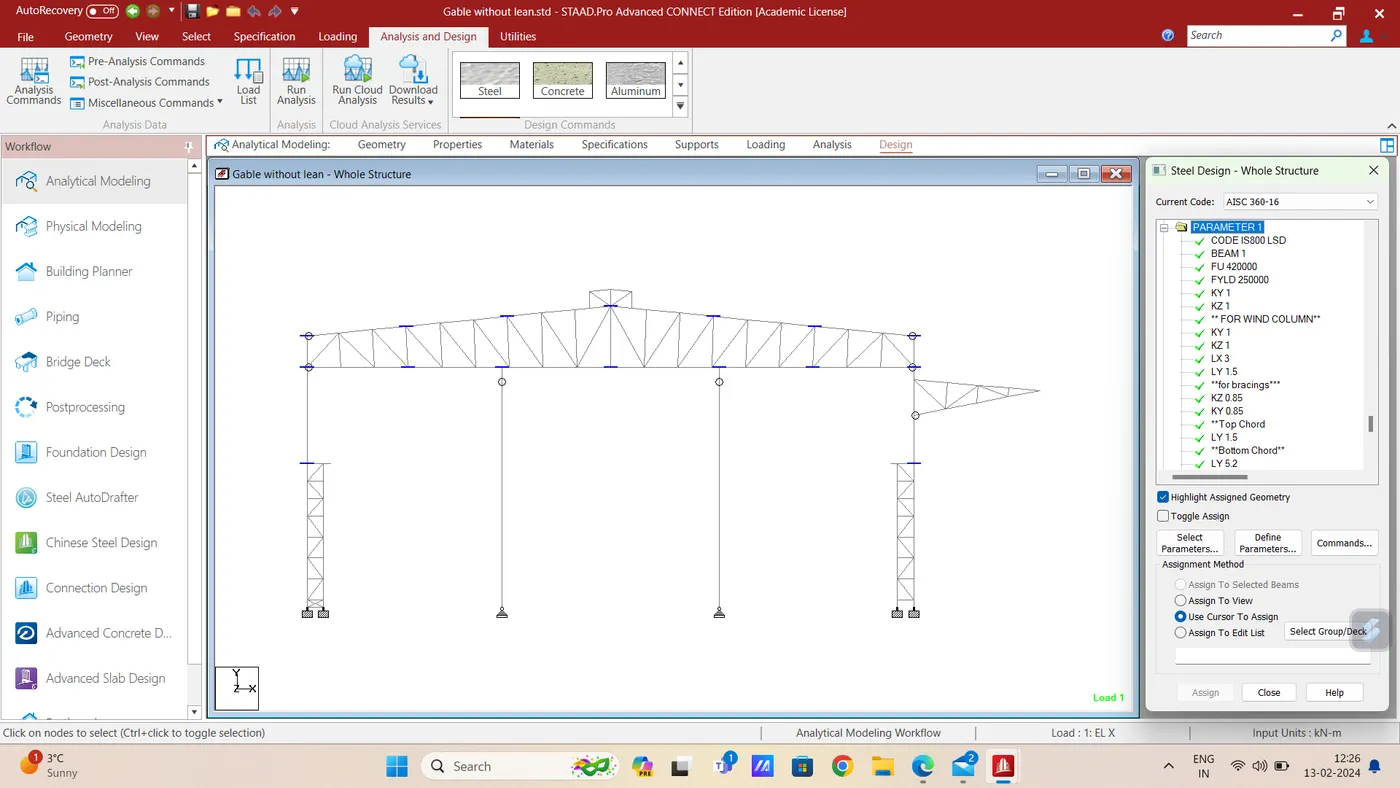
- Select Design Tab, Define Parameters such as Code, Beam, Kx, Ky, Ly, Lz, Ratio, etc.,
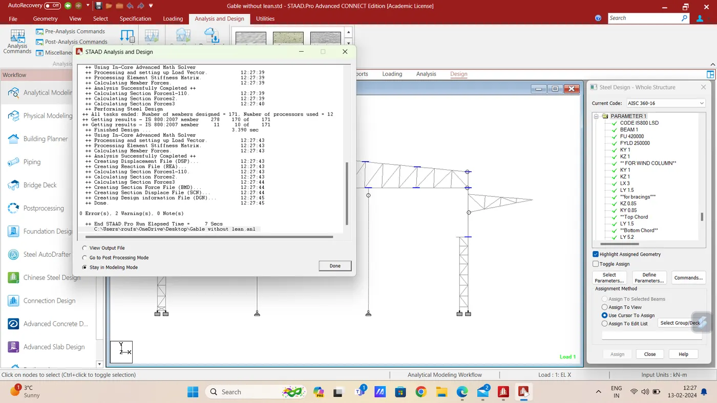
- Then click Run Analysis.
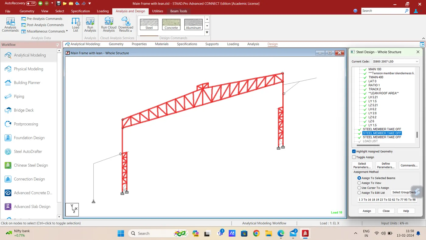
- Output shows 0 Errors.

- Step 9:-
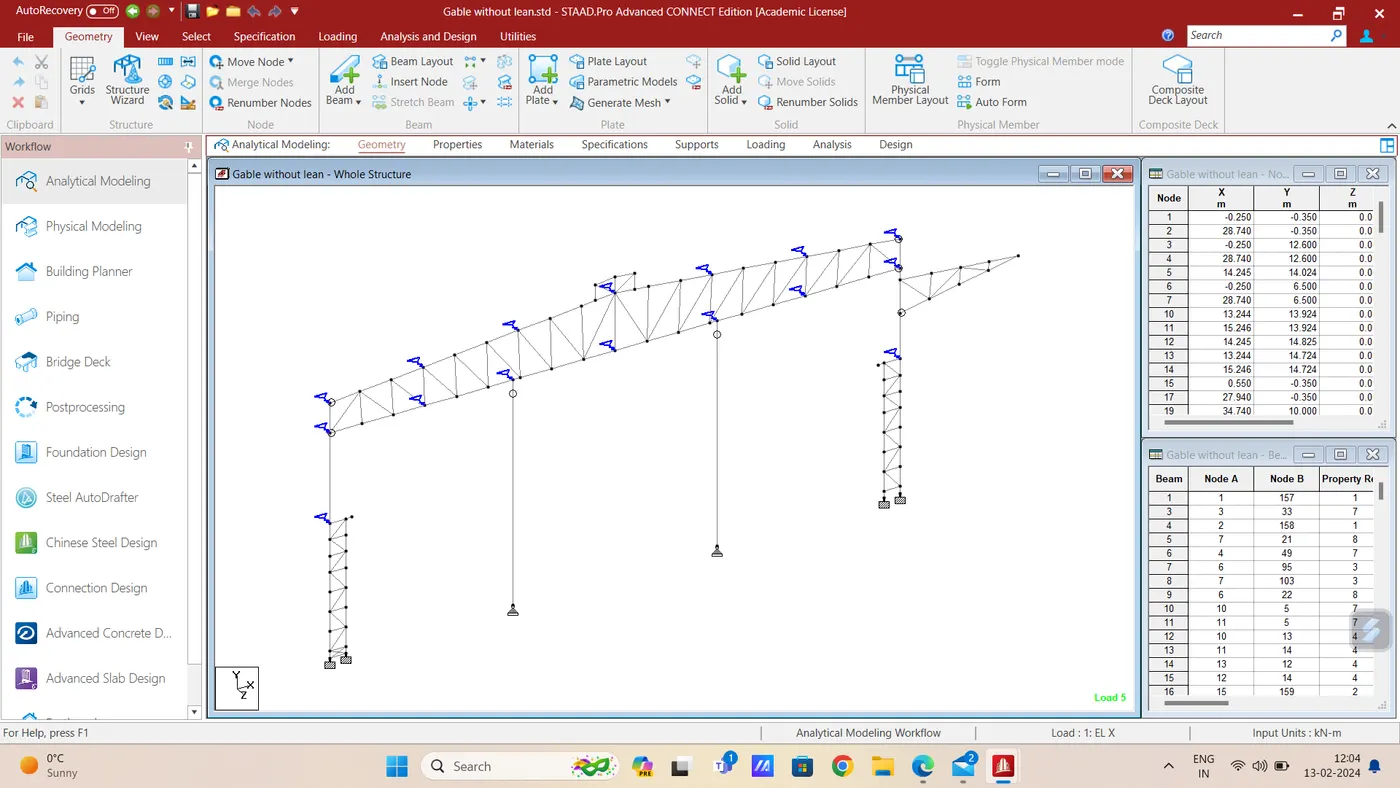
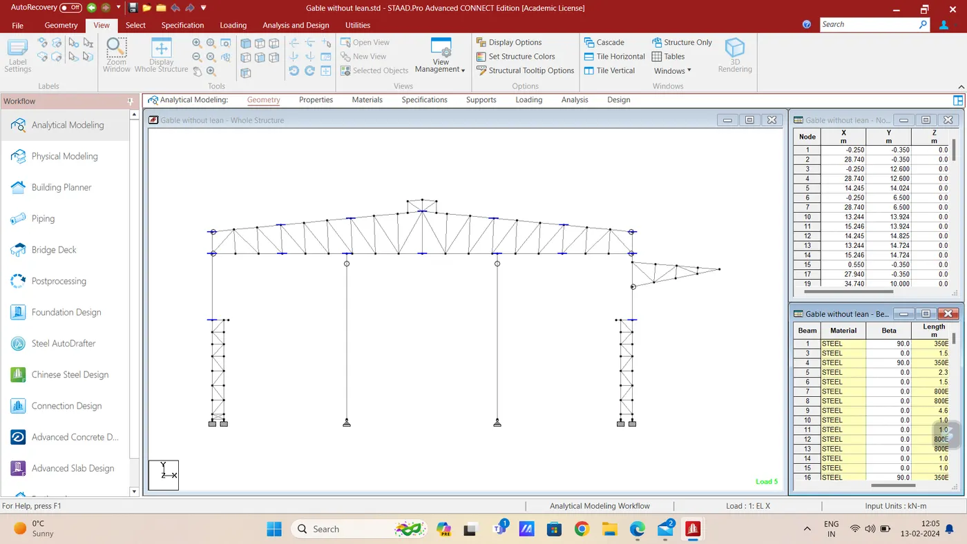
- Similarly model and design the Gable Frame as did in Main Frame.
- Only difference is Half of the loads only acts the Gable Frame.
- Result:-
- Model & Design a Proposed Coil Centre, Chennai using STAAD. Pro for following input from Client was done successfully.
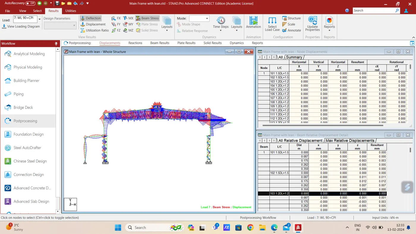
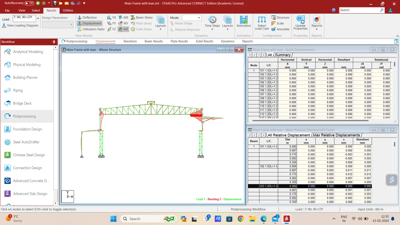
- Bending Moment diagram for Main Frame (Grid 2).
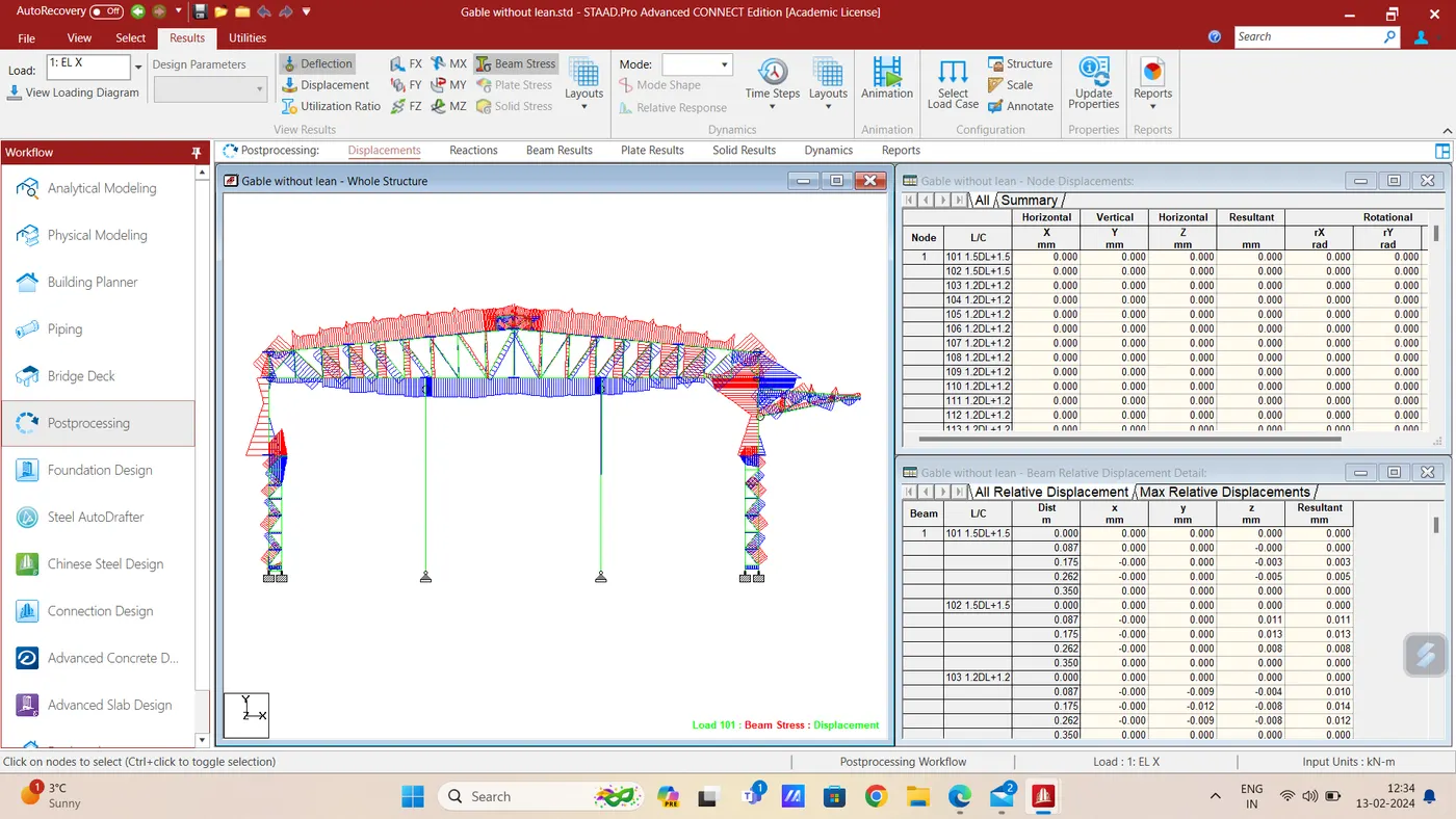
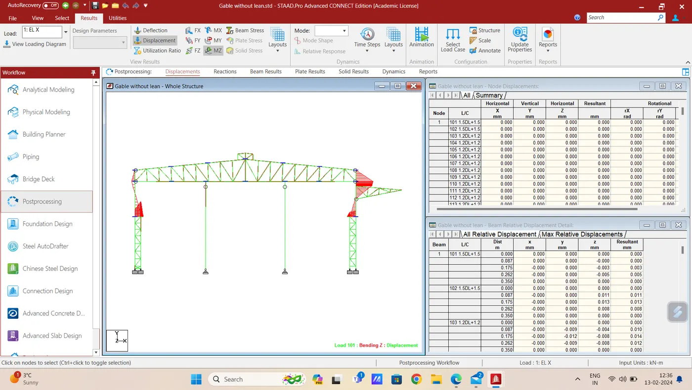
Bending Moment diagram for Gable Frame (Grid 15).