Project 1
PROJECT 1
WIRING HARNESS DESIGN
AIM
Design and develop the Wiring harness on Given V6 Engine and Prepare flatten view drawing in CATIA V5. Application of all Packaging rules, Industry best practices studied in this course shall be demonstrated in design.
INTRODUCTION
A wire harness, also commonly referred to as a wiring harness, is an exterior sheath used to cover some types of electronic wires. Generally, wiring harnesses are made of thermoplastic or thermoset materials that can help protect the cables from the environment.
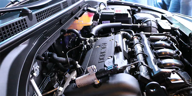
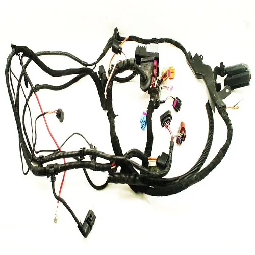
An Engine Wiring Harness is constricted Wires, Cables, terminals, and Connectors Controlling a vehicle's electrical system. It relays electrical Power and Control Information to Components Such as batteries, alternators, fuel injectors, fuses, audio systems, blower motors, fuel Injectors, and Computers. Wire harness companies customize it for every location, application, and design it interconnects. Also Known as Cable harness, it is more than just a collection of multiple of wires Put together.
It manages the key functions around the engine Including Engine controller, oil controller gate, transmission plug housing, air Pipe Sensors, Pressure Sensors, and Water Temperature Sensors.
How Does the Engine Wiring Harness Work?
There are many cables in the Engine Wiring Harness that work to Connect electricity to Your Vehicle Parts. This Vehicle Part has many Sensors, and they work to ensure that everything in your vehicle is in working order. Some of these major systems in your car are fuel and transmission. when you get a check Engine light, you have the Engine Wiring harness to thank.
It works by using these cables and a fuse box. They Wire the electricity produced by the engine to the various parts and sensors. It is created using High-temperature plastic or Rubber because the Engine heats up a lot. That Could Cause the Engine Wiring Harness to melt over time. And while this is a rarely Occurs, it does happen.
OBJECTIVES
· . Define all the Connectors Electrically.
· . Place all the connectors to the required positions on the given Engine 3D CAD model.
· . Place P-clamps and Fir Tree clips at the required position by following the packaging rules.
· . Create the Wiring Harness Routing with all the electrically defined connectors and Mounting Equipment.
· . Create Branching Point at required locations to create sub branches and connect to various connectors in the geometrical bundle.
· . Apply Protection Coverings as required.
· . Create Wiring Harness flattening for the final geometrical bundle.
· . Using the Drafting Workbench, create a Drawing Sheet with the flattened Wiring Harness.
DESIGN METHODOLOGY
Step 1- Download the Engine Cad Data and Required Connectors CAD data from the given Source.
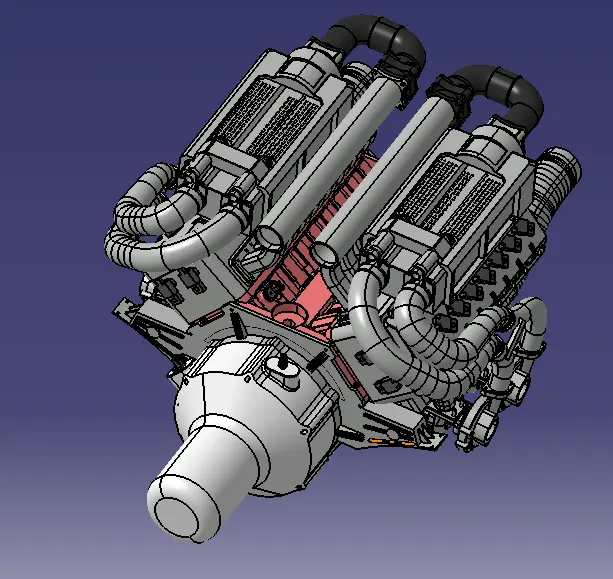
Step 2- Download the required Connectors from the Source and Convert the Mechanical Connectors electrically by using the electrical part design work bench by following below steps.
· First download the Connectors and mounting clip from the given link source.
· Get into Mechanical part workbench to create required geometrical parameters. Create Connector Connection point and bundle connection point on the required sides of the CAD part.
· Create axis system on the Connector Connection point Such a Way that the Y Coordinate facing normal to the connector face, X co-ordinate facing towards the locking mechanism and Z Co-ordinates facing to the top.
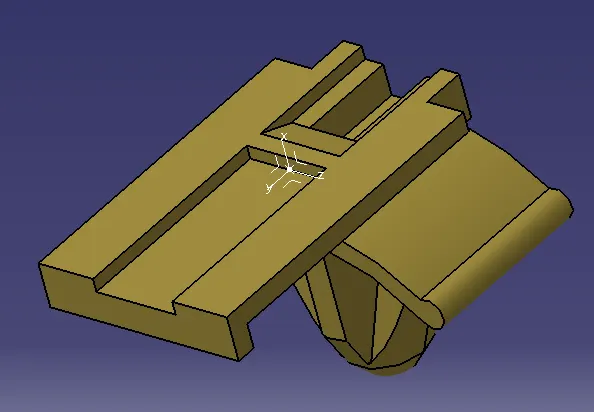
· Create Cavity Connection Point for Connectors having the cavity for mounting clips.
· Using the geometrical parameters Created.
· Define part as electrical connector.
· Define bundle connection point.
· Define connector connection point.
· Define Cavity Connection Point.
4 pole connector
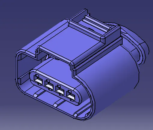
2 Pole Connector

2 Pole Connector
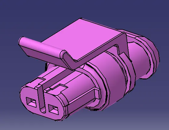
2 Pole Connector
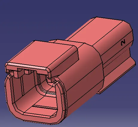
12 Pole Connector
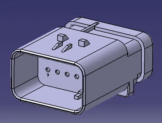
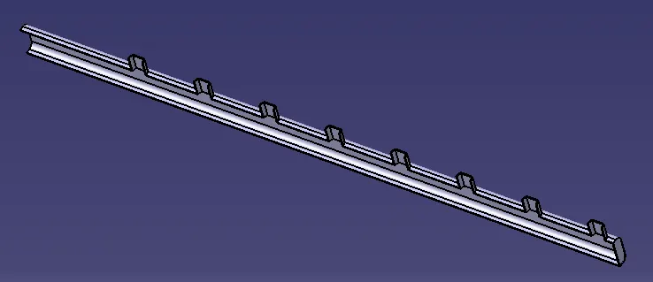
Step 3- Download and define the plastic channel electrically.
· Procedure for electrically defining the Channel.
· Create bundle entry point and exit point.
· Create a line Curve between the main entry and exit points for creating the multi-branchable using external curve inside the channel.
· Create 8 bundle entry points on the openings for connecting the injector connectors.
· Using the geometrical parameters define the channel electrical using the define mounting equipment option.
· Create define bundle entry points using the " define bundle connection point option.
· Create Channel symmetrical and define all the required geometrical parameters and Electrical Properties.
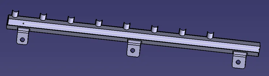
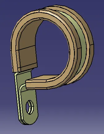
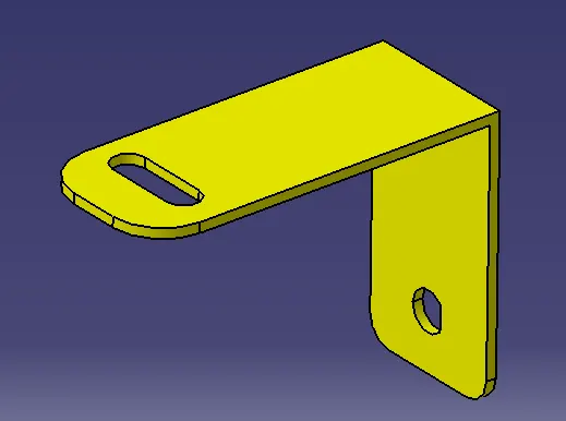
Step 4 - Download and define P-clamp, L-clamp and cavity clip.
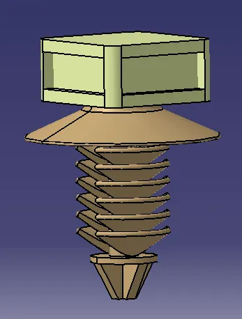
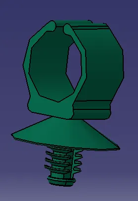
Step 5:- Create new Product file for inter Connection Connector and Cavity Assembly.
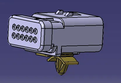
Step 6- Creating the Context assembly:-
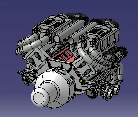
Context assembly is nothing but the product file which contains the engine 3D-CAD data and the engine harness geometrical bundle. Here the geometrical bundle product contains all the connectors and other mounting equipment, clips and clamps which are electrically defined for the assembly. Sheet metal L-clamp are added in the main context assembly. Then we need to switch into the Electrical Harness Assembly workbench and Geometrical Bundle Product file should be electrically defined using the Define Geometrical Bundle Option before adding any parts into it.
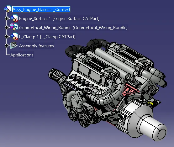
Step 7- Adding 4 pole connectors to all fuel injector sensors as well as for the camshaft sensors.
4 pole connectors should be added in the geometrical bundle using copy and paste connector. Connectors can be added again by copy pasting the 1st imported connector.
Place the Connectors on all the fuel injector sensors and cam-shaft sensors using the manipulation tools like move, smart move, snap tool and also using the compass.
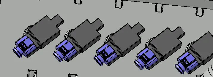
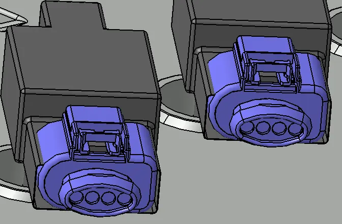
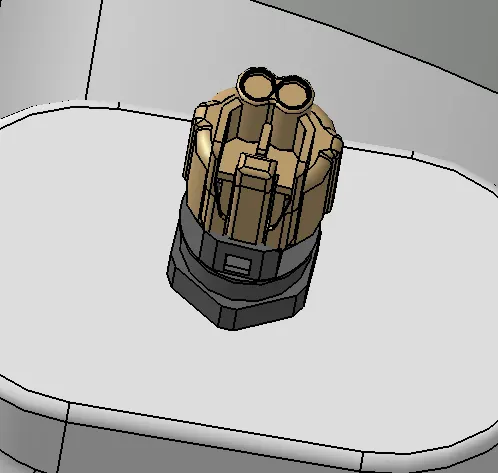
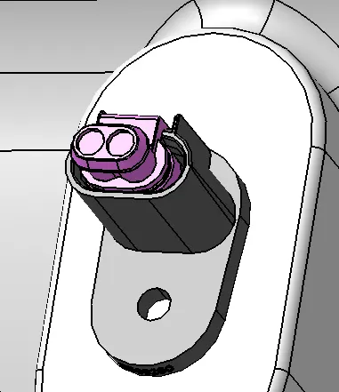
Step 8:- Adding all the other Connectors for Sensors like Coolant heat Sensor, neutral position sensor, Speed Sensors.
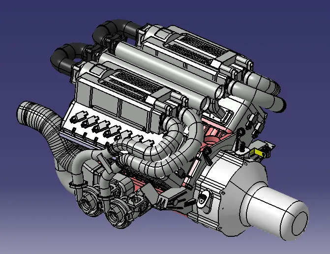
Step 9 :- Placing the Interconnection connector and L-clamp Support
However, Situation of interconnection connectors are not similar to device connectors. Interconnection connectors are not parked with any device but should be parked with the Help of clips/clamps/ Sheet metal Bracket etc. Possible to the Packaging conditions.
Un parked Connectors Can Create Following Issues :-
o Rattling Noise.
o Physical damage to Connectors.
o Uncontrolled Harness Routing.
o Manual errors during assembly because of undefined parking.
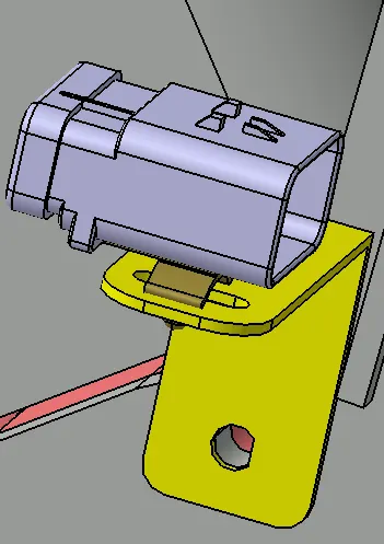
Step10-: Add P-clamps for proper Routing of the harness Bundle.
Adding supporting components like p-clamps and firtree clip Can help the harness bundle provide proper routing and also help to prevent the Harness bundles fouling from unwanted mechanical components.
· P- clamp and the Fir Tree can be placed at required locations to ensure best possible routing for the Harness Bundles.
· The p-clamp can be mounted to the holes provided on the Engine Block in which the Screws to tighten the Engine Block.
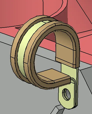
Step 11 :- Placement of Channels at the required locations. Use of plastic guiding channels are recommended to meet the clearance in critical areas if it is difficult to achieve by use of clamps.
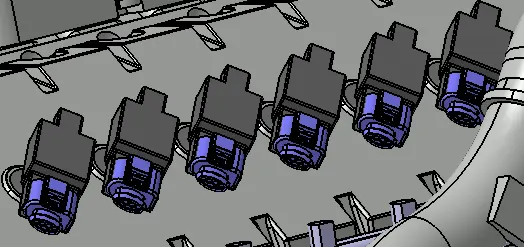
Step 12 :- Harness Routing Procedure for the channel :-
· First, we need to create multi branch-able bundle using the External curve option and select the line which we created earlier.
· After Creating Bundle Segment Create 8 Branch points inside the Channel for Creating Sub-Branches for the injector sensor connectors.
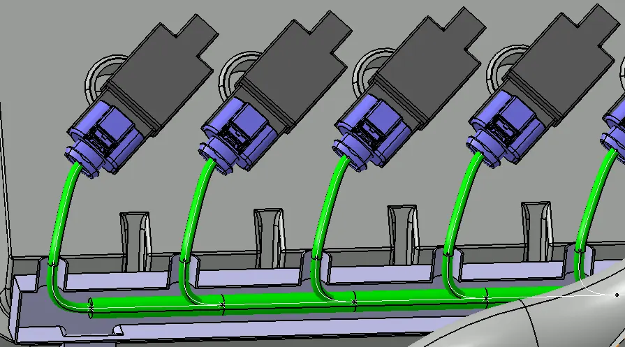
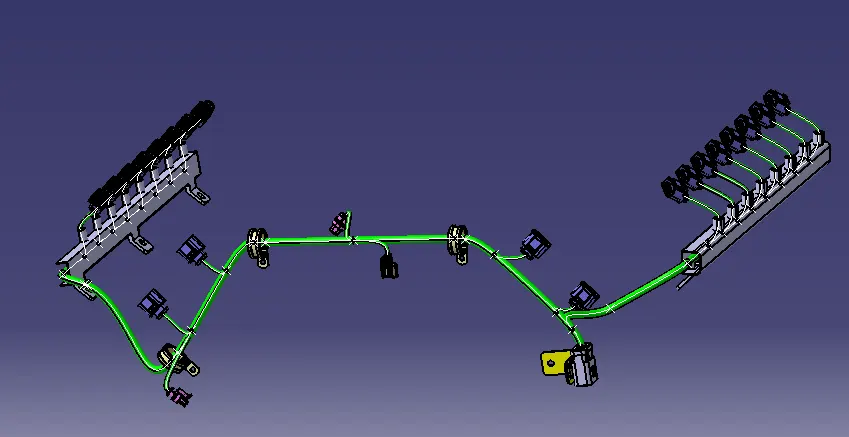
Final Harness Assembly for the Engine :-
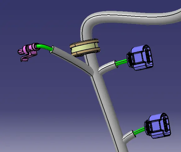
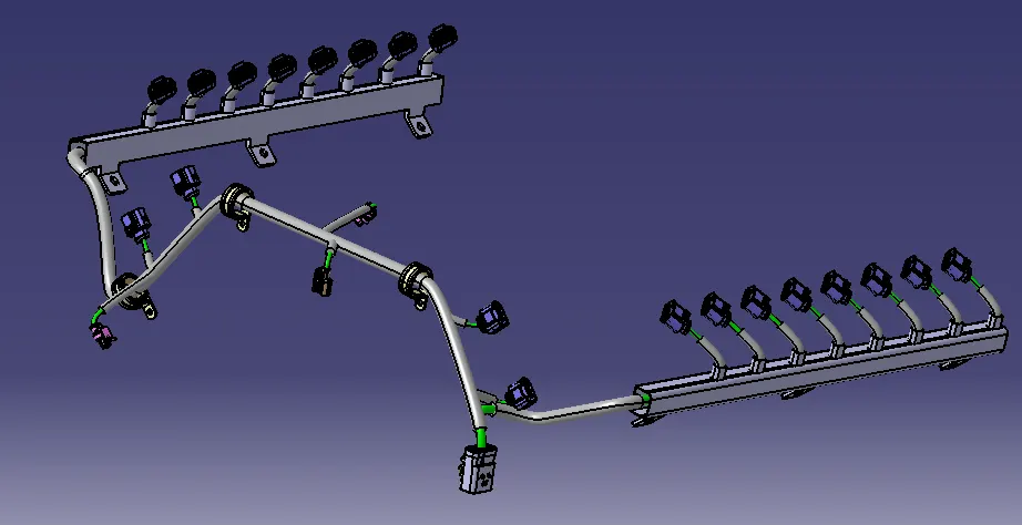
Step13: After finally Completing the wire Harness Routing by following the Packaging Rules we need to Provide Protection Parts Wherever necessary. Slit-COT tubes, cotton tapes are added on the wiring Harness Bundle as Shown below. The top part of the Plastic guiding channel will also be added at this stage.
Step 13 Electrical Continuity check
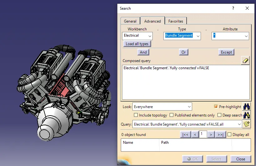
· We need to ensure that Entire Bundle is Fully Connected.
· Go to edit and then click on Search command. Go to advanced. select workbench as Electrical, type as Bundle Segment and attribute as fully Connected.
· Then select result should be as True or False and then click Search to see the connectivity analysis result.
Conclusion:
In this way, we have routed wiring harness for the Bugatti V16 Engine in CATIA V5
Project-1 Files: https://drive.google.com/file/d/1O3kooYI_uqXzQtHAYjg9BQi4XHyTrmnC/view?usp=drive_link
The file was not getting upload. So, I attached the Drive link.
I Can't flatten my model,even after attend some Sessions and so many methods.So I upload it with Wiring Harness only.