Project 1
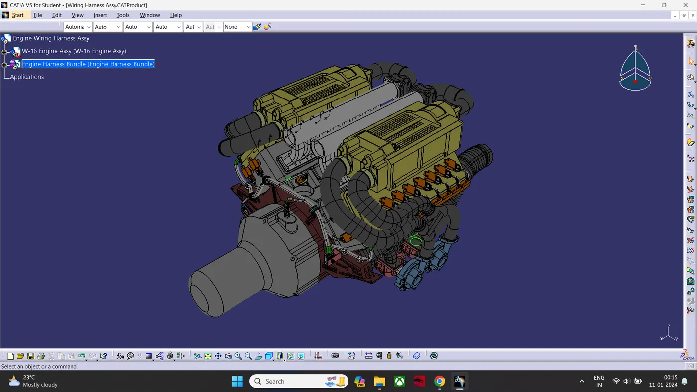
Engine Wiring Harness Using- CATIA-V5:
Aim:
- To Route the wiring harness on given Engine.
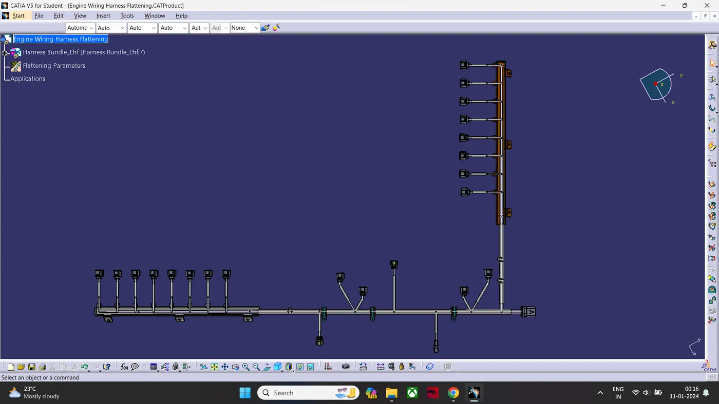
- To Prepare the Flattened View of wiring harness.
- To prepare the Drawing sheet.
Wiring Harness Routing Methodology:
- Downloading the given CAD data.
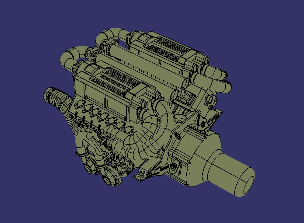
- Define The geometrical parameters to the connector. Create connector connection point. create bundle connection point. Create Axis system in Connector Connection Point. Then Define It as Connector In Electrical part workbench. Then Define Connector Connection point & Bundle Connection point.
- Create a Main Product Named= Engine Wiring Harness Assembly
- Then Create a Product Under the Engine harness assembly Named= Engine Wiring Harness Assembly.
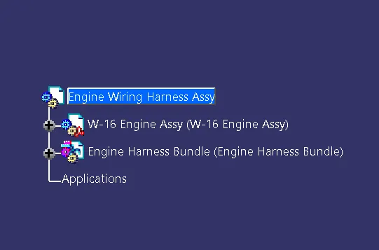
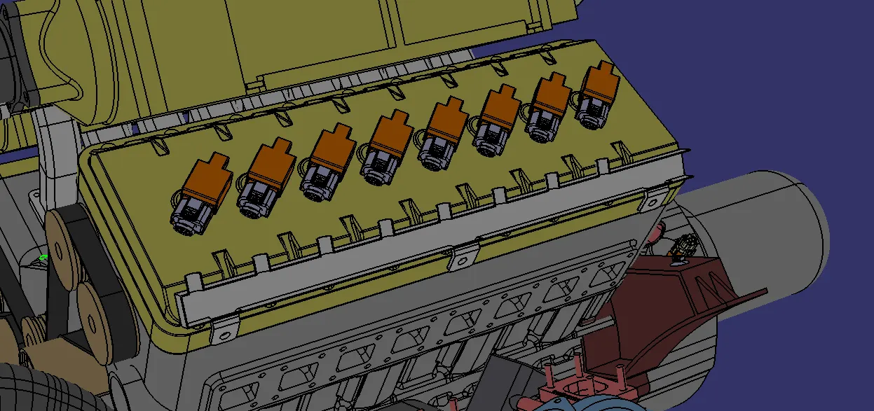
- Then insert all Connectors Into Engine wiring harness assembly Product.
- Then convert Engine wiring harness assembly Product into Geometrical Bundle.
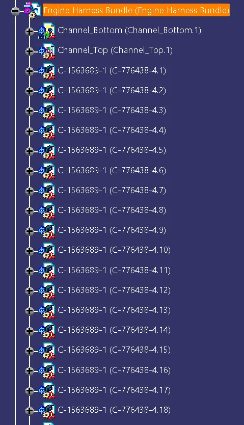
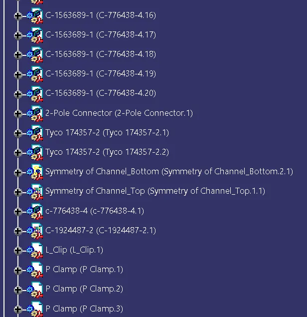
- Placing the required connectors to the Engine assembly.
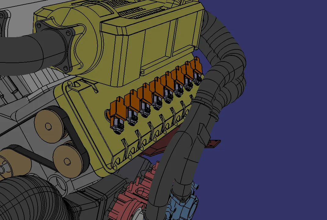
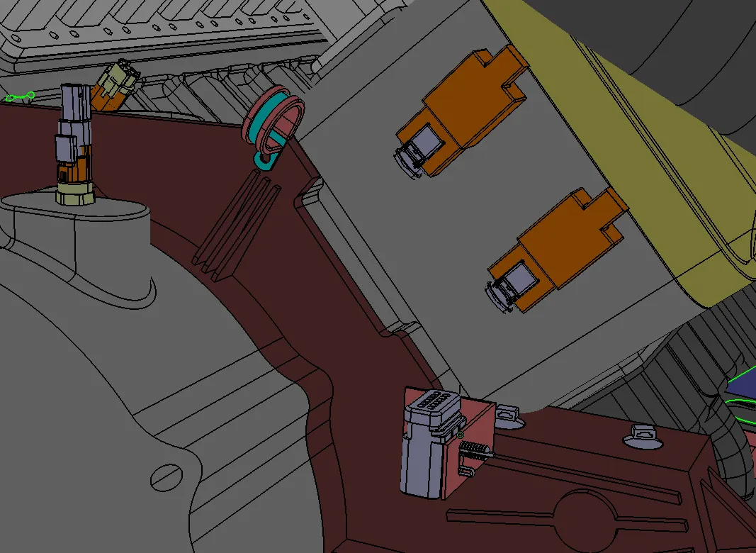
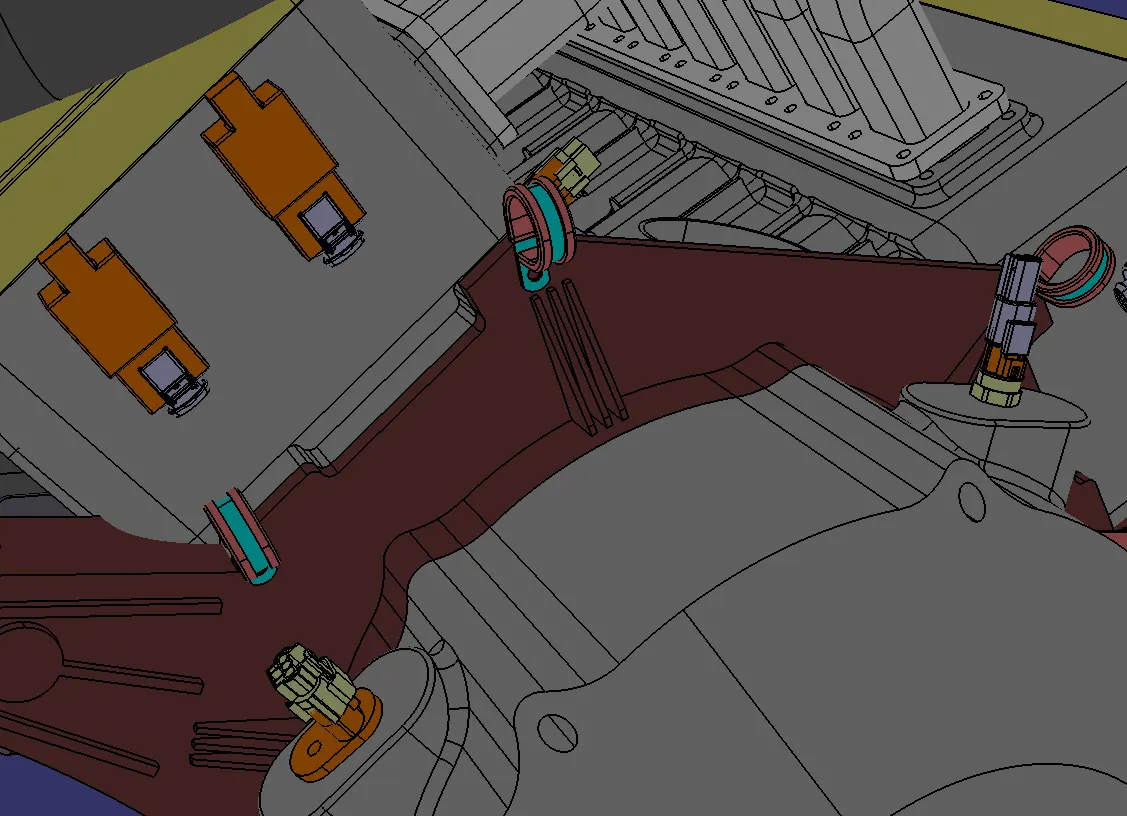
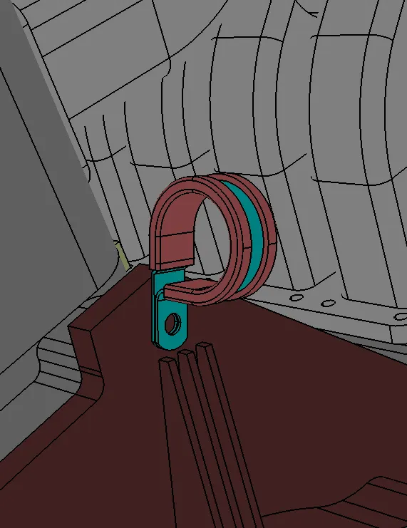
- Placing the required clamps & Clips to the Engine Assembly.
(L-Clip & Cable Tie Clamp)
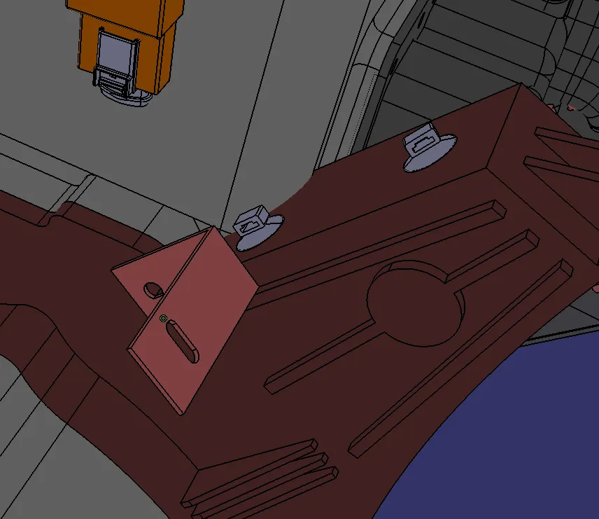
(P-Clamp)
- Creating a Mounting housing To Route The Bundle to Spark plug Coils.
- Creating A Multi-Branchable.
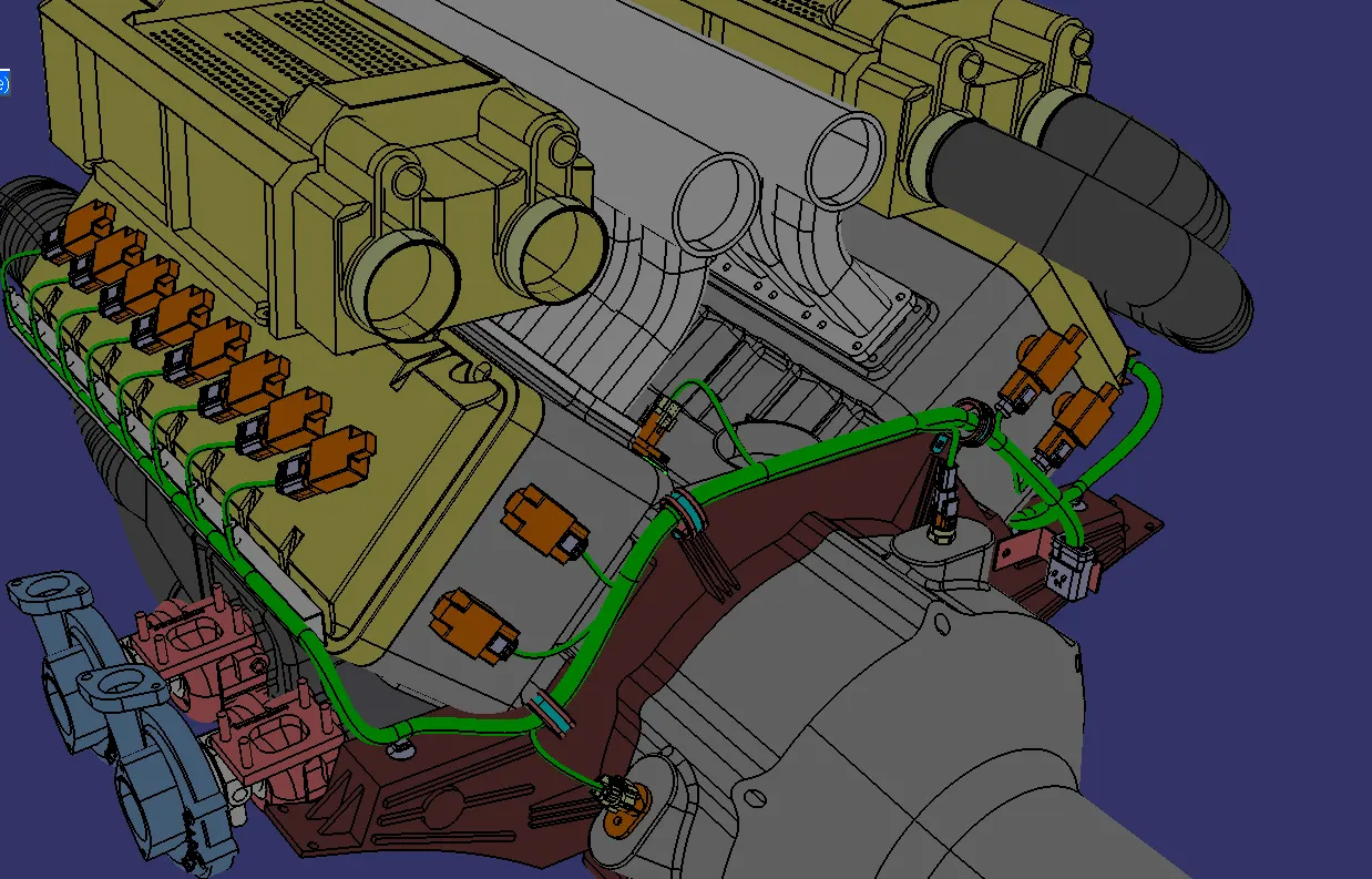
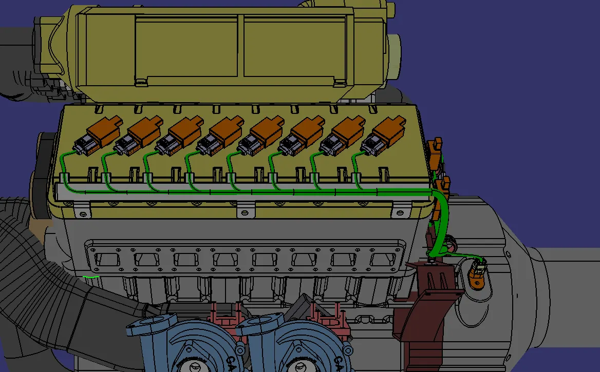
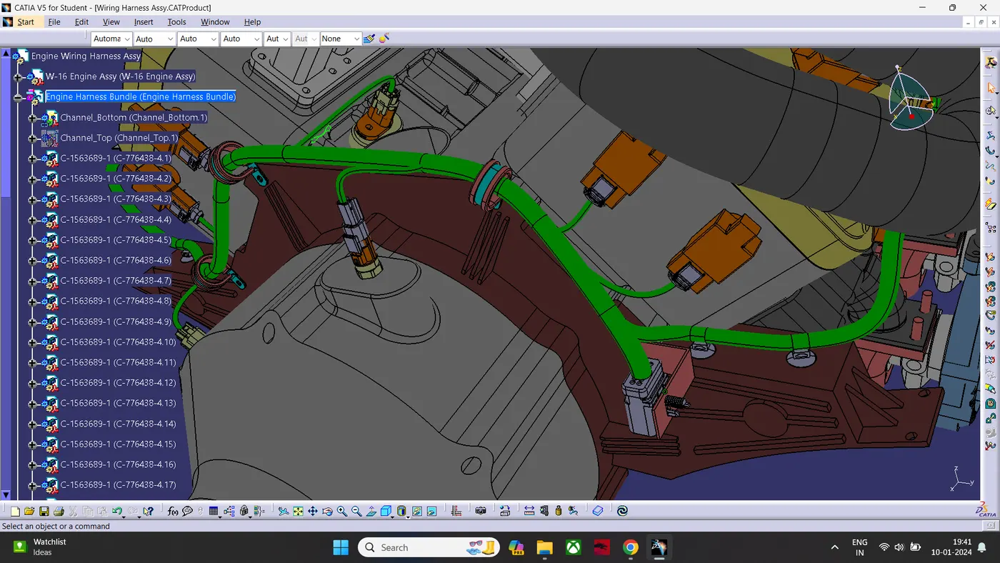
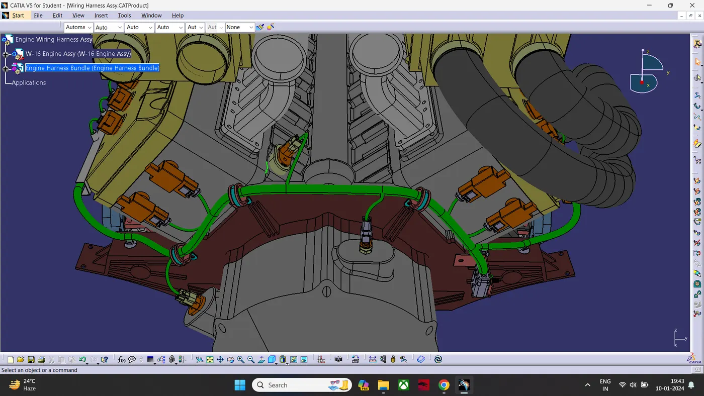
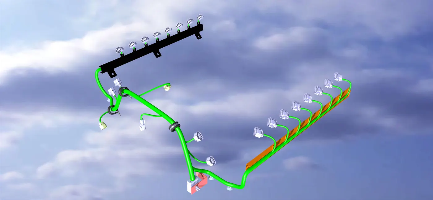
- Then Creating COT Tubes.
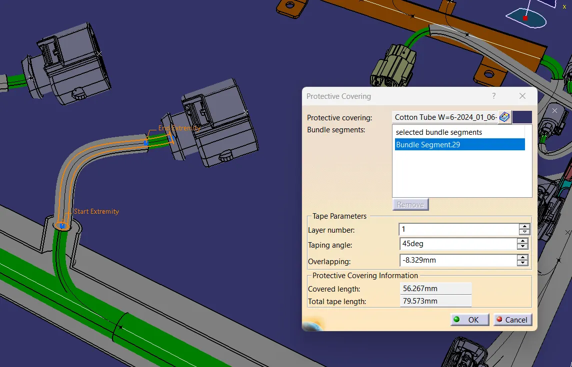
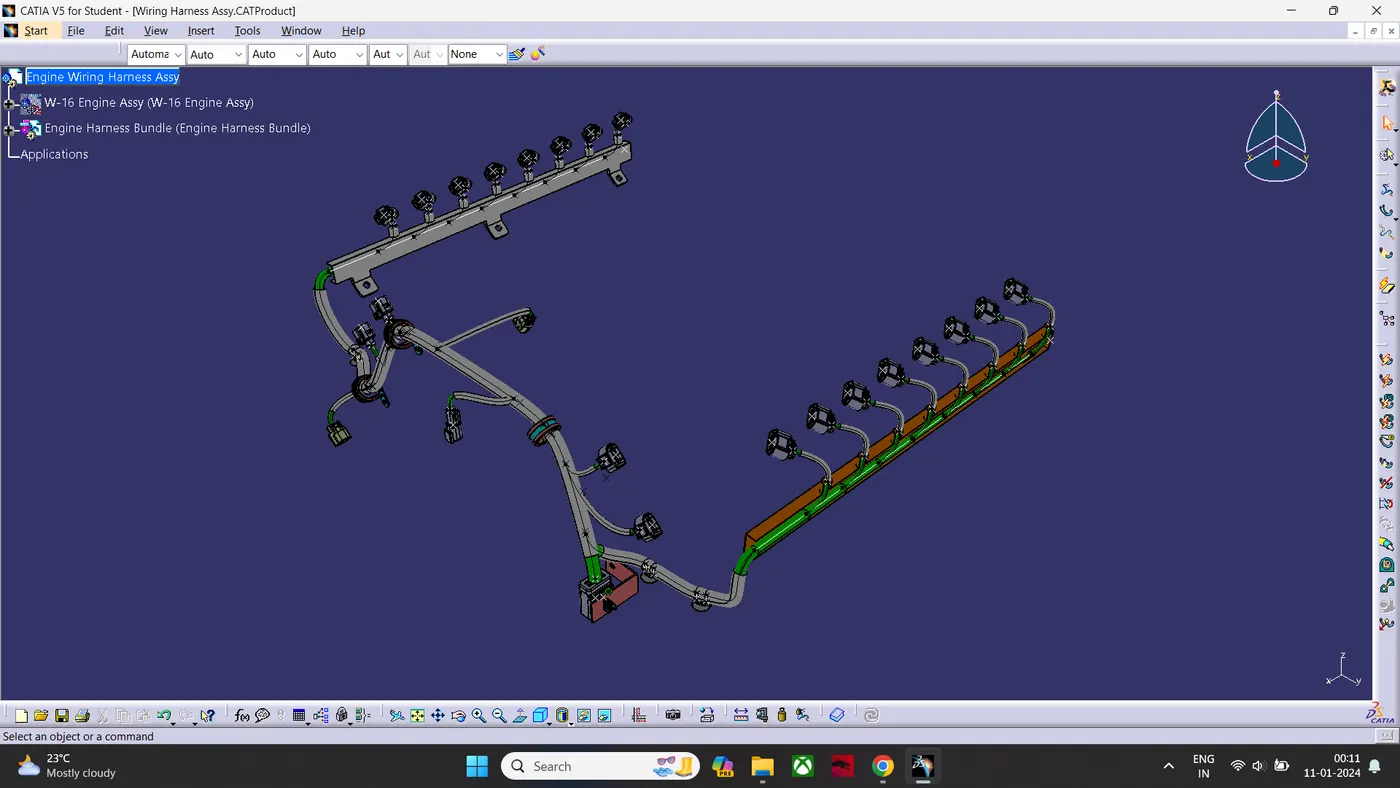
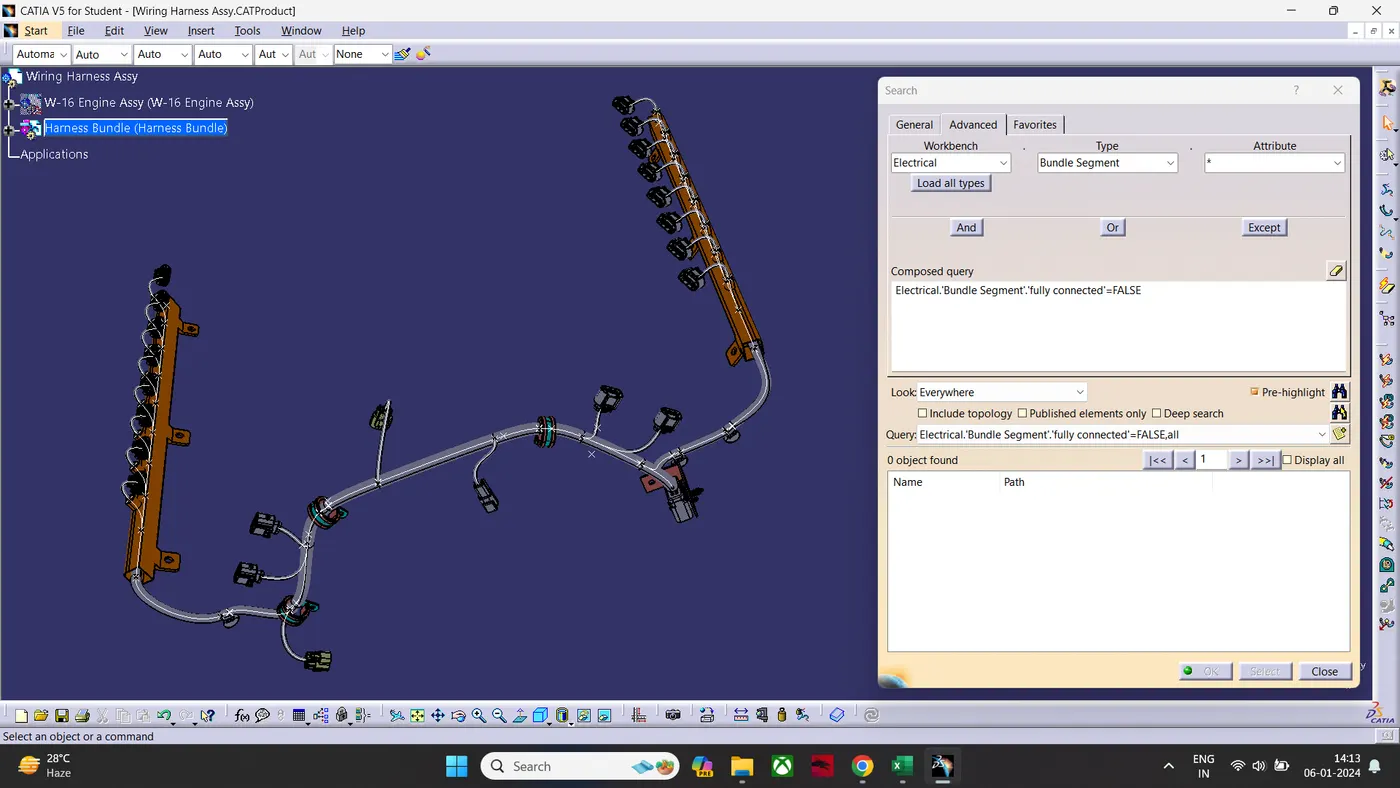
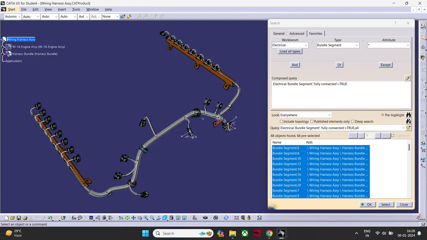
- Checking the Bundle if it is Fully Connected.
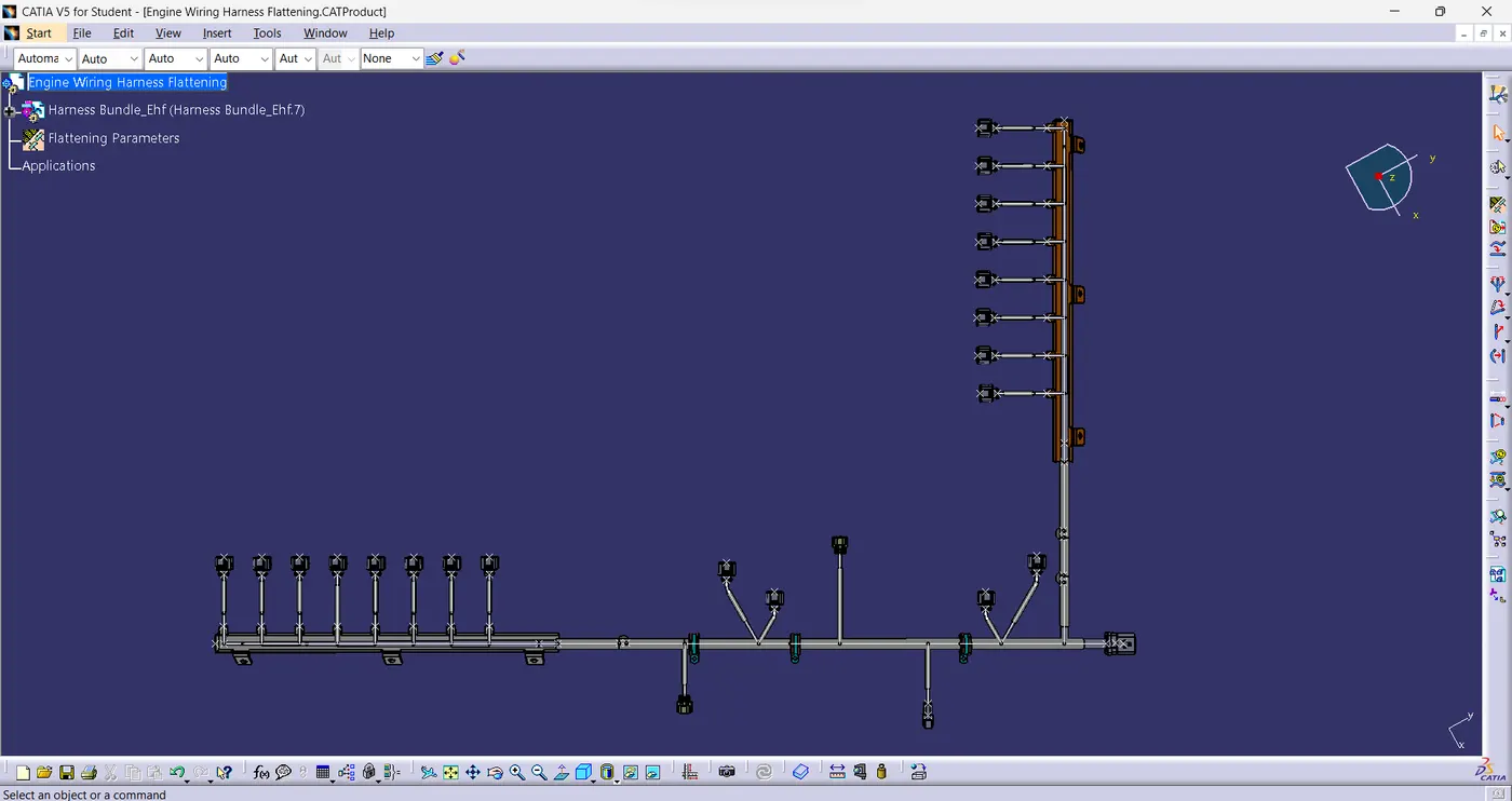
FLATTENING METHODOLOGY:
- Create a New Product Named Engine Wiring harness flattening.
- Switch the workbench to flattening Workbench
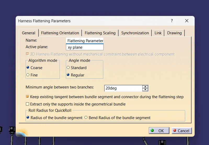
- then defining the parameters
- Then sideloading the week-4 Harness Assembly.
- In Electrical Harness Assembly- Inserting the wiring harness assembly by Extract Command And Required Face.
- Then Flatten The Assembly By Flatten Command and Selecting the Required Face & Required Branches.
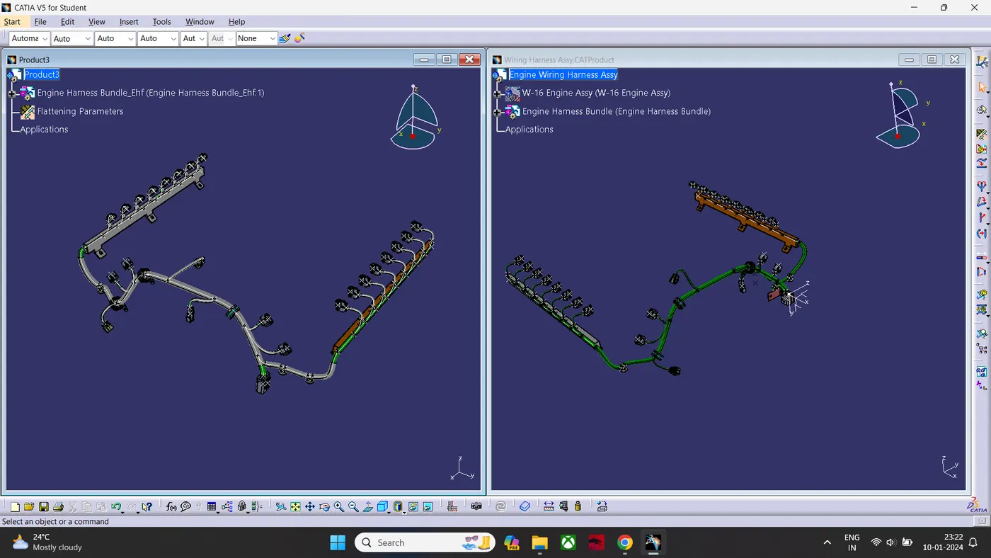
- Then Flatten the Bundle By using the Flatten command.
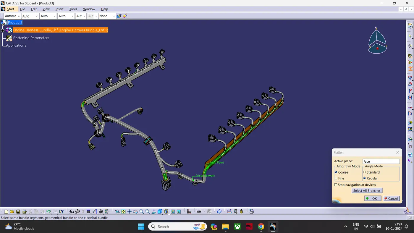
- Then Bend the Harness By Roll Command.
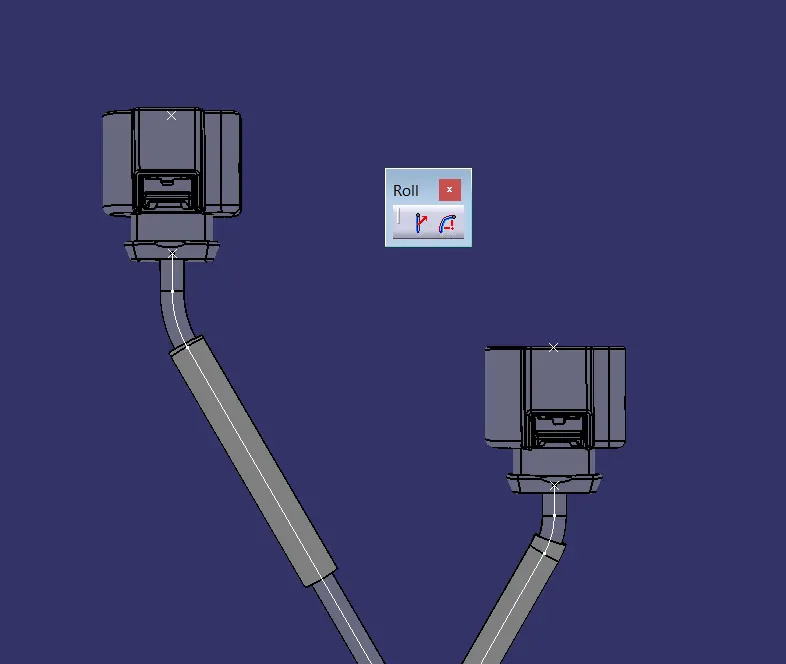
- Rotate The Branch By Using Rotate Command.

- Then if a branch needs to Increase in length for Appearance It Can be fake scaled by using the Scale Command.
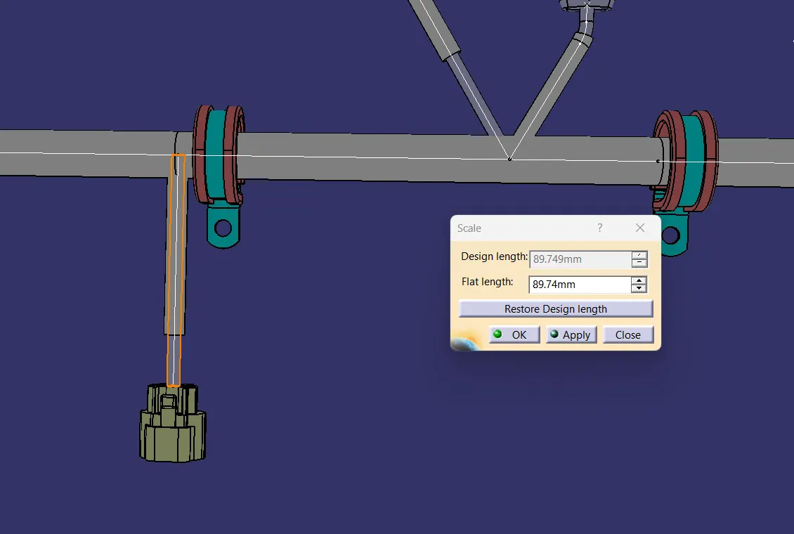
- Using the Compass to Manipulate the Connectors, Mounting Equipment & Clamps To Position it.
- By using synchronize Command Can be link and unlink with main assembly.
DRAFTING METHODOLOGY:
- Creating An New Drawing file.
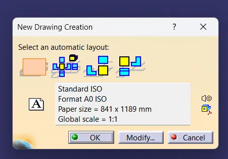
- Importing the front view of Flattening Assembly.
- Changing the properties of the view.
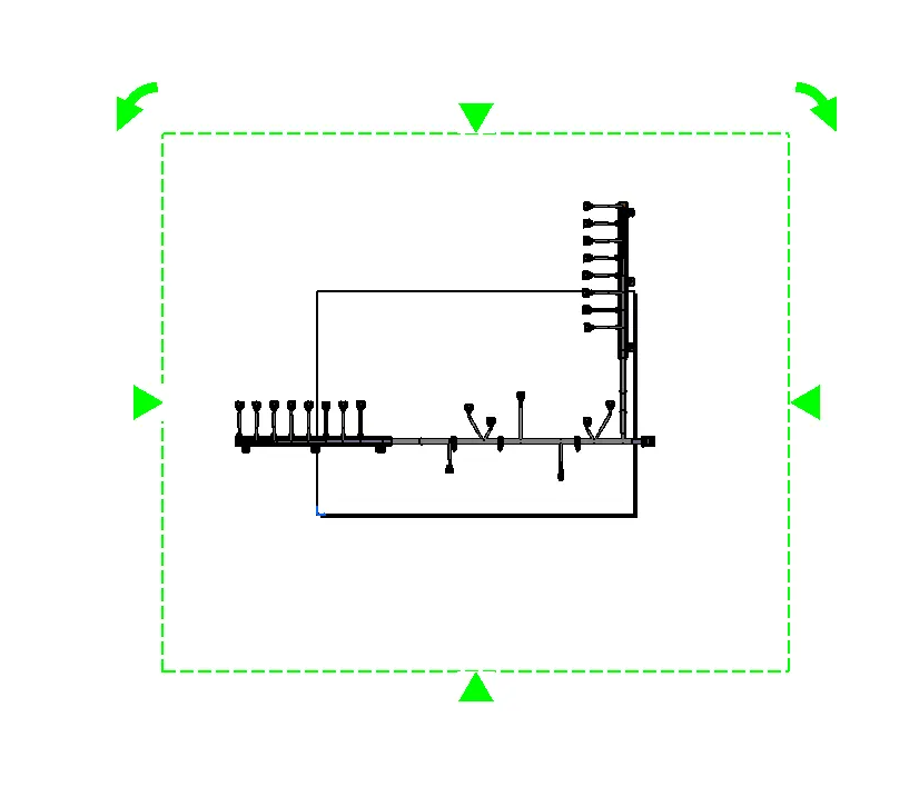
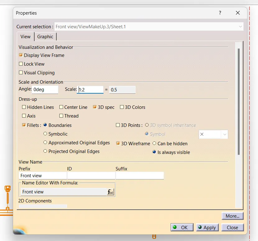
- To fit the Assembly in Drawing sheet I have scaled it to 1:2 Ratio
- To differentiate the Cot Tubes and Bundle I have shown the 3D Wireframe is always visible.
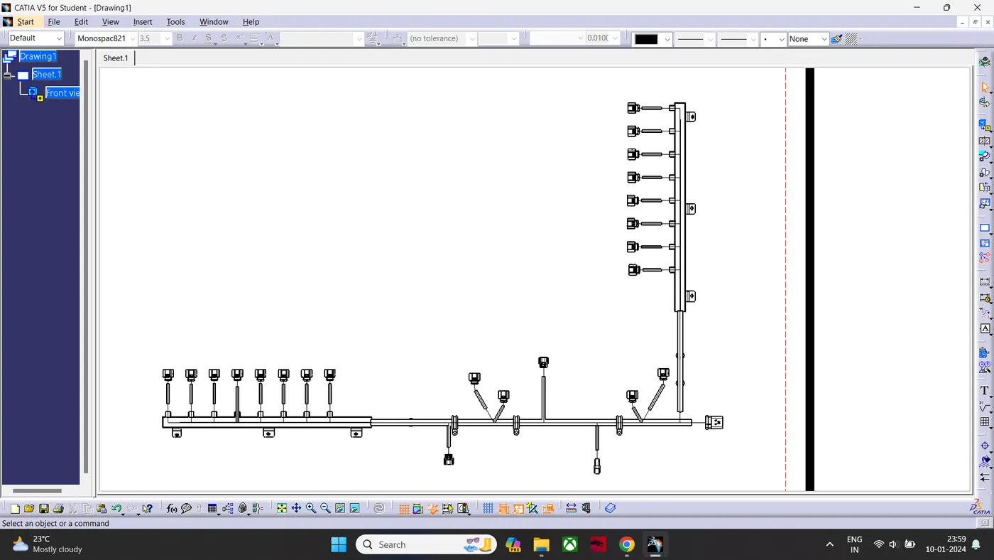
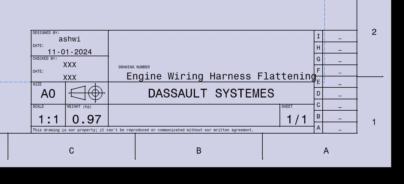
- Then Switching to sheet backround to create a Frame & title block.
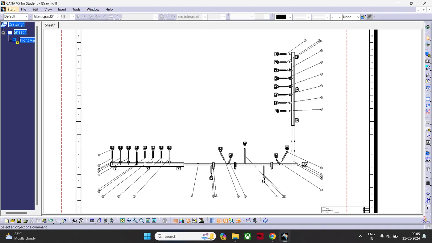
- Switching Back to working view to generate Balloons.
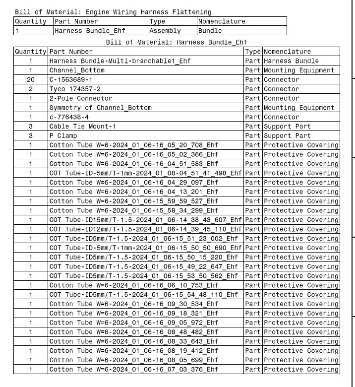
- Then Generating Bill Of Material.
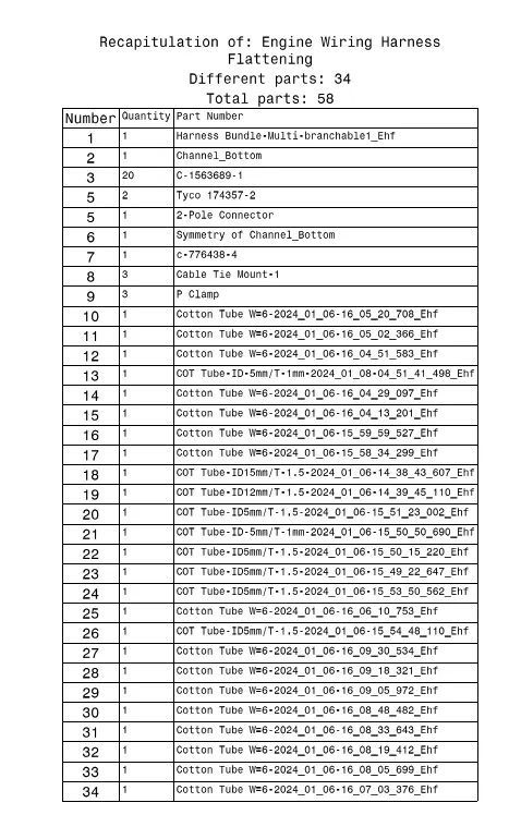
Finished Drawing Sheet:
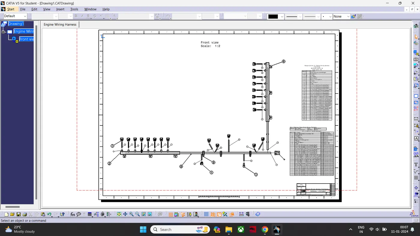
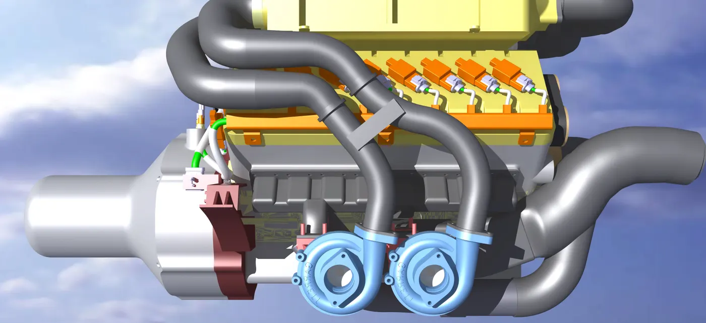
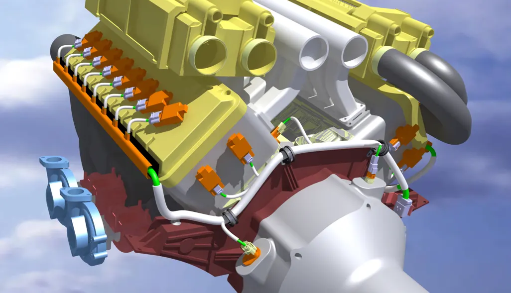
Different Views:
Engine With Wiring Harness: