Project 1
WIRING HARNESS FOR ENGINE
PROJECT-1:
Aim-
To route the wiring harness of Engine model, protection covering and prepare flatten view drawing in CATIA V5.
Objective-
Objective of this project is to route the wiring, protection covering and prepare flatten-view drawing for the given V16 engine model and considering all types of packaging rules constraints while routing the wiring harness .All necessary detsils like clearance/clamping selection,harness fixing requirements,harness continuity should be provided in order to design the wiring harness.
GIVEN DATA:
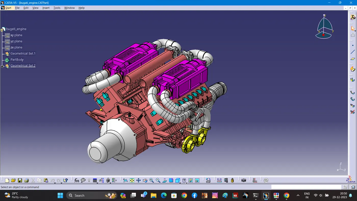
- The above figure shows the 16 valve Bugatti Engine where 8 cylinders are placed on the right side and 8 cylinders are placed on the left side.
- There are total 16 injectors where 8 injectors are used for 8 cylinders on right side and 8 injectors are used for another 8 cylinders on left side.
- Also there are 4 cam-shaft sensors, so there are total 20 sensors that we have to connected electrically.
- Generally, 4-pole connectors are used for fuel injectors of the engine.
- The engine will also have an interconnection connector which will connect the engine to other parts of the vehicle. We will be using a 12-pole electrical connector with a mounting clip feature as an interconnection connector.
- The plastic guiding channel used in this harness should bemade of a material that can withstand at least 150 degree Celcius.
- The bend ratio for the all bundle segmets should be 1.4
Step1-Creating Context Assembly:-
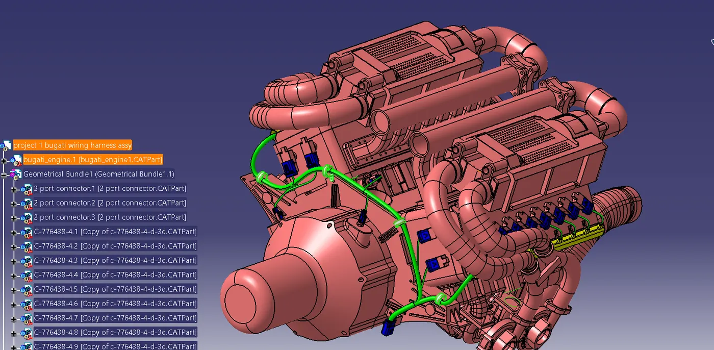
A context assembly has to be created which will serve as the main assembly for engine harness. The context assembly will contain the 3D-CAD data for the V16 engine and the engine harness geometrical bundle. If any sheet metal brackets are required then they are added in this "ASSY ENGINE HARNESS CONTEXT".
Routing to the guiding channel:
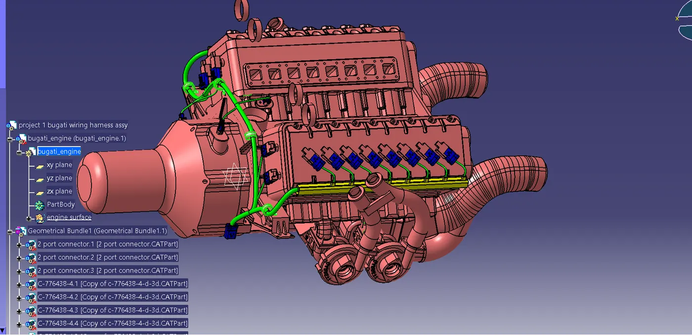
Another branch point is added at 55mm from the interconnection connector. From this branch point, the bundle is routed to the right side guiding channel. It can be noticed that there is no need of any additional mounting provisions for this bundle segment as the bundle path is practical and completely possible in the real world situation.
Adding protection covering :-
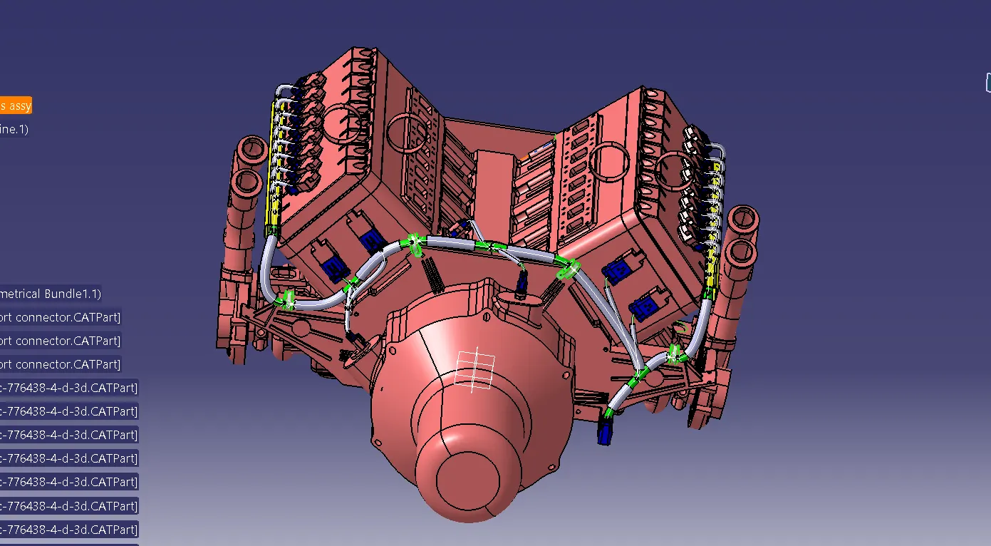
PVC tapping, cotton tapping are used in the wiring harness bundle as shown below.
Checking Bubdle Continuity:-
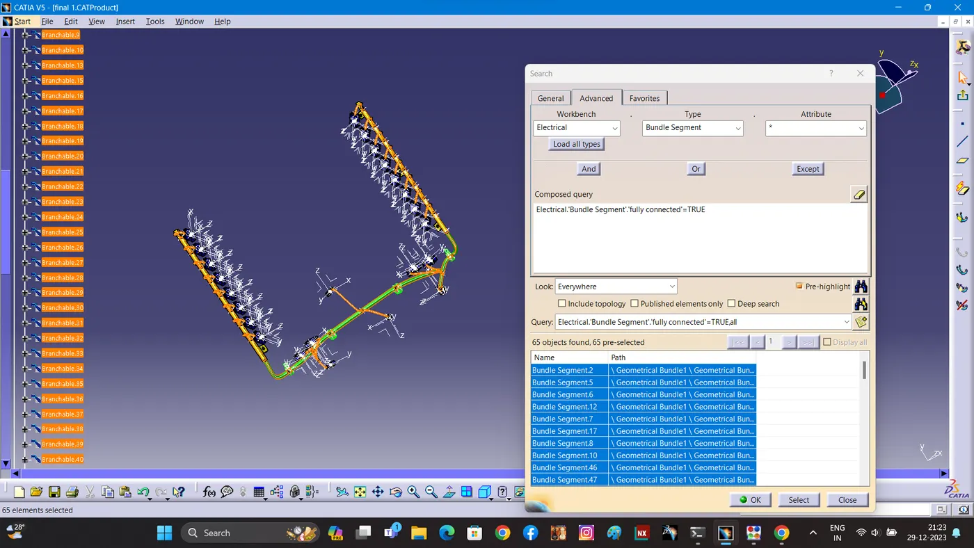
First, we have to make sure that multi branchable is selected and then we have to go in WORKBENCH>TYPE-BUNDLE
EDIT>SEARCH>ADVANCED>ELECTRICAL
SEGMENT>ATTRIBUTE-FULLY CONNECTED
Selecting the "TRUE" option will show all the connected bundle segments while the selecting "FALSE" will show all the non-connected bundle segments.
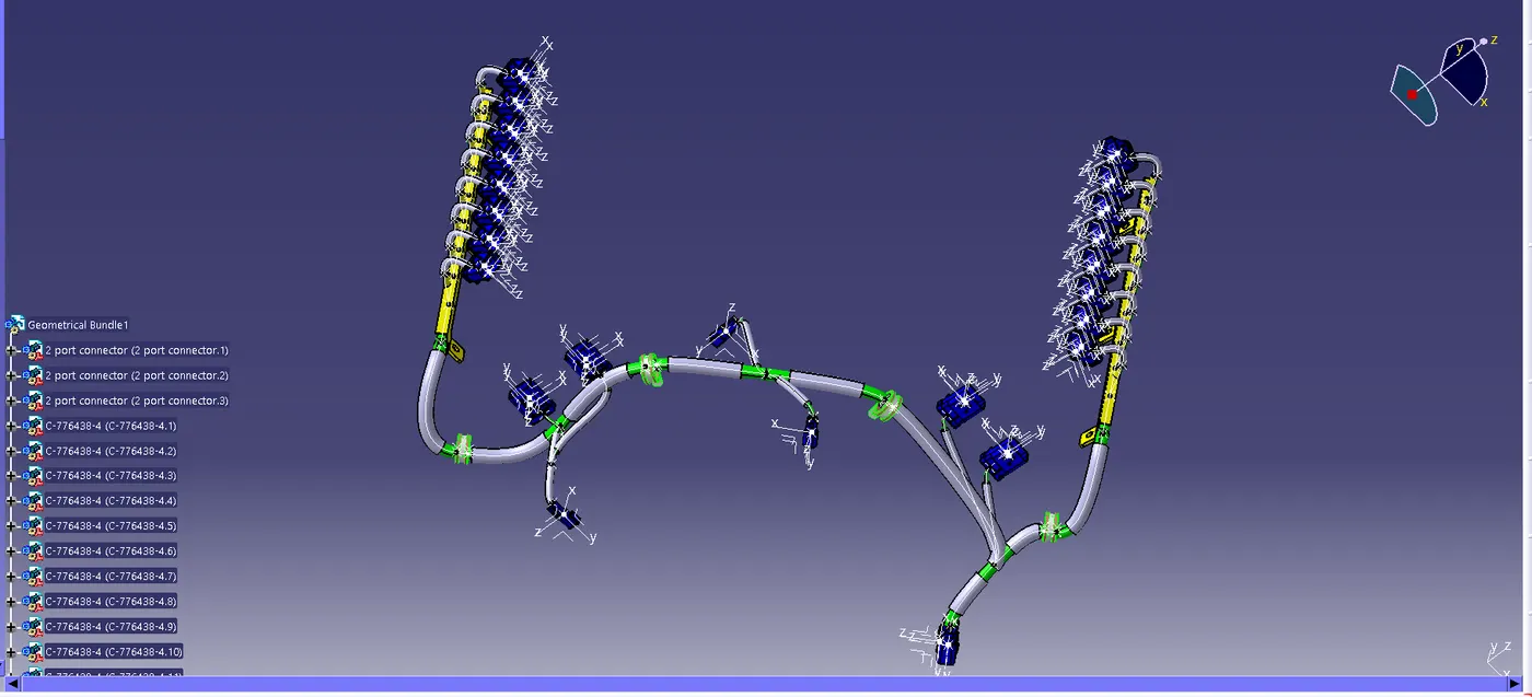
For now, we will select "TRUE" and search for results. All the bundle segments are highlighted and found showing that all the bundle segments are electrically connected.
OR
SIDE DOOR WIRING HARNESS ASSY
AIM:
Route the wire for the side door of a care with the necessary connector along with the guiding challenge data given
TASK:
- Routing assembly creation
- Flattening
- Drawing creation .
GIVEN:
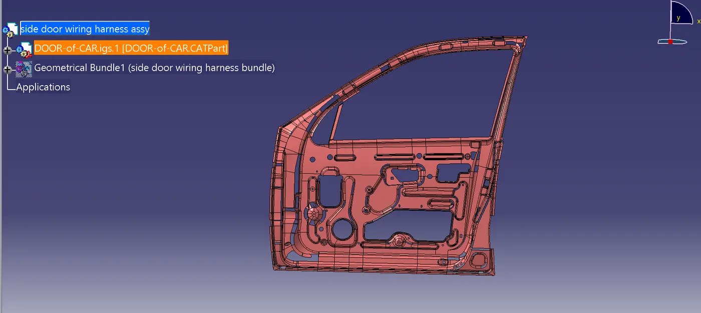
CREATE CONTEXT ASSEMBLY:
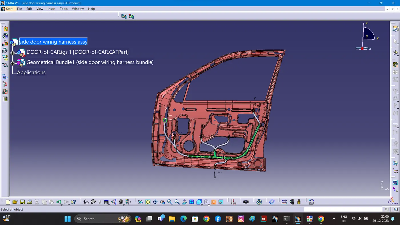
SAME THE BEND RATIO 1.4 AND LENGTH APROX 55MM FROM THE BUNDLE CONNECTION POINT.
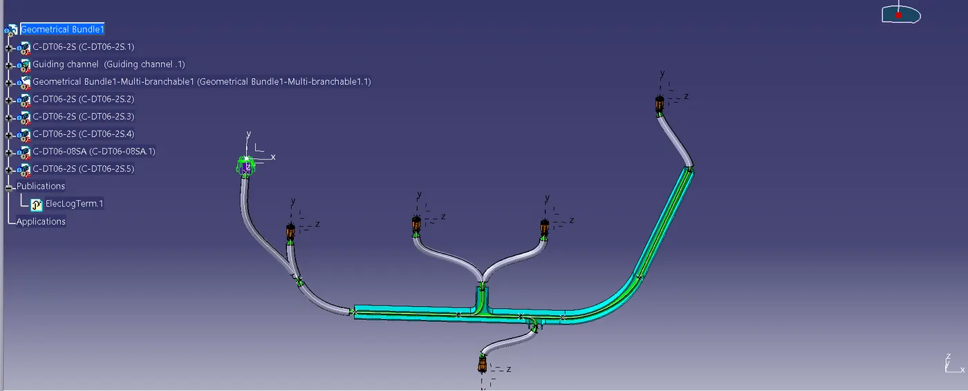
BUNDLE CONNECTION CHECK:
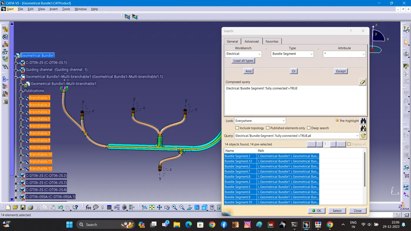
First, we have to make sure that multi branchable is selected and then we have to go in WORKBENCH>TYPE-BUNDLE
EDIT>SEARCH>ADVANCED>ELECTRICAL
SEGMENT>ATTRIBUTE-FULLY CONNECTED
Selecting the "TRUE" option will show all the connected bundle segments while the selecting "FALSE" will show all the non-connected bundle segments.
For now, we will select "TRUE" and search for results. All the bundle segments are highlighted and found showing that all the bundle segments are electrically connected.
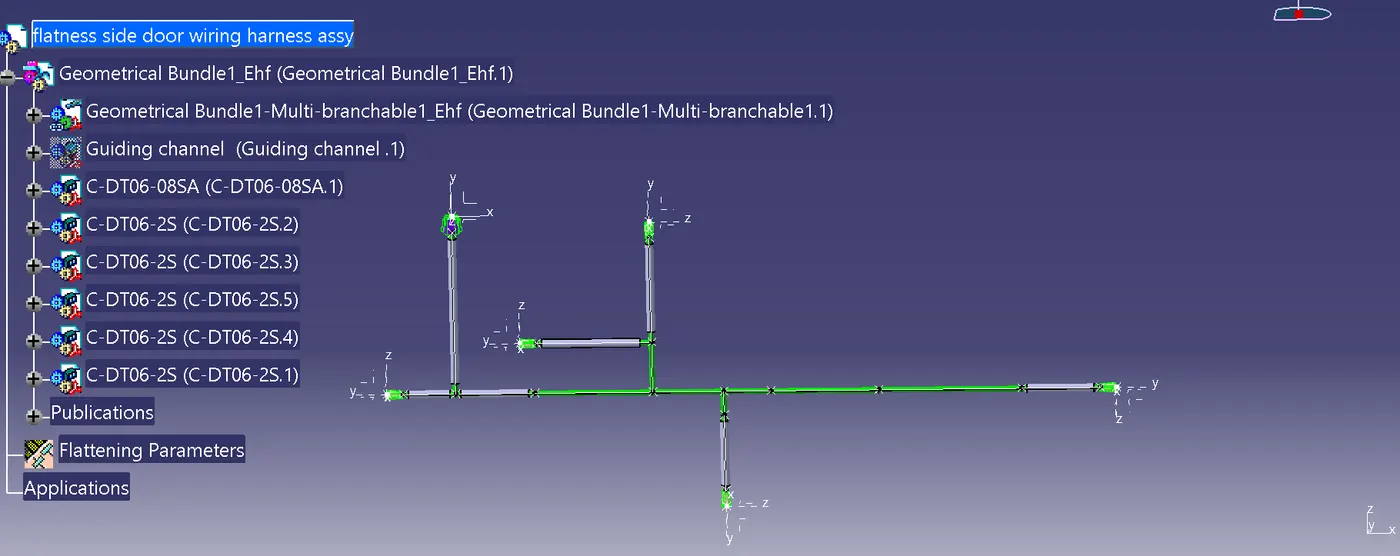
FLATNESS CREATION.
- At this stage, for clarity, we have been hidden the flattening diagram of the plastic guiding channels from the drawing view.
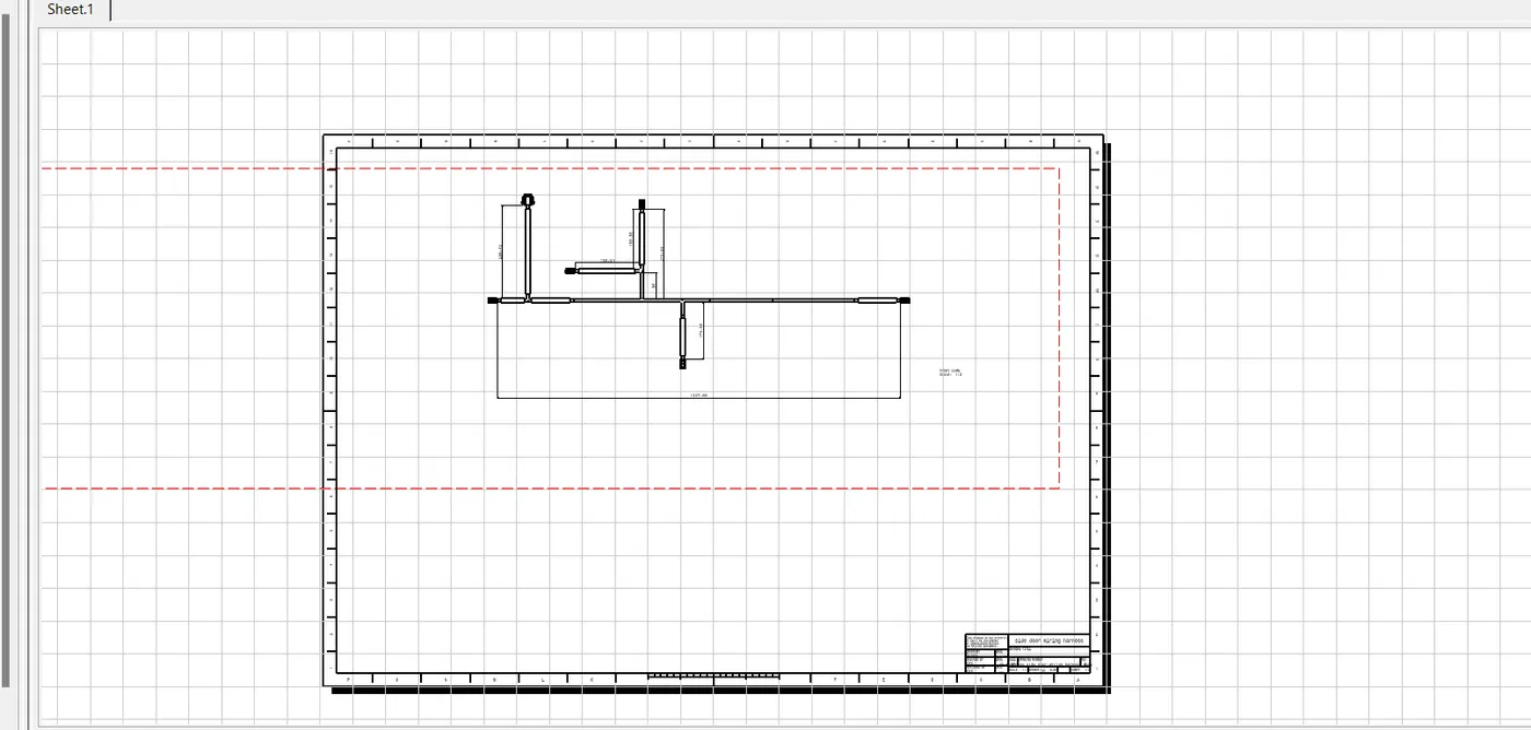
- DRAWING CREATION.
- we are creating new drawing file and defined all the necessary drawing parameters. We have to insert the front view of the Harness Flattening Product file into the Drawing file.
-
- Conclusion:
- In this way, we have routed wiring harness for the SIDE DOOR Also, prepared flatten view drawing with proper sheet in CATIA V5.
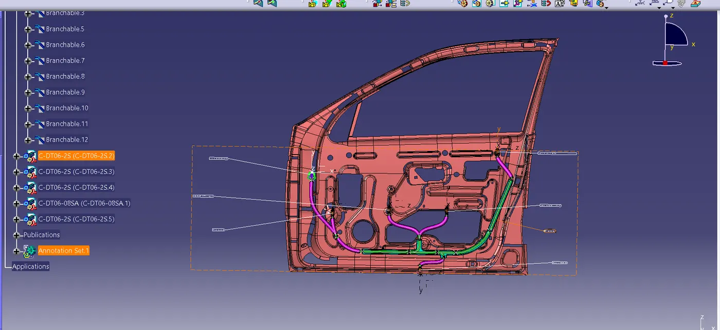
IN THE SIDE DOOR WIRING HARNESS ASSEMBLY I DID NOT USE ANY CLAMPING METOD BECAUSE THE MODERN CARS THE GUIDING CHANNEL REPRESENT ALL CLMPING PROCESS SO I AVOIDE IT.
(ERROR)
IN THE BUGATI ENGINE WIRING HARNESS ASSEMBLY I COMPLETE ALL BUNDLE CONNECTION WITH CONNECTOR. THEN DURING THE FLATNESS PROCESS THE GEOMETRIC DID NOT RENDER IN MY LAPTOP SO I COMPLETE OR CHOISE QUESTION.
(The Files Are Attached below in Zip format.(catalogue,cat,igs etc..,)