Project 1
PROJECT
AIM :
Develop a double-acting actuator model using Simscape Multibody and Simscape components.
OBJECTIVE :
The mechanical system of the cylinder needs to be built using Simscape Multibody library components/blocks, and the hydraulic system needs to be modeled using Simscape library physical components.
THEORY :
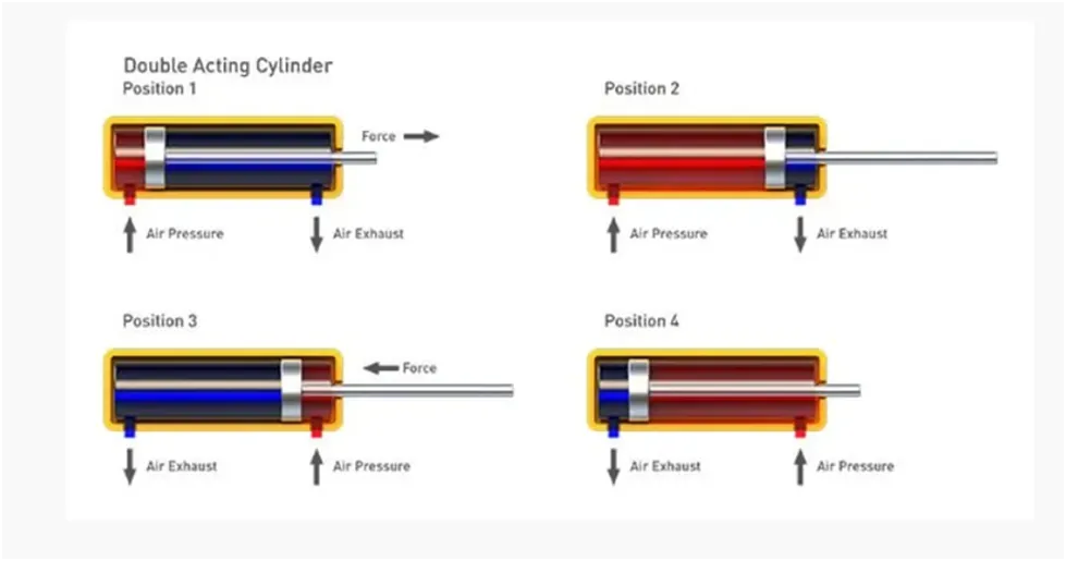
Double-acting actuators have air or liquid supplied to both sides of the piston with one side at higher pressure, which achieves the movement required to actuate the valve. This configuration uses pneumatic or hydraulic pressure of the air or liquid energy to open and close the valve.
Hence the term double acting actuator. This function utilizes two air/fluid supply ports integrated into the design of the housing.
One port allows air/fluid to access the chamber between the two pistons. Supplying sufficient air/fluid pressure here will force the pistons apart and rotate the pinion in one direction. The second port allows air/fluid to access the space on the opposing faces of the pistons. Supplying air/fluid pressure here, will push the pistons together and rotate the pinion in the opposite direction.
HYDRAULIC ACTUATORS:
Hydraulic actuators use liquid as a means to apply pressure to the actuator’s mechanical components. They can exert a large amount of force because liquid is not compressible but are generally limited in acceleration and speed. Hydraulic actuators are available in spring-return and double-acting designs.
DOUBLE-ACTING HYDRAULIC CYLINDER
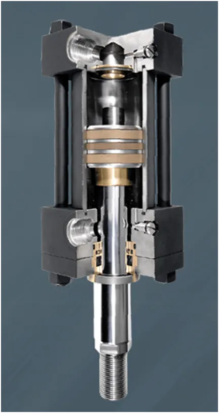
A mechanical device called a hydraulic cylinder uses hydraulic pressure to create pressure. They are frequently utilised in a variety of industrial applications as well as hydraulic pumps. They can be employed as actuators or lifting tools, among other things.
The mechanical device known as a double-acting hydraulic cylinder controls pressure by means of two chambers. The user can choose to selectively fill each chamber with pressurised fluid using control valves on each end of the device. As a result, the cylinder can be operated in one of two ways: either by pushing or drawing the lever in the same direction (which mimics the first action of a basic hydraulic cylinder), or by doing the opposite (resembling the second act of a simple hydraulic cylinder).
The cylinder will maintain pressure in one of the chambers in the event of a hydraulic failure until the oil supply is restored, preventing any damage or injuries. Two categories of double-acting cylinders exist:
- Double-acting cylinder with a piston rod on one side.
- Double-acting cylinder with a piston rod on both sides.
APPLICATIONS
- Industrial processes that need a rapid force frequently use double-acting hydraulic cylinders.
- Power steering is accomplished by double-acting cylinders, and the more potent the vehicle, the more power is required to steer it.
- This kind of cylinder is frequently seen in heavy-duty devices like cranes, forklifts, lifts, and other industrial machinery.
- Hydraulic systems that raise and lower items like landing gear, door hinges, etc. require double-acting cylinders.
- A double-acting hydraulic cylinder is frequently used to open or close a type of "flap" on an aeroplane wing.
WORKING
One chamber of a double-acting hydraulic cylinder is filled with oil, while the other is empty. Oil is forced into the empty chamber as the piston rod is withdrawn into the cylinder, creating pressure. The cylinder extends as a result of this pressure pushing the piston rod out. On the other side, a vacuum is produced when the piston rod is pressed into the cylinder and the oil is forced into the chamber that is already filled with oil. The piston rod retracts as a result of the vacuum pulling it into the cylinder. When the force is released in this way, the action is reversed. Double-acting hydraulic cylinders can be used to generate the necessary force to push or pull something.
Double-acting hydraulic cylinders perform two types of operations including:
- Differential types and
- Synchronous types.
DIFFERENTIAL TYPES HYDRAULIC CYLINDERS.
The most popular type of hydraulic cylinder is differential type. There are two pistons in it, one attached to the rod and the other to the body. The rod stretches as the input force rises. The second piston is locked into the cylinder at the same moment, keeping the body still. The output force rises as a result. The rod retracts when the input force lessens. The second piston is locked into the cylinder at the same moment, keeping the body still. The output force decreases as a result. As long as the input force and the output force are equal, the body will always stay in its starting position.
However, depending on whether of the two forces is greater, the rod will travel upward or downward. A hydraulic cylinder of the differential kind is therefore very helpful. For instance, you should utilise a rod attached to the cylinder's body to hoist a heavy box. A safety factor should be there to ensure that the rod's force is always greater than the weight of the thing being raised.
SYNCHRONOUS TYPES HYDRAULIC CYLINDERS.
Cylinders of the synchronous type operate on a different theory. An electrical signal is given to a valve, allowing oil to enter the cylinder and keep the piston moving up and down instead of oil pressure. When the signal is cut off, the piston comes to a stop and the oil stops pouring into the cylinder. As a result, the cylinder uses power quite effectively.
Hydraulic cylinders of the synchronous kind have just one piston. No matter how much hydraulic fluid is present in the cylinder, this piston will expand and compress simultaneously. This makes this kind of cylinder extremely effective but less potent than the other kind. This sort of hydraulic cylinder is typically utilised in automobiles, farms etc.
MECHANICAL SYSTEM MODEL OF DOUBLE ACTING ACTUATOR:
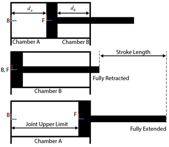
Here, we model the mechanical system of double acting actuator which is nothing but the cylinder with piston arrangement using the Simscape multibody blocks and library components.
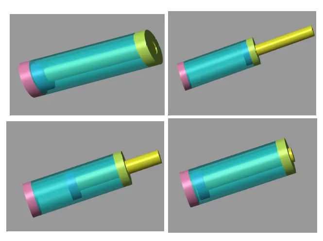
The schematics show the cylinder in three configurations: half-retracted, fully retracted, and fully extended.
Multibody Blocks:
1.Mechanism Configuration:
>The Mechanism Configuration block specifies the gravity and simulation parameters of the mechanism to which the block connects. The simulation parameters include the perturbation value for computing numerical partial derivatives during linearization and the iteration number for the joint mode transition.
2.Word Frame:
>This block represents the global reference frame in a model. This frame is inertial and at absolute rest. Rigidly connecting a frame to the World frame makes that frame inertial. Frame axes are orthogonal and arranged according to the right-hand rule.
>In a frame network, the World frame is the ultimate reference frame. Directly or indirectly, all other frames are defined with respect to the World frame. If multiple World Frame blocks connect to the same frame network, those blocks identify the same frame. If no World Frame block connects to a frame network, a copy of an existing frame, frozen in its initial position and orientation, serves as the World frame.
3.Joints:
a.Revolute Joint
>Represents a revolute joint acting between two frames. This joint has one rotational degree of freedom represented by one revolute primitive. The joint constrains the origins of the two frames to be coincident and the z-axes of the base and follower frames to be coincident, while the follower x-axis and y-axis can rotate around the z-axis.
>In the expandable nodes under Properties, specify the state, actuation method, sensing capabilities, and internal mechanics of the primitives of this joint. After you apply these settings, the block displays the corresponding physical signal ports.
b.Weld joint:
>This block represents a joint with zero degrees of freedom. It contains no joint primitives. Base and follower frames, each connected to a separate rigid body, are coincident for all time. The block dialog box provides sensing options for constraint and total forces and torques.
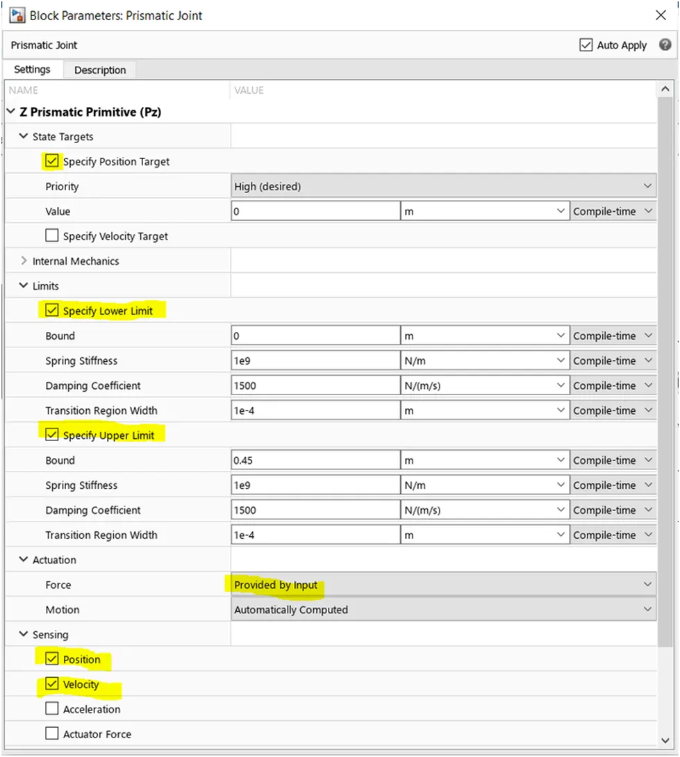
c.Prismatic joint
>The Prismatic Joint block has only one prismatic primitive, which is along the z-axis of the base frame. During simulation, the z-axes of the base and follower frames align, and the follower frame moves with respect to the base frame along the z-axis.
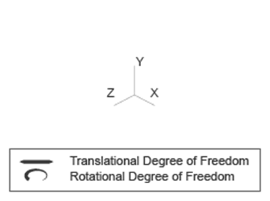
Joint Degrees of Freedom
4.Rigids:
>Defines a fixed 3-D rigid transformation between two frames. Two components independently specify the translational and rotational parts of the transformation. Different translations and rotations can be freely combined.
>In the expandable nodes under Properties, choose the type and parameters of the two transformation components.Ports B and F are frame ports that represent the base and follower frames, respectively. The transformation represents the follower frame origin and axis orientation in the base frame.
5.Solids:
a.Extruded Solid:
>Represents a solid combining a geometry, an inertia and mass, a graphics component, and rigidly attached frames into a single unit. A solid is the common building block of rigid bodies. The Solid block obtains the inertia from the geometry and density, from the geometry and mass, or from an inertia tensor that you specify.
>In the expandable nodes under Properties, select the types of geometry, inertia, graphic features, and frames that you want and their parameterizations.
b.Brick Solid:
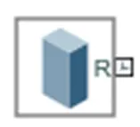
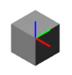
>The Brick Solid block is a prismatic shape with geometry center coincident with the reference frame origin and prismatic surfaces normal to the reference frame x, y, and z axes.
>The Brick Solid block adds to the attached frame a solid element with geometry, inertia, and color. The brick solid element can be a simple rigid body or part of a compound rigid body—a group of rigidly connected solids, often separated in space through rigid transformations.
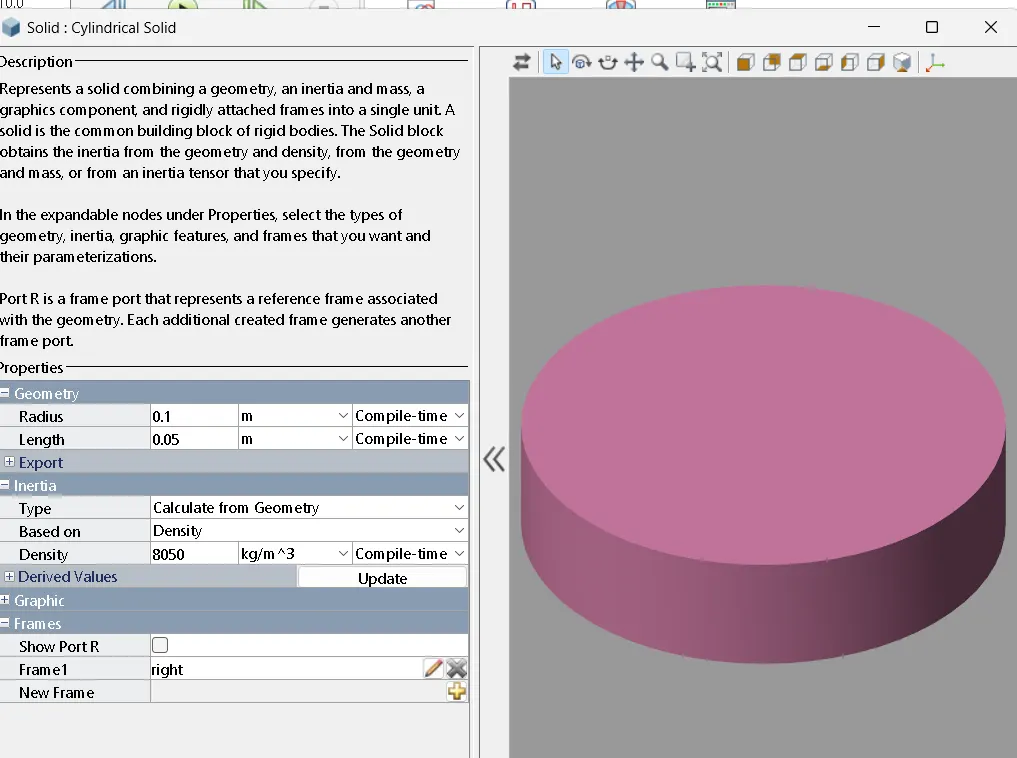
c.Cylindrical Solid:
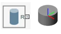
>Represents a solid combining a geometry, an inertia and mass, a graphics component, and rigidly attached frames into a single unit. A solid is the common building block of rigid bodies. The Solid block obtains the inertia from the geometry and density, from the geometry and mass, or from an inertia tensor that you specify.
>In the expandable nodes under Properties, select the types of geometry, inertia, graphic features, and frames that you want and their parameterizations.
d.Spherical solid:
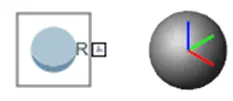
>The Spherical Solid block adds to the attached frame a solid element with geometry, inertia, and color. The solid element can be a simple rigid body or part of a compound rigid body—a group of rigidly connected solids, often separated in space through rigid transformations.
>Geometry parameters include shape and size. You can choose from a list of preset shapes or import a custom shape from an external file in STL or STEP format. By default, for all but STL-derived shapes, the block automatically computes the mass properties of the solid from the specified geometry and either mass or mass density.
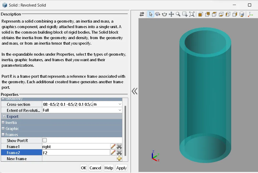
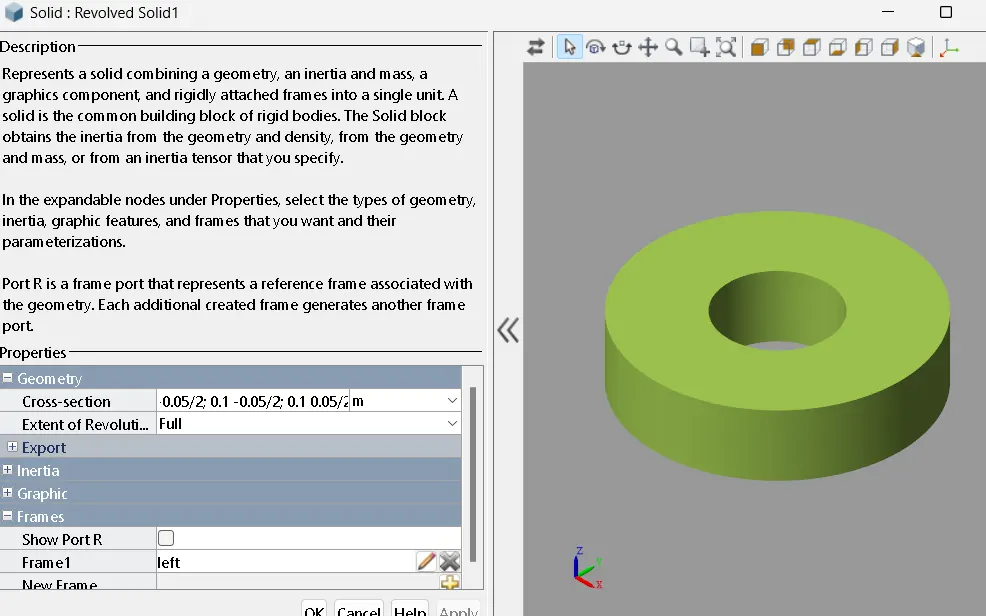
e.Revolved Solid:
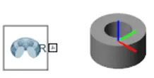
>The Revolved Solid block adds to the attached frame a solid element with geometry, inertia, and color. The solid element can be a simple rigid body or part of a compound rigid body—a group of rigidly connected solids, often separated in space through rigid transformations.
>Geometry parameters include shape and size. You can choose from a list of preset shapes or import a custom shape from an external file in STL or STEP format. By default, for all but STL-derived shapes, the block automatically computes the mass properties of the solid from the specified geometry and either mass or mass density
Translational Multibody interface:
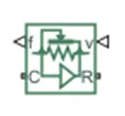
>The Translational Multibody Interface block implements an intuitive way to connect Simscape™ blocks that have mechanical translational ports with Simscape Multibod joints that have prismatic primitives. Simscape blocks that can be connected to a Translational Multibody Interface block,
The Translational Multibody Interface block matches the force and relative velocity across the interface. You can connect it to any Simscape Multibody joint that has a prismatic primitive:
- Enable the velocity sensing port v and the force actuation port f on the joint. If the joint has multiple degrees of freedom, make sure that the selected velocity sensing and force actuation correspond to the same degree of freedom.
- Connect physical signal ports v and f of the Translational Multibody Interface block to ports v and f of the Simscape Multibody joint.
- Connect ports C and R of the Translational Multibody Interface block to a Simscape mechanical translational network.
Building the mechanical system of the cylinder using Simscape Multibody library components/blocks.
- To model the cylinder and piston, you can use the Revolved Solid (Simscape Multibody) and Cylindrical Solid (Simscape Multibody) blocks.
- To provide the translational degree of freedom for the piston, use a Prismatic Joint (Simscape Multibody) block.
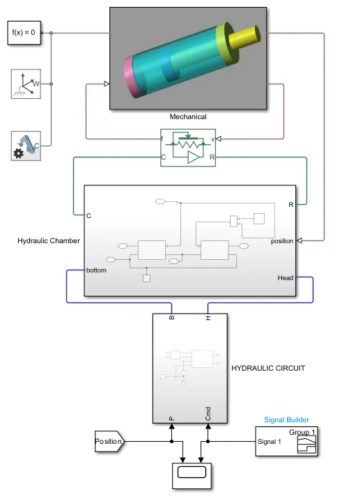
MECHANICAL :
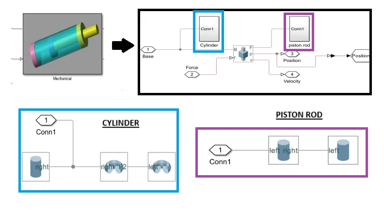
BULID CYLINDER
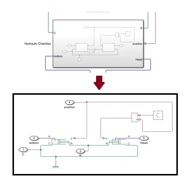
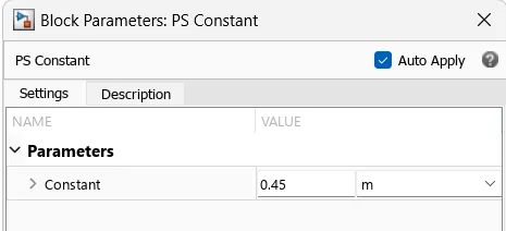
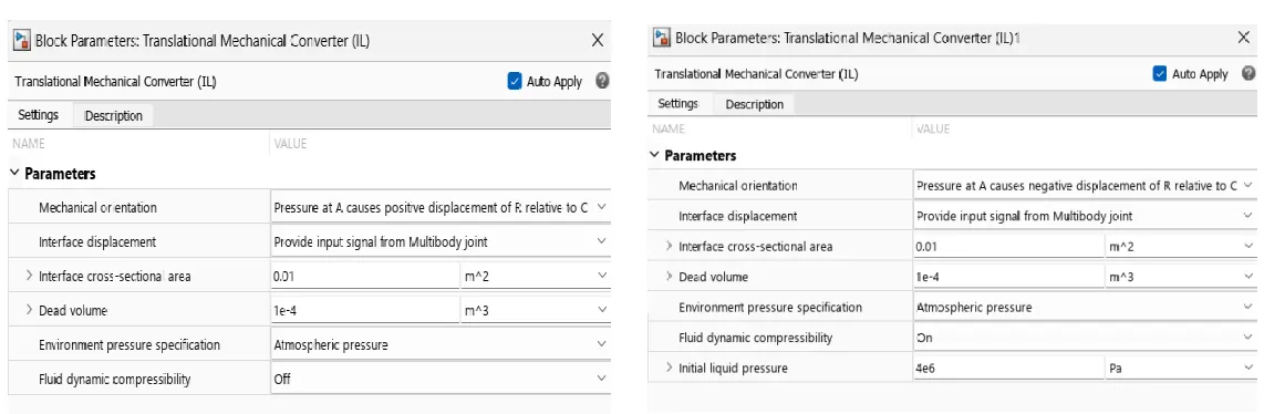
HYDRAULIC CHAMBER
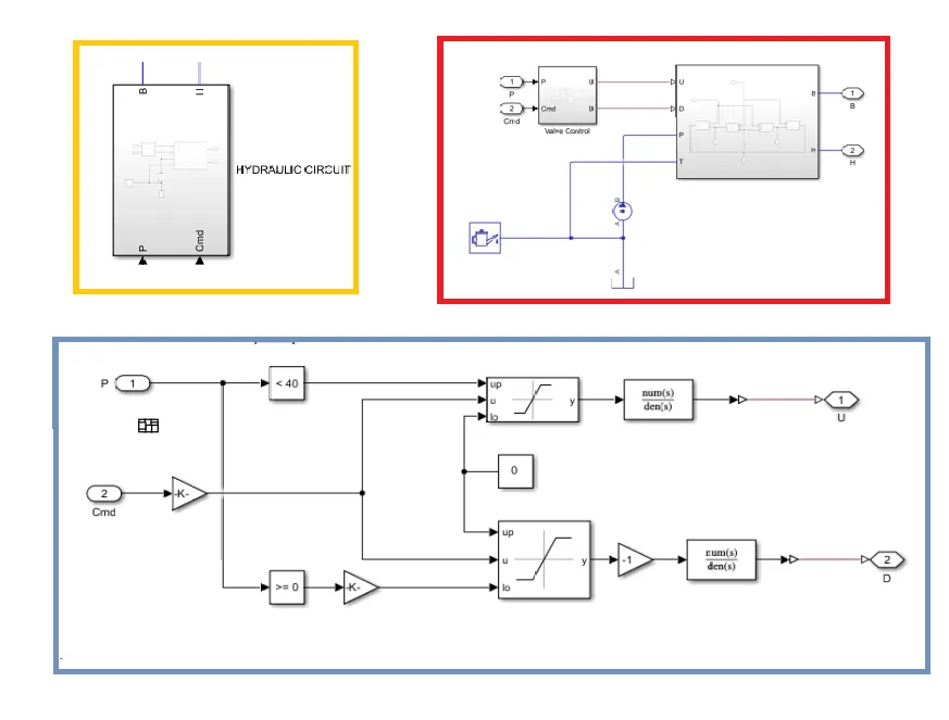
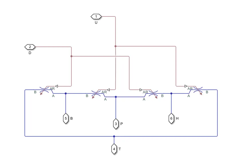
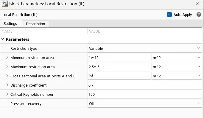
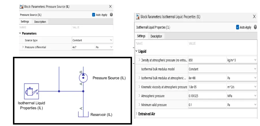
HYDRAULIC CIRCUIT
INPUT
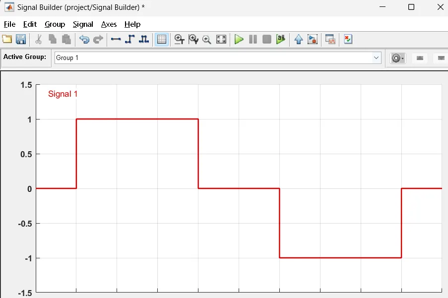
RESULT