Project 1
PROJECT 1
Download the Engine Cad Data and Required Connectors CAD data from the given Source.
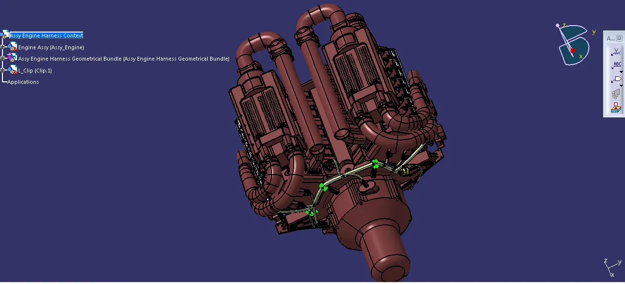
Download the required Connectors from the Source and Convert the Mechanical Connectors electrically by using the electrical part design work bench by following below steps.
First download the Connectors and mounting clip from the given link source.
Get into Mechanical part workbench to create required geometrical parameters. Create Connector Connection point and bundle connection point on the required sides of the CAD part.
Create axis system on the Connector Connection point Such a Way that the Y Coordinate facing normal to the connector face, X co-ordinate facing towards the locking mechanism and Z Co-ordinates facing to the top.
Create Cavity Connection Point for Connectors having the cavity for mounting clips.
Using the geometrical parameters Created.
Define part as electrical connector.
Define bundle connection point.
Define connector connection point.
Define Cavity Connection Point.
4 pole connector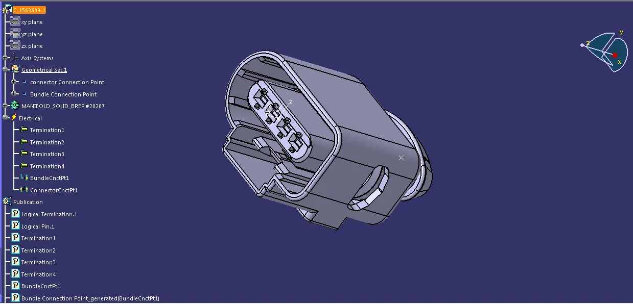
2 Pole connector
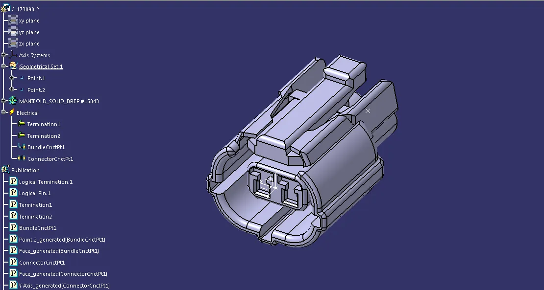
2 Pole Connector
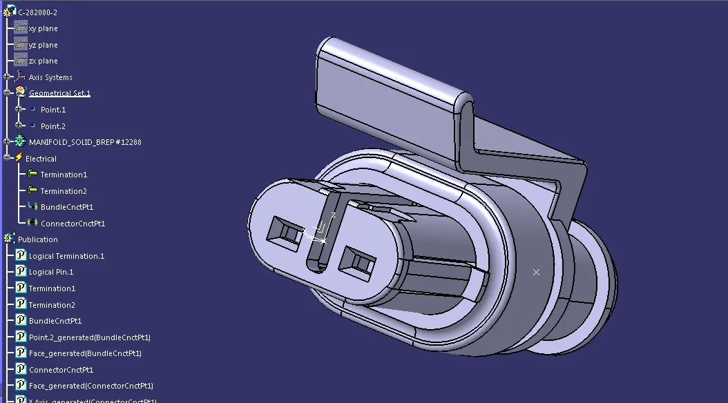
Creating the Context assembly
Context assembly is nothing but the product file which contains the engine 3D-CAD data and the engine harness geometrical bundle. Here the geometrical bundle product contains all the connectors and other mounting equipments, clips and clamps which are electrically defined for the assembly. Sheet metal L-clamp are added in the main context assembly. Then we need to switch into the Electrical Harness Assembly workbench and Geometrical Bundle Product file should be eelectrically defined using the Define Geometrical Bundle Option before adding any parts into it.
Adding 4 pole connectors to all fuel injector sensors as well as for the camshaft sensors.
4 pole connectors connectors should be added in the geometrical bundle using copy and paste connector. Connectors can be added again by copy pasting the 1 st imported connector.Place the Connectors on all the fuel injector sensors and cam-shaft sensors using the manipulation tools like move, smart move, snap tool and also using the compass.
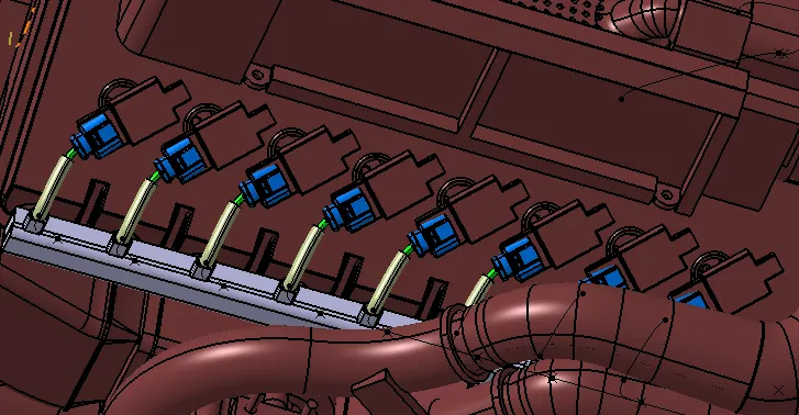
Placing the Interconnection connector and L-clamp Support
However, Situation of interconnection connectors are not similar to device connectors. Interconnection connectors are not parked with any device but should be parked with the Help of clips/clamps/ Sheet metal Bracket etc. Possible to the Packaging conditions.
Un parked Connectors Can Create Following Issues :-
Rattling Noise.
Physical damage to Connectors.
Uncontrolled Harness Routing.
Manual errors during assembly because of undefined parking.
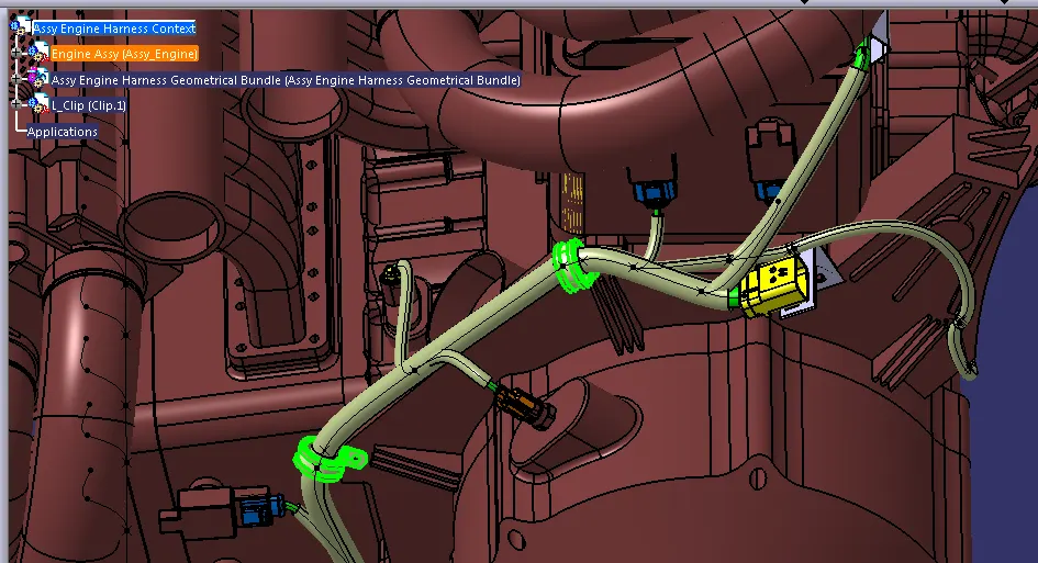
Add P-clamps for proper Routing of the harness Bundle.
Adding supporting components like p-clamps and firtree clip Can help the harness bundle provide proper routing and also help to prevent the Harness bundles fouling from unwanted mechanical components.
P- clamp and the Fir Tree can be placed at required locations to ensure best possible routing for the Harness Bundles.
The p-clamp can be mounted to the holes provided on the Engine Block in which the Screws to tighten the Engine Block.
Harness Routing Procedure for the channel
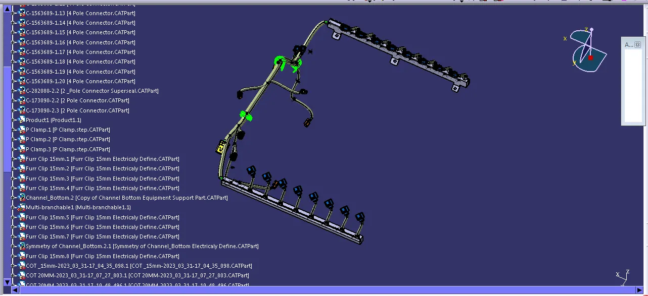
First, We need to create multi branchable bundle using the External curve option and select the line which we created earlier.
After Creating Bundle Segment Create 8 Branch points inside the Channel for Creating sub Branches for the injector sensor connectors.
Wiring Harness Flattening :-
Wiring Harness Bundle Packaging Process is done. Now we need to convert the geometrical bundle into a flattened wiring harness in the electrical Harness Flattening Workbench .
To create the Flattened Harness , We need to create a new Product file and switch into electrical Harness flattening Parameters and then Extract the geometric bundle from the Wiring Harness Context product file.
Then Select all the Branches and Flatten the entire Geometric Bundle.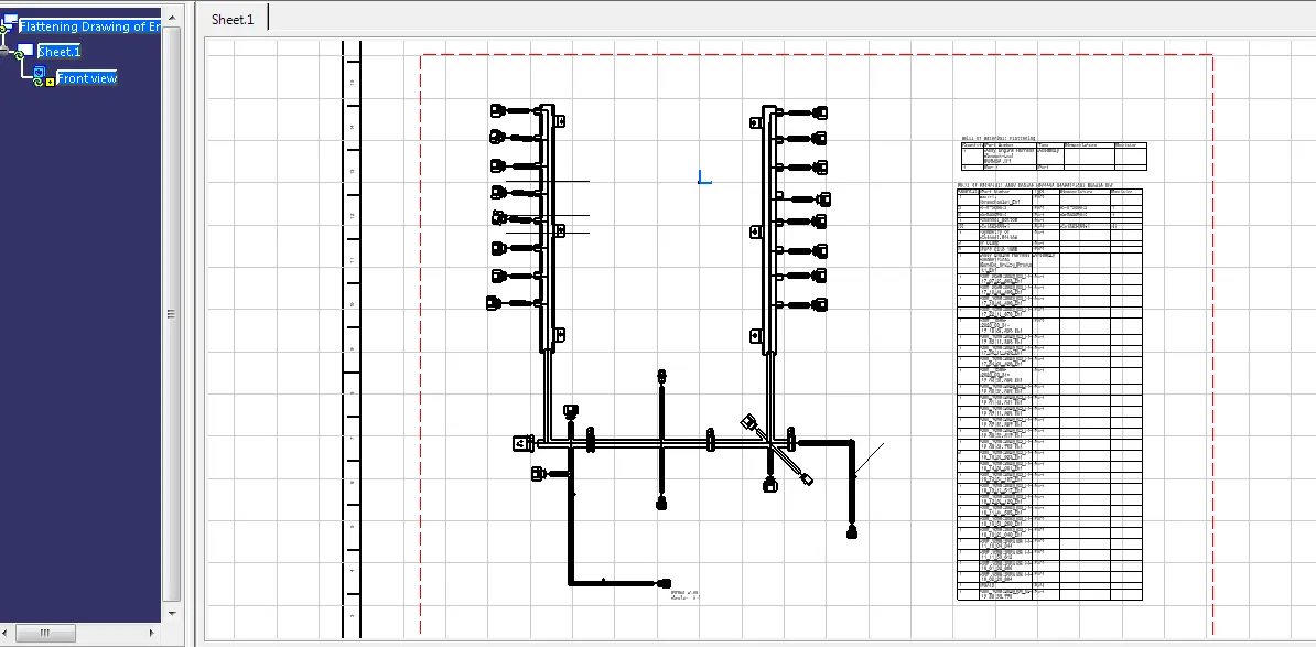
Project 1 Link
https://drive.google.com/file/d/1QEVJmRfQFsmLMxKvmXBrxs_QiQ_lotlv/view?usp=sharing
The file was not getting upload. So, I attached the Drive link.