Project 1
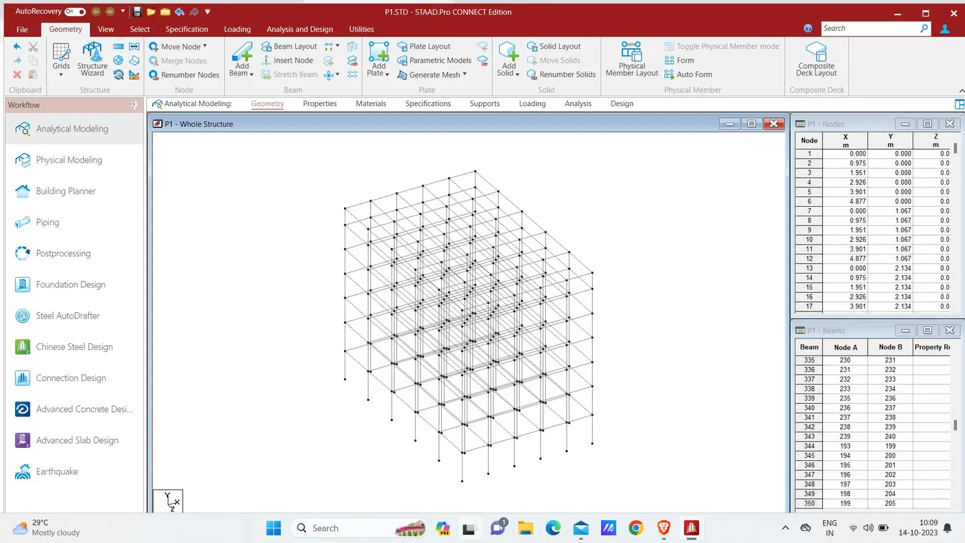
1. Design a multi-storey Residential Building located in Bangalore using STAAD Pro Connect Edition. The specification must be as follows:
|
Building floors |
G + 6 + R |
|
Plan dimension |
B = 25m , L = 16m |
|
Storey Height |
h = 3.5m |
|
Soil |
Hard soil |
|
Use |
Residential Purpose |
|
Safe Bearing Capacity |
180 kN/m2 |
|
Maximum slab thickness |
150mm |
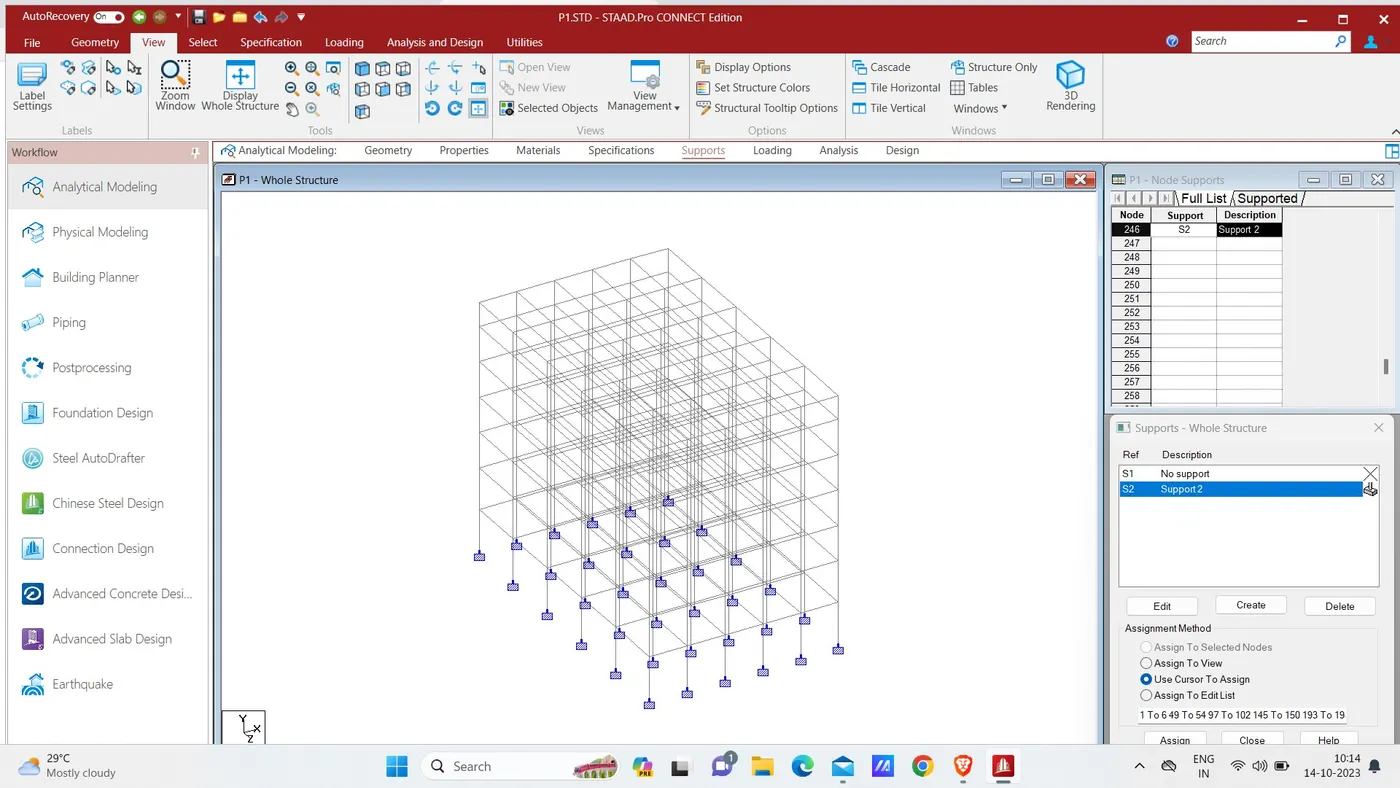
Assume suitable sections for structural elements. Follow IS456, IS1893 and IS 875
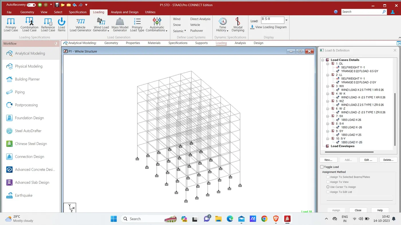
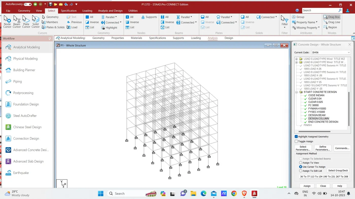
Material specifications :
Assuming the size of beams = 300mmX400mm
Assuming size of columns = 300mX400mm
Assuming thickness of slab as 150mm
Load calculations:
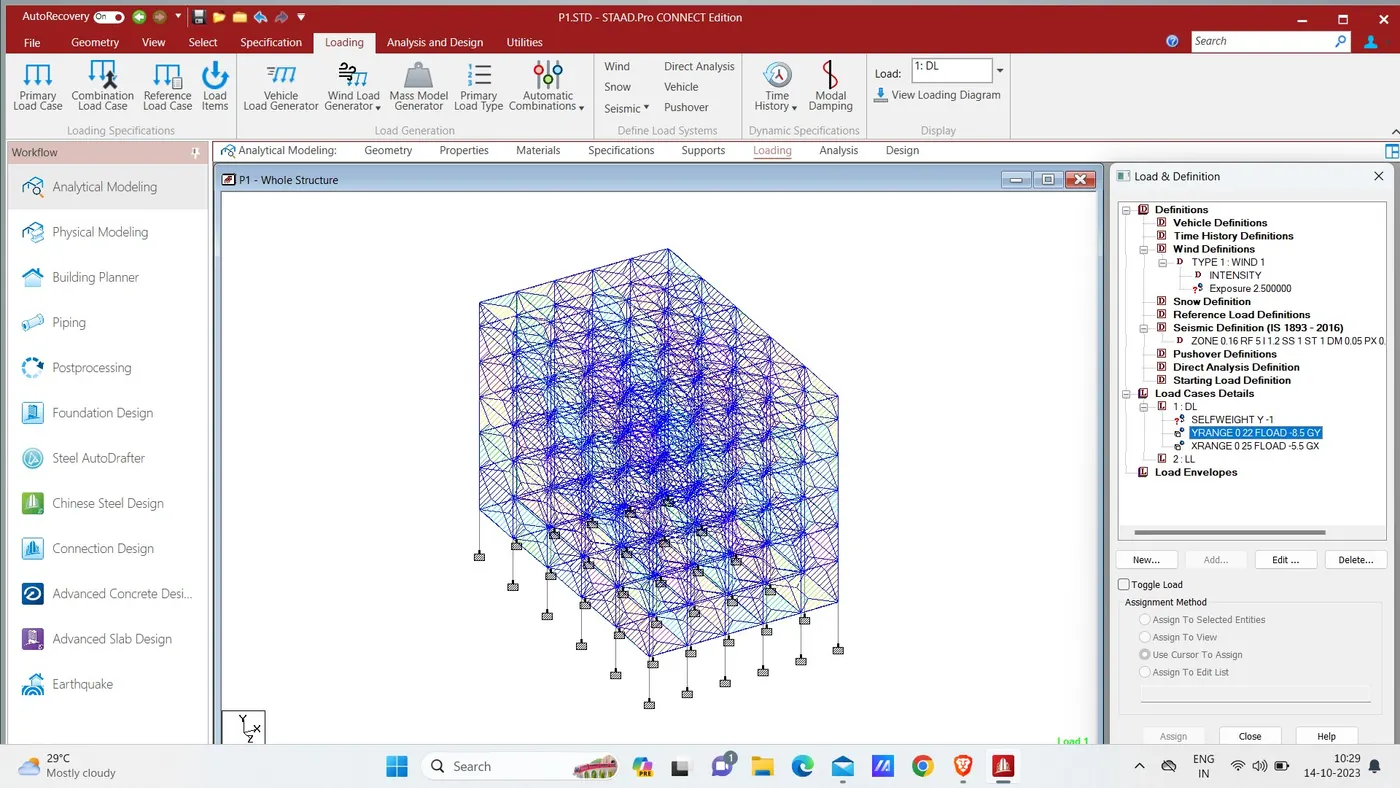
(1) Dead loads:
(a) Dead load on floor :
- Dead weight due to slab = 0.15 x 25 = 3.75kN/sqm
- Partitions = 1.5kN/sqm
- Floor finish = 2.5kN/sqm
- Miscellaneous = 1kN/sqm
- Total floor load = 8.75kN/sqm
(b) Dead load on roof:
- Dead load on roof slab = 3.75kN/sqm
- Insulation and water proofing = 0.5kN/sqm
- MEP services = 0.5kN/sqm
- Miscellaneous = 0.5kN/sqm
- Total roof load = 5.25kN/sqm
(2) Live load :
(a) For residential bilding live load for a floor is 3kN/sqm
(b) For roof the live load is 1.5kN/sqm
(c) Wind load calculation as per IS875 part-111
Design wind spedd
we know that
Vz=Vbxk1xk2xk3xk4
Where,
Vb is basic wind speed (m/s)
k1 is reisk coefficent (IS 875 part-111 Table -1)
k2 is terrain roughness and height factor
k3 is topograhpy factor (IS 875 part-111 Clause 6.3.3)
k4 is importance factor for cyclic region
Vb = 33m/s ,for Bangalore (as per IS875 part-111)
k1 = 1
k2 = 1.15 (for height of 23m)
k3 = 1
k4 = 1
therefore , Vb = 33x1x1.15x1x1
Vb = 37.95m/s
Wind pressure (Pz) :
Pz = 0.6x (Vz)^2
Pz = 0.6 x (3.795)^2
Pz = 864.121N
Pz = 0.864kN
Similarly, we can calculate the wind pressure for different heights like below
| Height (m) | k1 | k2 | k3 | k4 | Vz | Pz | Pz in kN |
| 3.5 | 1 | 1.05 | 1 | 1 | 34.65 | 720.37 | 0.72 |
| 7 | 1 | 1.05 | 1 | 1 | 34.65 | 720.37 | 0.72 |
| 10.5 | 1 | 1.06 | 1 | 1 | 35.2 | 743.42 | 0.74 |
| 14 | 1 | 1.08 | 1 | 1 | 35.64 | 762.12 | 0.76 |
| 17.5 | 1 | 1.1 | 1 | 1 | 36.3 | 790.61 | 0.79 |
| 21 | 1 | 1.125 | 1 | 1 | 37.13 | 827.18 | 0.83 |
| 24.5 | 1 | 1.13 | 1 | 1 | 37.29 | 834.32 | 0.83 |
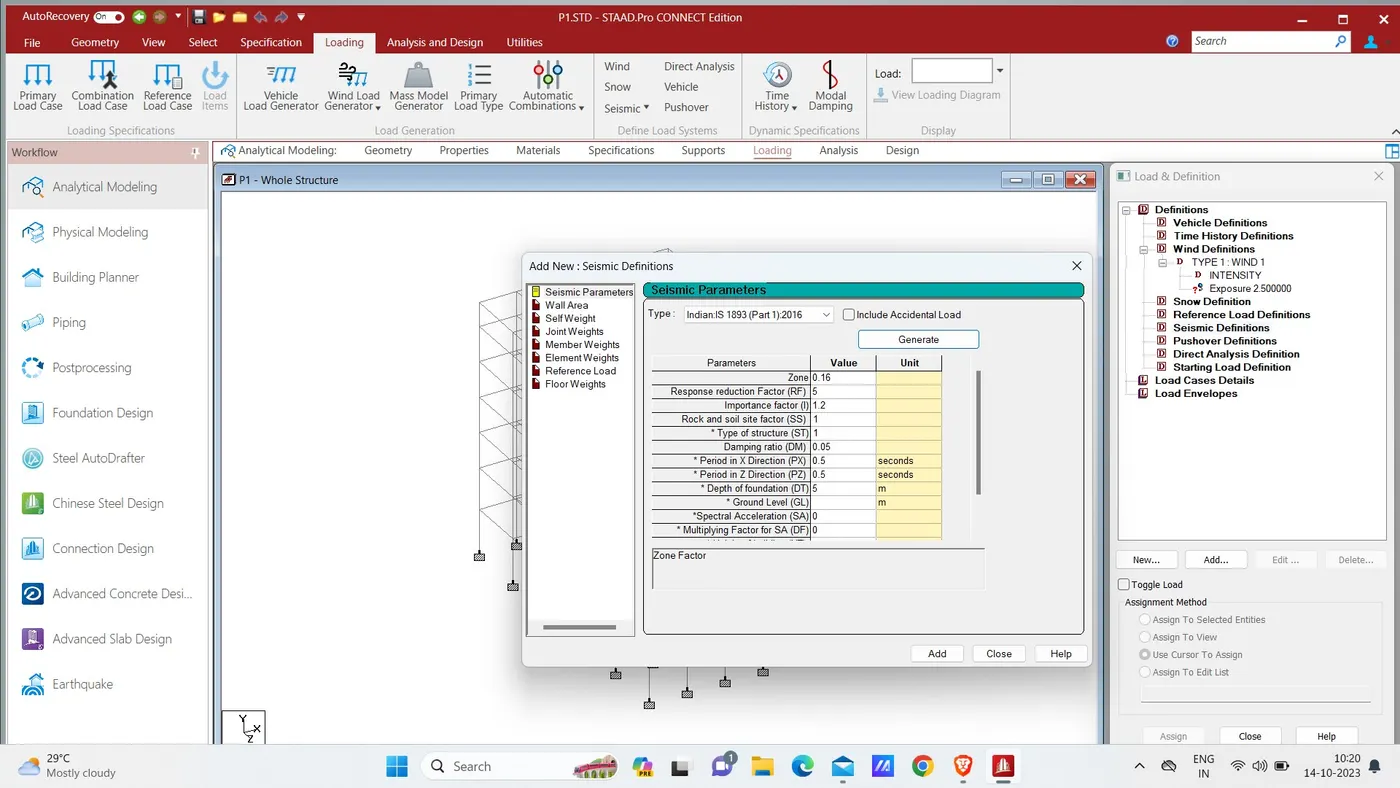
(d) Seismic load :
Design base shear :
Vb =Ah x W
where,
Ah = Horizontal coefficient of accelaration
W = seismic weight
As we know that Ah can be calculated by formula
so, as the given location is bangalore
Seismic zone(Z) = Zone ii
Soil type(Sa) = Hard soil
Importance factor = 1 for residential building
Response reduction factor = 5
Calculation of Sa/g (design accelaration co-efficient for different soil types :
where,
h = height of the building
d = base dimension of the building at the plinth level along the consideration direction of earthquake shaking in m
Along X direction
Tx =0.09x23/4
T = 0.52 s
Along Z direction
Tz = 0.09x23/5
T = 0.41 s
Considerting the maximum time period, T = 0.52 s.
According to the IS code for hard soil whose T valueis between 0.4s to 4s , the value for Sa/g = 1.47
Sa/g = 1/T = 1.47
For reduction factor (R)
R = 5
I is importance factor, I = 1
Now, Ah = (0.1/2) x 1.47 x (1/5)
Ah = 0.0147
Seismic weight of building :
- Dead and live load calculations for all floors
area of each floor = 16x25 = 400sqm
- Typical floor weight due to dead load
DL = 8.75KN/sqm
so total dead load for each floor = 8.75 x 400 = 3500kn
DL due to roof = 5.25 x 400 = 2100kN
- Due to live load
floor load LL = 3kN/sqm, which is reduced by 50% due to addition of seismic load
LL = 1.5kN/sqm
Total LL for all the floors = 1.5 x 400 = 600kN
LL for roof is neglected according to IS code
- Total seismic weight W = Dl + LL + DL of roof
(3500+600)x6 + 2100 = 26766kN
Design base shear :
Ah = 0.0147
W = 26766kN
Design base shear Vb = 0.0147x26766
Vb = 393.46 kN
lateral force at different levels :
Formula according to IS code
| storey level | wi | hi | wihi2 | ki | Lateral force(Qx) | Lateral force (Qz) |
| Roof | 2100 | 23 | 1110900 | 0.19 | 74.76 | 74.76 |
| fifth floor | 4100 | 21 | 1808100 | 0.31 | 121.98 | 121.98 |
| fourth floor | 4100 | 17.5 | 1255625 | 0.22 | 86.56 | 86.56 |
| third floor | 4100 | 14 | 803600 | 0.14 | 55.08 | 55.08 |
| second floor | 4100 | 10.5 | 452025 | 0.07 | 27.55 | 27.55 |
| first floor | 4100 | 7 | 323900 | 0.06 | 23.61 | 23.61 |
| ground floor | 4100 | 3.5 | 50225 | 0.009 | 3.54 | 3.54 |
| 5804375 | 393.46 | 393.46 |
Design of slab element using MS-excel
Bar bending schedule for beams
- A step by step procedure for Beam design in RCDC has been shown with the help of pictures below
- After analysing the structure, goto advanced concrete design which is present at the left side under workflow tab
- Select RCDC and selecr beams for a level
- Click on create project after giving it a name
- Now, RCDC takes all the required information from STAAD pro
- Noe, goto settings and give all the required settings such as grade of steel and concreet, clear cover etc
- Now, goto design tab and click on design
- A detailed design of beams can be seen and all the failed beams are shown with a red mark
- Calculations and others can be extracted from Reports tab
- Bar bending schedule can be extracted from BBS tab
- There were some failed beams in the structure
- So the dimensions are changed to make the structure pass the forces applied
- Revised structure is analised and the same procedure as shown above is perfoemed once again and BBS of all passed beams have been extracted.
Bar bending schedule for columns
- A step by step procedure for column design in RCDC has been shown with the help of pictures below
- After analysing the structure, goto advanced concrete design which is present at the left side under workflow tab
- Select RCDC and select columns and walls
- Click on create project after giving it a name
- Now, RCDC takes all the required information from STAAD pro
- Noe, goto settings and give all the required settings such as grade of steel and concreet, clear cover etc
- Now, goto design tab and click on design
- A detailed design of columns can be seen and all the failed columns are shown with a red mark
- Calculations and others can be extracted from Reports tab
- Bar bending schedule can be extracted from BBS tab
Design of foundations using STAAD pro
- A step by step procedure for foundation design in STAAD pro has been shown with the help of pictures below
- After analysing the structure, goto foundation design which is present at the left side under workflow tab
- Select RCDC and select columns and walls
- Now, foundation design connect takes all the required information from STAAD pro
- Now, goto units and change tothe required units and give all the required specifications such as grade of steel and concreet, clear cover etc
- Now, goto design in the main navigator bar present at the left side of the screen
- A detailed design of foundation can be seen
- Detailed and schedule drawings, General arrangement drawing and calculation sheets can be extracted from the tab above the working screen
Result :
A residential building of G+6+R has been designed successfully using STAAD pro, RCDC and STAAD foundation connect and all the reports such as calculations are added in the documents section including the STAAD pro file.