Project 1
PROJECT-1 V16 ENGINE WIRING HARNESS DESIGN
Aim:
To Route the Wiring harness on Given Engine and Prepare a flattened view drawing in CATIA V5. Application of all Packaging rules, Industry best practices studied in this course shall be demonstrated in design. Apply Protection coverings as required.
EXPLANATION OF WIRING HARNESS IN ENGINE:
Definition:
The wiring harness is the combination of electrical cables, or assembly of wires, that connects all electrical and electronic (E/E) components in the automotive vehicle, like sensors, electronic control units, batteries, and actuators. The wiring harness handles the energy and information flow within the E/E system to fulfill primary car functions, such as steering and braking as well as secondary car functions, such as ventilation and infotainment.
WHAT IS AN ENGINE WIRING HARNESS?
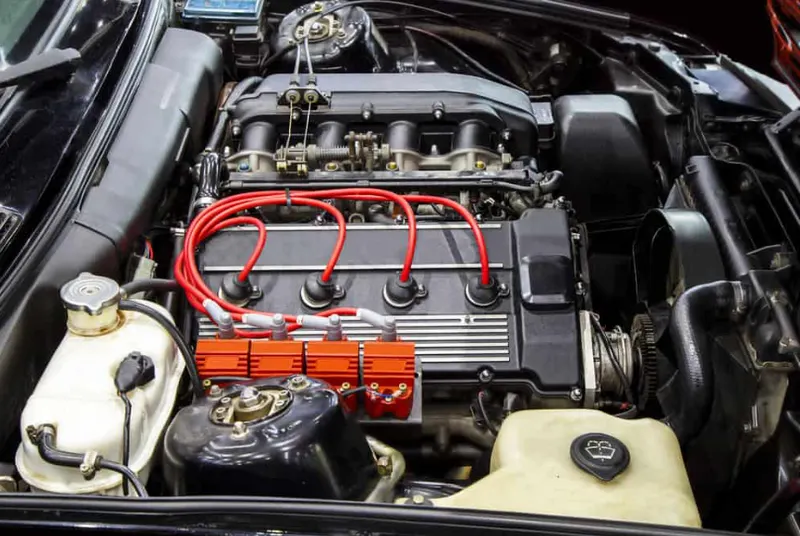
An engine wiring harness is constricted wires, cables, terminals, and connectors controlling a vehicle’s electrical system. It relays electrical power and control information to components such as batteries, alternators, fuel injectors, fuses, audio systems, blower motors, fuel injectors, and computers. Wire harness companies customize it for every location, application, and design it interconnects.
Also known as a cable harness, it is more than just a collection of multiple wires put together.
The harness also reduces the likelihood of electrical problems that would otherwise affect the vehicle or equipment. Flame retardant over molding minimizes the risk of electrical fires. Also, It shields cables and wires from moisture, thus preventing corrosion. In addition, by installing the harness on the vehicle or machinery’s frame or chassis, there is a lower likelihood of damage from abrasions and vibration.
Types of wiring Harnesses:
There are different types of vehicle wiring harnesses, including:
- Airbag Harness – Controls the opening of the airbag in the vehicle.
- Main Harness – Controls instruments, control panel, guidance system, multimedia, and electronic equipment. Forms part of the chassis wiring harness together with the front and rear harnesses.
- Engine Harness – Manages the key functions around the engine including engine controller, oil controller gate, transmission plug housing, air pipe sensors, pressure sensors, and water temperature sensors.
- Body Wiring Harness (or Body Harness or Floor Harness) – Keeps the air conditioning system, back sonar, navigation, dimmer switches, and speakers functioning.
- Battery Harness – Delivers the main power to the other units. Serves as a connecting bridge between the engine and other vehicle components.
- Door Wiring Harness – Found in car doors. Controls door and window lock, door and window power, and the speaker.
- Roof Harness – Located in the car’s roof and controls roof features, including the sunroof.
- Front Wiring Harness – Forms part of the chassis wiring harness together with the main and rear harnesses. Controls air conditioner fan, cooler fan, power sensor, temperature sensor, pedal sensor, speed limit sensor, oxygen sensor, and more.
ENGINE WIRING HARNESS ROUTING:
Main engine harness objectives are given below:
- Define all the mechanical connectors electrically and save it in the Catalogue.
- Place all the connectors to the required positions on the given engine 3D CAD model
- Place P-Clamps and Fir Tree clips at the required position by following the packaging rules.
- Create the Wiring Harness Routing with all the electrically defined connectors and mounting equipments.
- Create branching points at required locations to create sub branches and connect to various connectors in the geometrical bundle.
- Apply Protection coverings as required.
- Create Wiring harness flattening for the final geometrical bundle.
- Using the drafting workbench, create a drawing sheet with the flattened wiring harness.
Given V16 Engine CAD file:
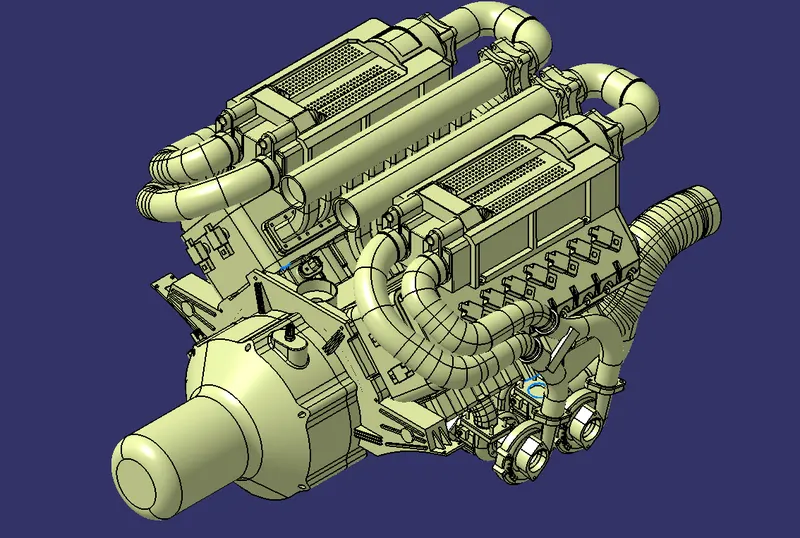
The above figure shows the given V16 engine cad data .Here routing the wiring harness for the following electrical components attached to the engine.
- fuel injector for each cylinder we have 16 cylinder engine
- camshaft sensors on each engine block (4 camshaft sensor )
- Engine coolant sensor at the centre of the engine between the two blocks
- Engine oil temperature and oil pressure sensor fitted at the oil sump of the engine on both engine cylinder blocks
- sensors for sense neutral positon of the transmission assembly and measure the vehicle speed
- Interconnection connector to connect engine harness system to vehicle harness system.
Harness mounting and routing management required to provide proper packaging of the wiring harness.it also deals with clearance management and manufacturability
- P-clamps to provide positive clamping and proper clearance management for the routing
- Mounting clips for connector mounting
- Guiding channels provide thermal protection in high temperature zones .
- Corrugated tubes used to protect the wiring harness from hazardous liquids and temperature
Next create a new product in assembly workbench named as assembly wiring harness contex .it is the top level product file inside this product file created geometrical bundle and wire harness electrical bundle.Given V16 engine cad data added inside this contex assembly.
Geometrical bundle contains all of the harness components i.e connectors ,clip, gromets and actual physical bundle segments and branches.All the components should be defined electrically .
Download the 3d data of required connectors and mountings from the site TE.com from given challenge CAD files links.
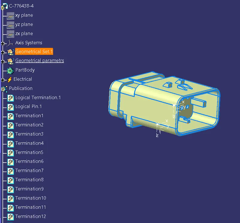
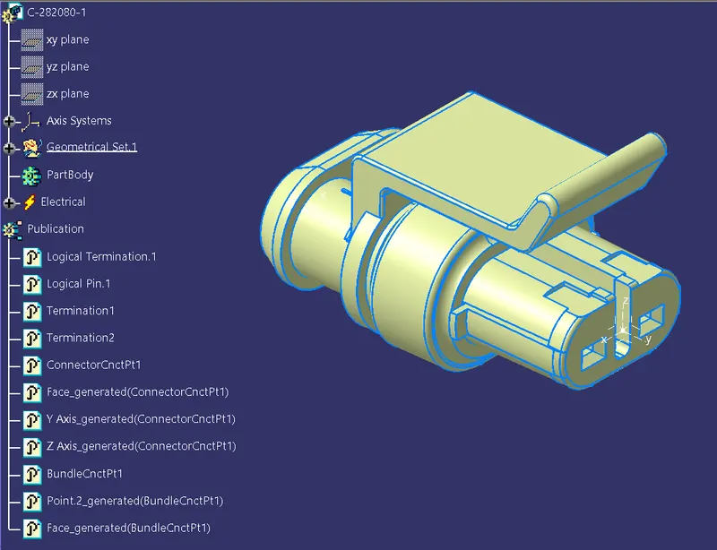
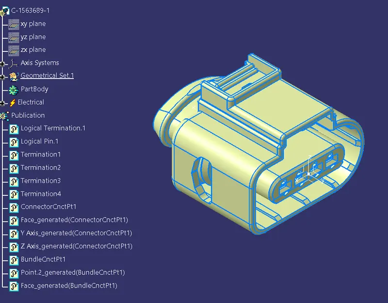
define the connectors electrically by defining all its properties shown in the below images.
Inter Connection Connector
2 Pole Connector:
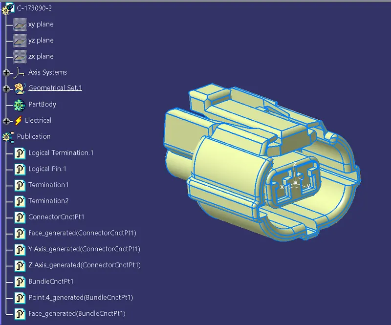
2 Pole Connector:
4 Pole Connector:
Mounting Clip:
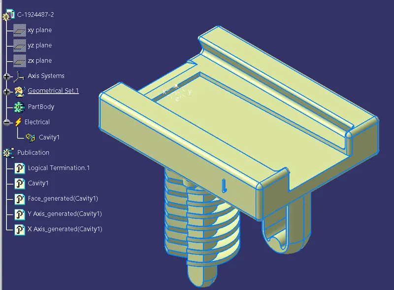
- define the mounting clip electrically by defining all the properties .
- Define the clip as mounting equipment using mounting equipment command. Select cavity command and define the parameters.
Fur Tree clip:
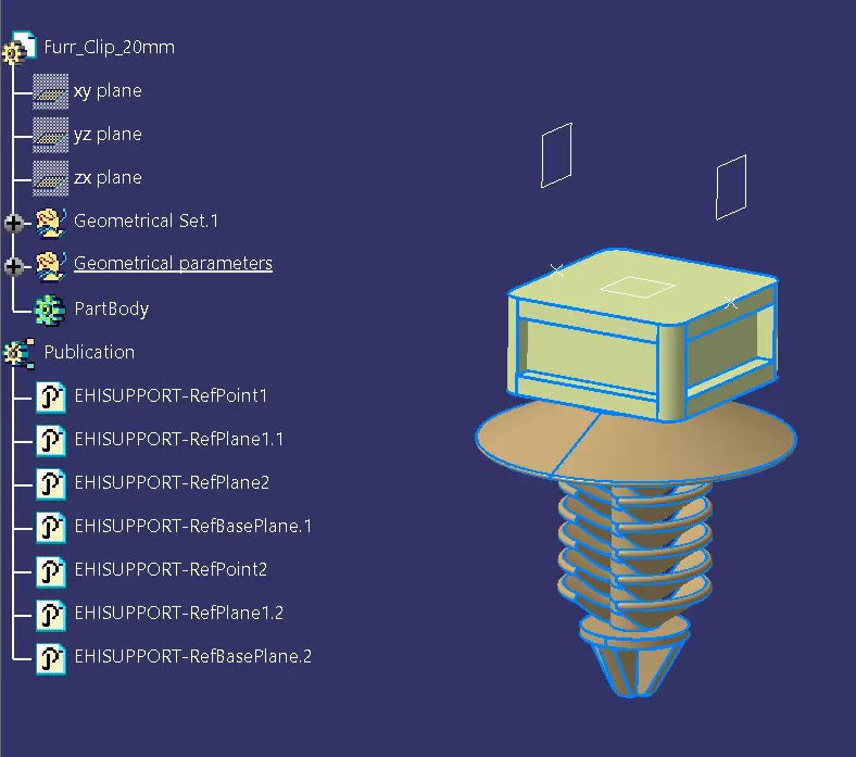
- First define geometrical parameters such as entry point, entry plane, exit point, exit plane and base plane .
- Then switch to electrical part design workbench and define the fur-tree clip as support using support command and define the parameters.
Inter connector connector and mounting clip product file
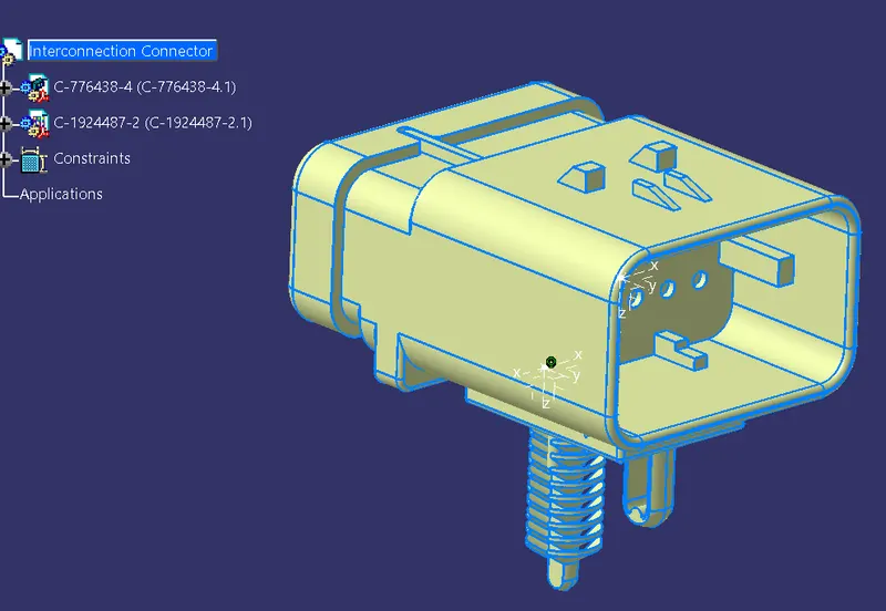
- The above figure shows Interconnection connector and mounting clip with assembled by defining electrical connection.
- This product file uses for interconnection connector placed proper place for harness routing.
P- Clamp:
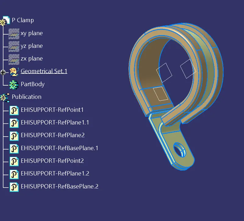
- First define geometrical parameters such as entry point, entry plane, exit point, exit plane and base plane.
- Then switch to electrical part design workbench and define the P-clamps as support using support command and define the parameters
All connectors should define to create the connector connection point,connector connection axis system , bundle connection point .Then Switch to electrical part design workbench and define it as a connector also define connector connection point and bundle connection point.
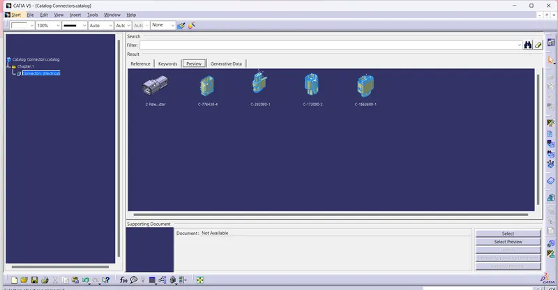
All connectors are added in Connectors Catalaogue:
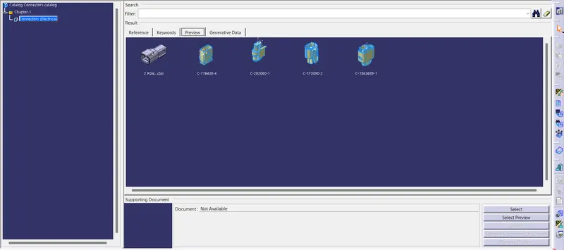
Here we have inter connection connector it require mounting clip for mounting the connector .so cavity connection point should be defined for this connector.
All the connectors defined as electrical connector and defined all the necessary properties to Connectors.Created a catalog document in connector family and stored all the connector data in catalog document.
RHS & LHS Plastic guiding channels:
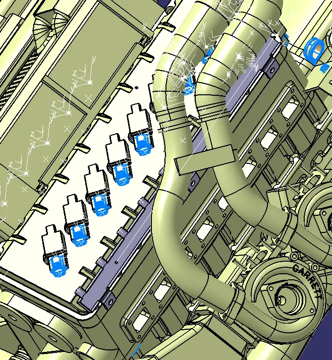
The given V-16 engine has 8 injectors both on the left and right side of the engine which are close to one another, so plastic guiding channel is used for trouble free routing of the wiring harness inaddition it provide thermal protection from high temperature zones of the engine.
First create geometrical parameters such as bundle entry points, and external reference line in the part design workbench to route the wiring harness into the guiding channel trhen define the guiding channel as a electrical part by using the define equipment option .define all the properties to the channel .
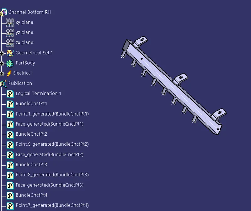
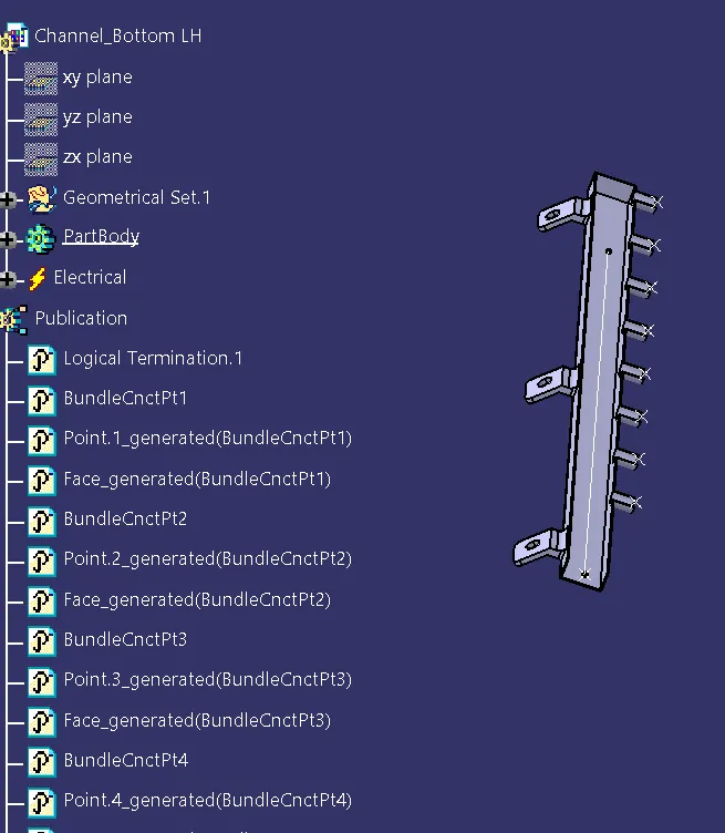
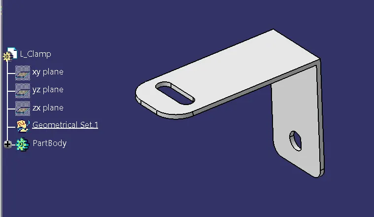
L- Clamp (sheet metal bracket):
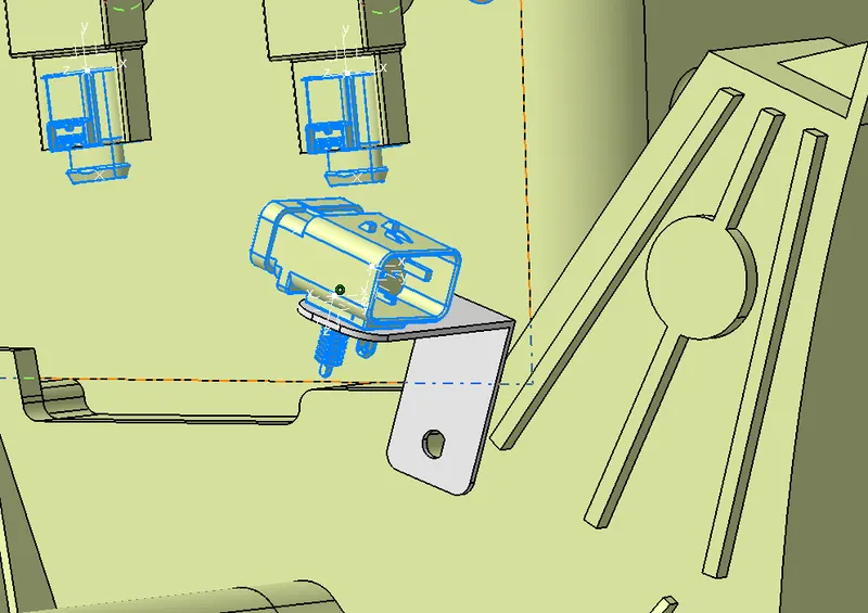
Add sheet metal bracket in order to provide parking for the interconnection connector. Also, we have to make sure that the bracket is placed inside the context assembly and outside of engine and geometrical bundle assembly.
HARNESS ROUTING AND PACKAGING:
The Below Main important packaging rules and best practices to be considered during wire harness routing and placing of the clips and clamps are as follows –
- Distance between two clamps on a straight branch should be minimum of 200mm.
- The minimum branch length should be 50mm.
- Minimum distance between clip and nearest branching point should be 25mm.
- The minimum distance between two straight connection points should be 200mm.
- The minimum distance between two breakout points should be 50mm.
- To limit the number of branches from a single branch point to 4.
- Avoid routing wiring harness near the exhaust manifold and its components and also from other unshielded heat sources. If re routing is not possible then maintain a minimum distance of 200mm.
- Try to avoid use of too many metal brackets on engine. Try to use the available threaded bosses on engine or demand for it.
- Enough clamps shall be provided to ensure positive clearance with surroundings and safety of wiring harness.
- P - Clamps, Fir tree clips and other clips can be added to the Geometric bundle as they are electrically defined and are part of the Wire harness routing and should be provided with the Wire bundle package.
- Enough slack should be provided to the wiring harness which help not to get damaged during the Engine rocking or starting condition.
- The wire harness routing should be done in such a way that it is easy in manufacturing and serviceability.
- The wire routing should be done keeping in mind the cost effectiveness of the bundle package.
- To avoid the harness routing and clipping in blind zones of the operator during the assembly and the service.
- To provide proper slack at end connectors so that there will be no tension on the wire bundle.
- To avoid sharp edges on the sheet metal parts and if it is not possible then provide protection parts to prevent damage of the wire bundle.
- To provide separate branch points for separate connectors to ensure Poka-Yoke.
Keeping all the above packaging rules we can start the routing of the wire and provide clipping and clamping wherever necessary during the routing process.
Creating Harness Context Assembly product File:
Context assembly is nothing but the product file which contains the engine 3D-CAD data and the engine harness geometrical bundle. Here the geometrical bundle product contains all the connectors and other mounting equipments, clips and clamps which are electrically defined for the assembly. Sheet metal L-clamp are added in the main context assembly.
The we need to switch into the electrical harness assembly workbench and Geometrical bundle product file should be electrically defined using the Define Geometrical bundle option before adding any parts into it.
The available connectors are added into the geometrical bundle and properly positioned onto the fuel injectors, camshaft sensors, vehicle speed sensor, neutral position sensor and engine coolant sensor.manipulation tool is used to place the connectors.
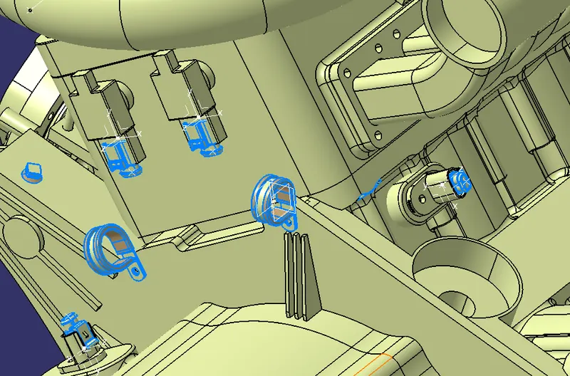
Connectors and clamps are added and placed by required position by using manipulation command
Here we have one interconnection connector to connect engine harness system to vehicle harness system.so it required additional parking provision.Existing bolt on the engine is used to mount the sheet metal bracket. The bracket should be provided with a suitable locking feature in clockwise direction.first mount the clip on the sheet metal bracket .Then the interconnection connector is electrically connected with the mounting clip by using connect electrical devices command in the electrical assembly design workbench.
Adding supporting components like p-clamps and fir-tree clip . P-Clamps are mounted on the existing bolts and screws to provide positive clamping and ensure proper clearance management for the wiring harness routing and also help to prevent the harness fouling from unwanted mechanical components.
P - Clamp and the Fir Tree can be placed at appropriate location and ensure clearance management.
The p – Clamps can be mounted to the existing holes provided on the Engine block in which the screws to tighten the Engine block.
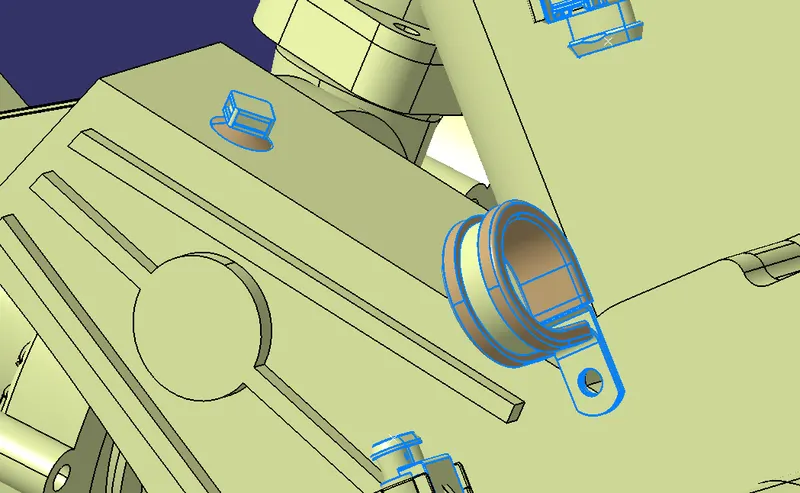
After finalization of the routing, request the Engine design team to provide the threaded holes for fix the Fir tree clips as per their location.
Add guiding channel for routing the wiring harness to the fuel injectors.it deals with clearance management and thermal protection of the wiring harness in the high temperature zones.Then request engine design team to provide additional threaded holes required to mount the guiding channels in proper location by using bolts or screws .
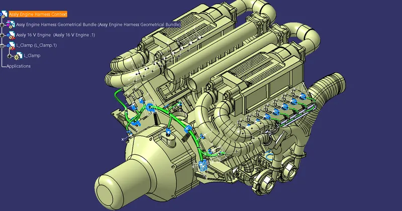
After define the geometrical bundlel electrically, Then select the multibranchable command to start the bundle routing and click on the route definition.
The bundle routing starts from interconnection connector and then to the P-clamps and to the guiding channels. Adding branche points to route the wiring harness from main branch to various connectors.
To route the wiring harness through the guiding channels select external curve option and click on the line created in the guiding channel.then add branch points to route the wiring herness from the guiding channel to the connectors .proper bend radius and slack provided for the bundle segment to avoid stress on the wire.
Adding Protective Coverings:
Add protective coverings on the wiring harness to protect wiring from high temperature . protective covering created by using define protection part command in the electrical part design workbench. Select part , and define the parameters as per the requirement.
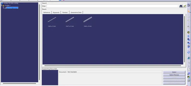
The created corrugated tube can be added into the catalog by store device command and selecting the catalog file created for protective covering. then appropriate protective covering added to the bundle segments.
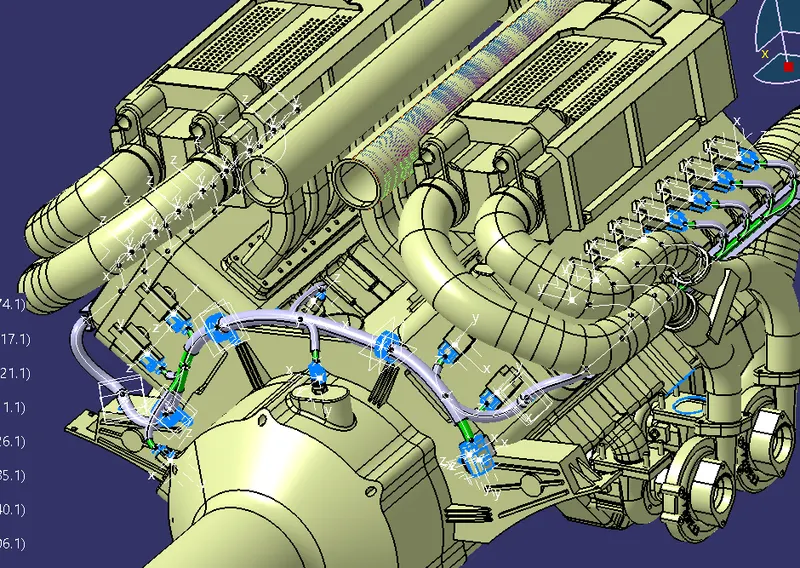
Selection of corrugated tubes are mainly driven by the wiring harness bundle diameter and temperature resistance requirements.
Black color tubes are widely used in automotive and off-road applications but other colors are also used to highlight the critical harnesses for example Emission system harnesses.
Protective coverings Catalogue
Checking The Harness Bundle segment cointinuity:
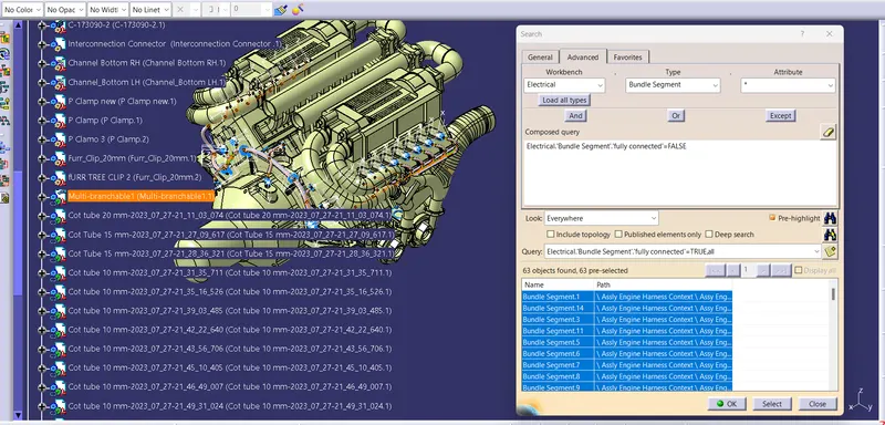
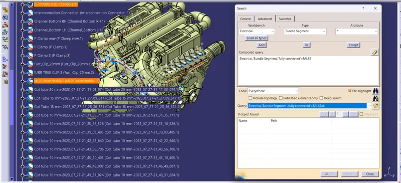
We need to ensure that the entire bundle is fully connected.
Go to edit and then click on search command.
Go to advanced
Select workbench as electrical, type as bundle segment and attribute as Fully connected
The select result should be as TRUE or FALSE and the click search to see the connectivity analysis result
After result,
Selecting the "TRUE" option will show all the connected bundle segments while the selecting "FALSE" will show all the non-connected bundle segments.
For now, we will select "TRUE" and search for results. All the bundle segments are highlighted and found showing that all the bundle segments are electrically connected.
WIRING HARNESS FLATTENING:
Wiring harness Bundle packaging process is done. Now we need to convert the geometrical bundle into a flattened wiring harness in the Electrical Harness Flattening Workbench.
To create the Flattened Harness, we need to create a new product file and switch into the electrical harness flattening workbench.
Now we need to define the Harness Flattening Parameters and then Extract the geometric bundle from the wiring harness context product file.
Then select all the branches and flatten the entire Geometric bundle.
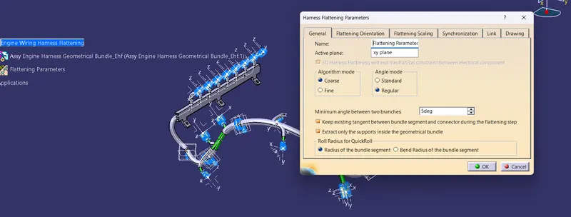
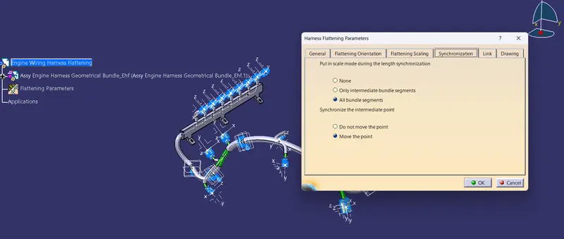
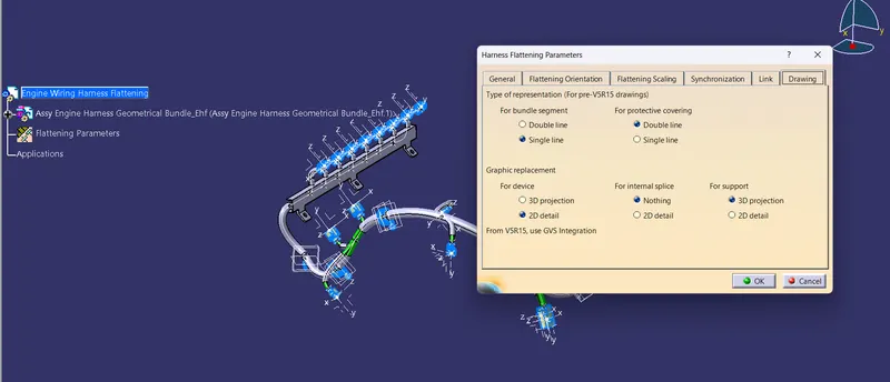
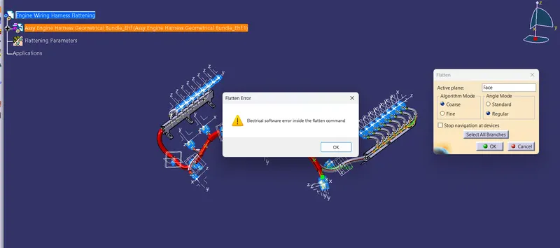
while flattening the engine harness it pop-up a software error .it is due to some software issue so i can submit like these given instrction from support Engineer.
Drawing of the Without flattened wiring harness:
open a new drawing file and Select front view command, then go to the flattened harness window and select a suitable face to create drafting of the harness.
to make the bundle segments visible right click on the drawing sheet and go to properties, in the view tab, highlight '3D wireframe' and 'is always visible' in the dress up settings.
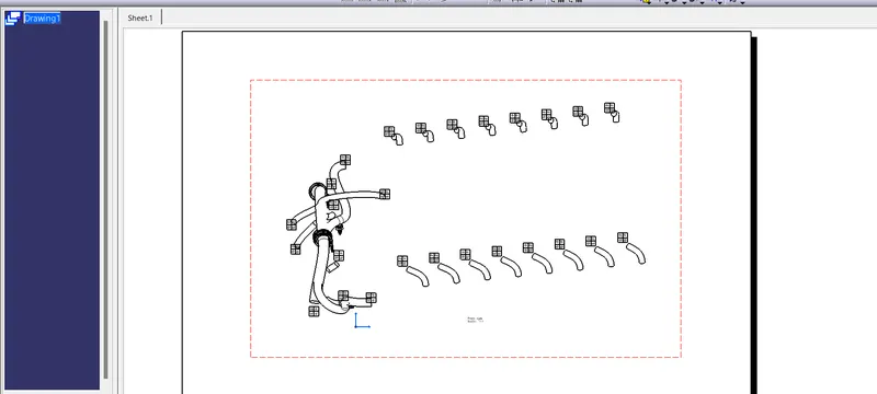
Due to the Harness flattening not happen software error i can submit like these 3D design.
Conclusion
In this project i have successfully routed the wiring harness for the V16 Engine assembly and the flatten-view drawing was not prepared properly due to software error in CATIA V5. Various packaging rules and constraints were considered while routing the harness. After finalizing the wire routing, we can request the corresponding Engine design team to provide additional holes for the mounting of Fir tree clips.