Project 1
Wiring Harness,
In the automotive industry, a wiring harness refers to a standardized assembly of electrical wires, cables, and connectors that are used to transmit electrical power and signals between various components in a vehicle. It acts as a central nervous system, providing a secure and organized way to connect electrical and electronic components within the vehicle.
The wiring harness is crucial in modern vehicles, as it simplifies the electrical system's installation and maintenance processes. Instead of having individual wires running all over the vehicle, a wiring harness bundles and protects these wires into a single assembly. This makes it easier to manufacture, install, and repair vehicles in an efficient and cost-effective manner.
Components connected by a wiring harness may include:
- Engine components: Such as sensors, injectors, ignition coils, and the engine control module (ECM).
- Lighting systems: Including headlights, taillights, fog lights, and turn signals.
- Dashboard and instrument cluster: To connect various gauges, indicators, and buttons.
- Audio and entertainment systems: For speakers, radios, amplifiers, and navigation units.
- Transmission and drivetrain components: For sensors and control units related to automatic transmissions.
- Power windows and locks: Connecting switches and motors.
Wiring harnesses are typically designed and manufactured according to the specific requirements of a vehicle model or a range of models. This means that different vehicles will have different harnesses depending on their features and functions. The harnesses are made from various materials, including insulated wires, connectors, tapes, and protective sleeves, ensuring that the electrical connections are safe, reliable, and well organized.
V16-Engine Wiring Harness
As per the challenge requirements i have designed the wiring harness,
Given engine surface,
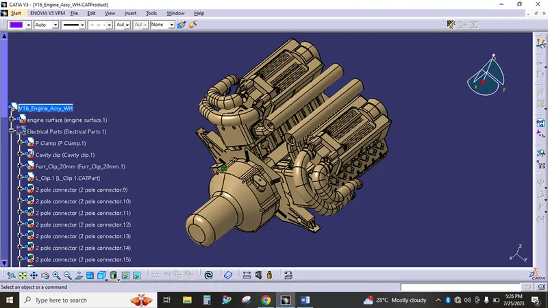
The required connectors can be downloaded in the www.te.com and the challenge given data.
Placing - connectors
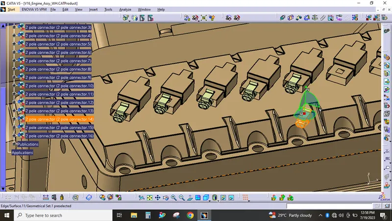
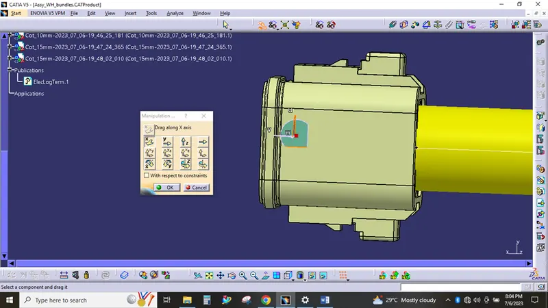
For placing - manipulation and smart move, compass used,
WH bundle creation using multi-branchable command,
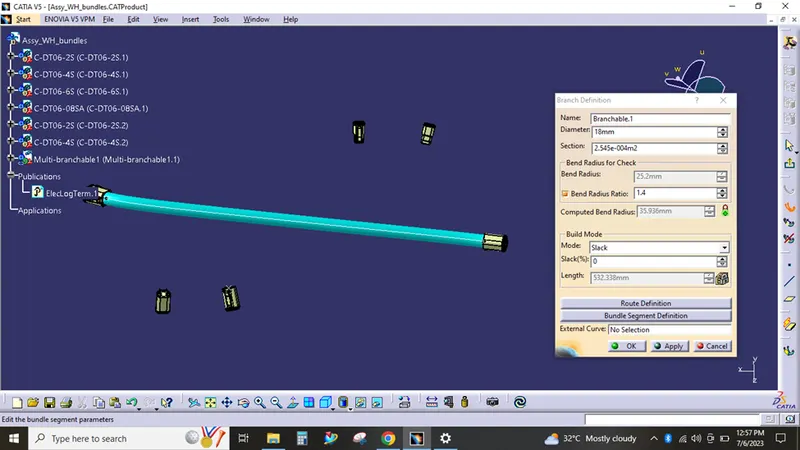
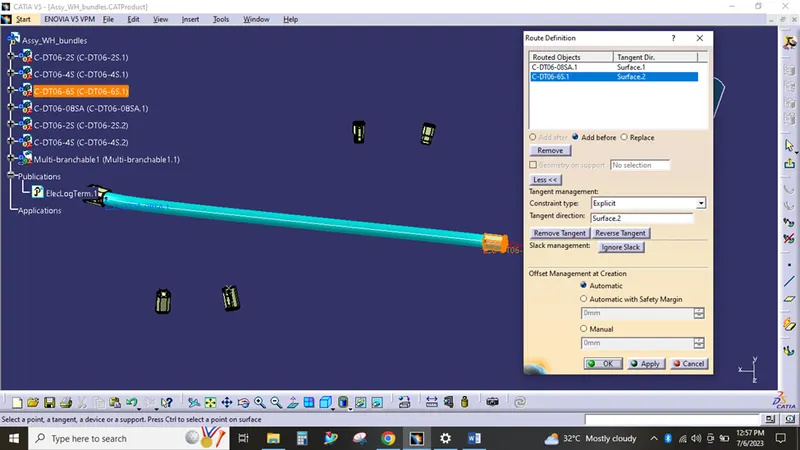
Route definition,
Protection covering,
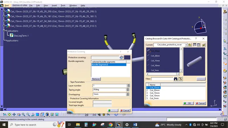
As per the assumed diameter of bundle, the desired protective cover (COT TUBES) has provided from the catalogue,
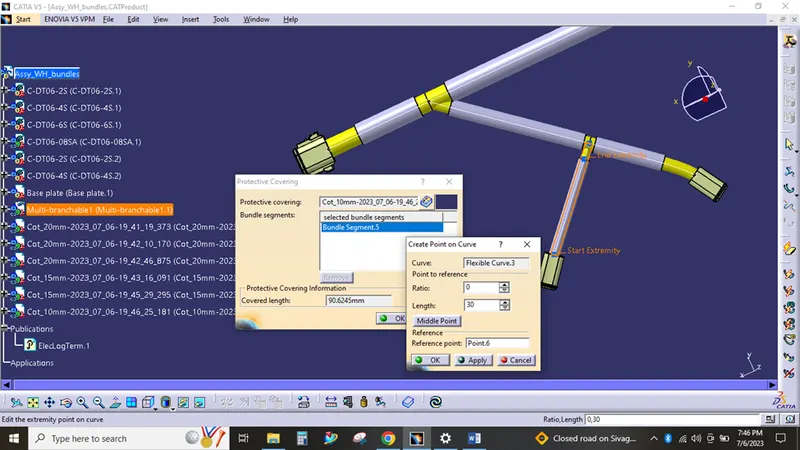
From connector point - 30 mm gap provided for covering
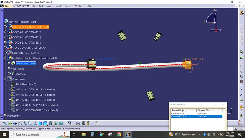
Bundle error snaps,
The most of the bundle error has cleared by "reverse tangent" option.
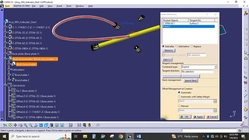
Most of the places in the engine i have used 2 pole connectors,
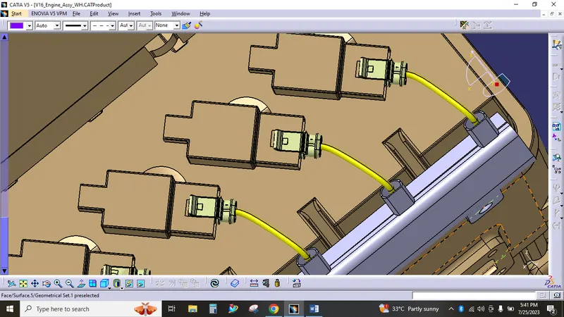
The above image routing can be done by the use of the channel. After the proper placement of the bottom channel the routing has started. Here i have used the external curve option for the channel routing.
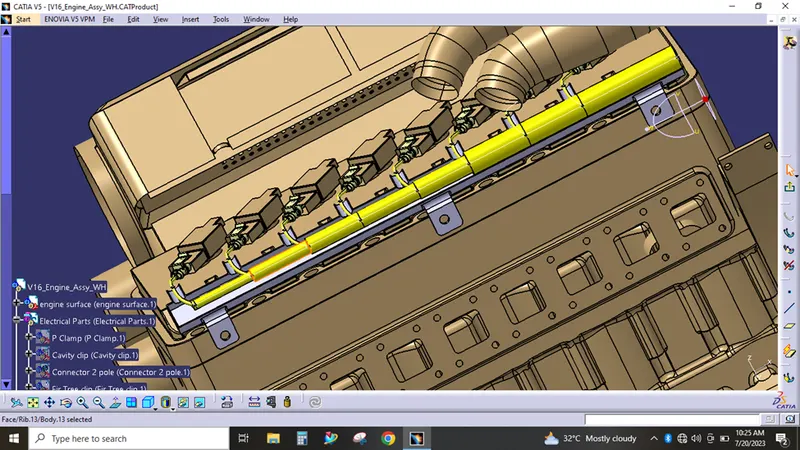
After that the 2 pole connectors routed with the channel wiring, the wire fouling can be avoided here by providing enough amount of slack percentages ( 2% to 5% ) and also changing the branching point positions. The same procedure has followed and the opposite side of routing has done.
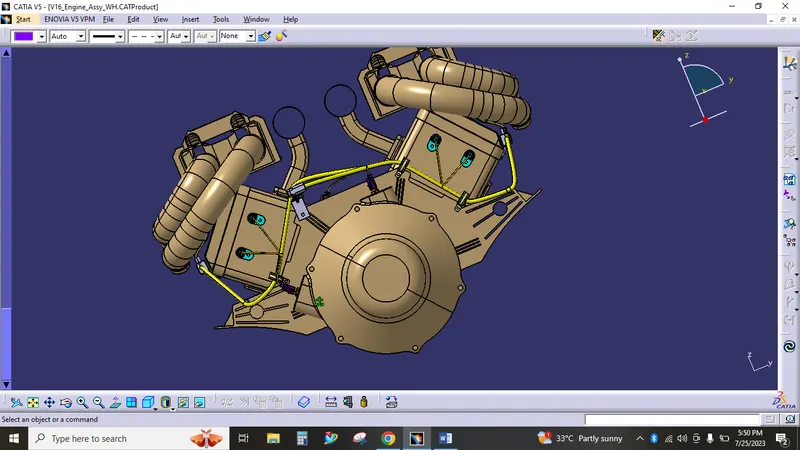
In this lite skin data, there is no points provided for the placing for connectors. So i have taken the available holes for connector placements as per the help video. Based on this i have placed connectors and the connectors are electrically connected by using connect electrical device command.
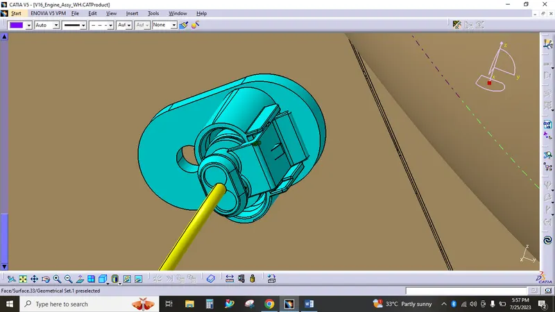
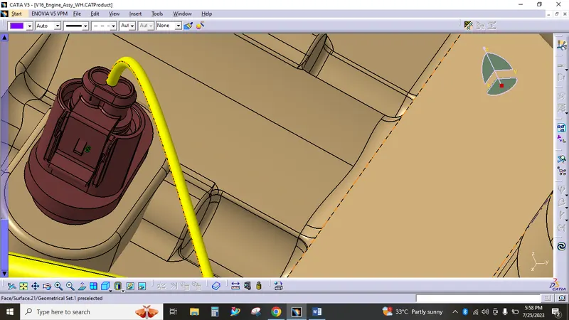
Supports,
Furr tree clip, L type mounting, P clamps has used as support for proper routing. Thses are electrically defined as support and equipment, While defining proper points and planes were created and defined.
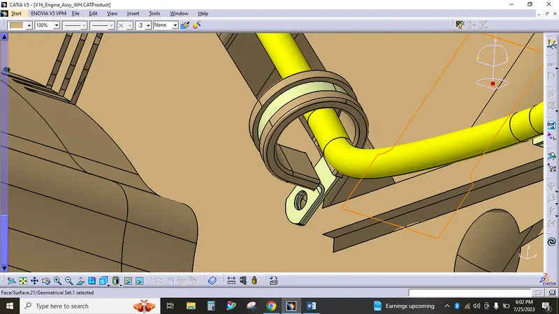
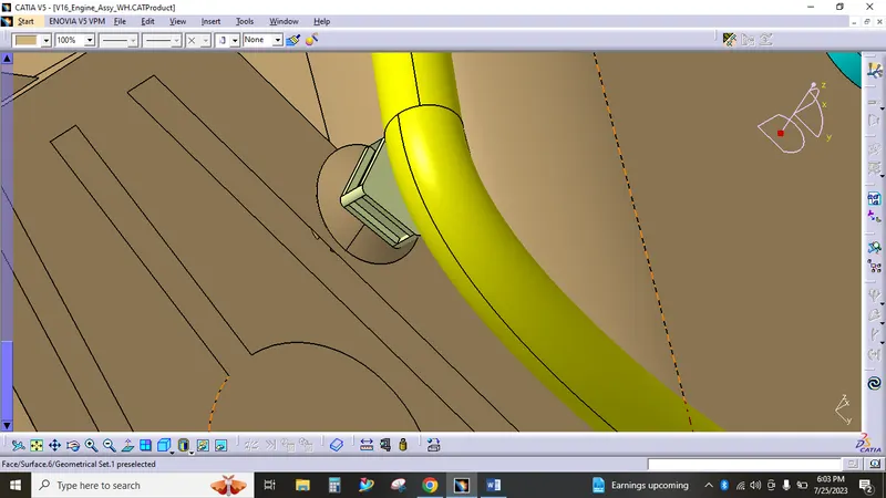
L clip used as a support above that furr clip and a cavity clip has used to fix the inter connection connector and for routing.
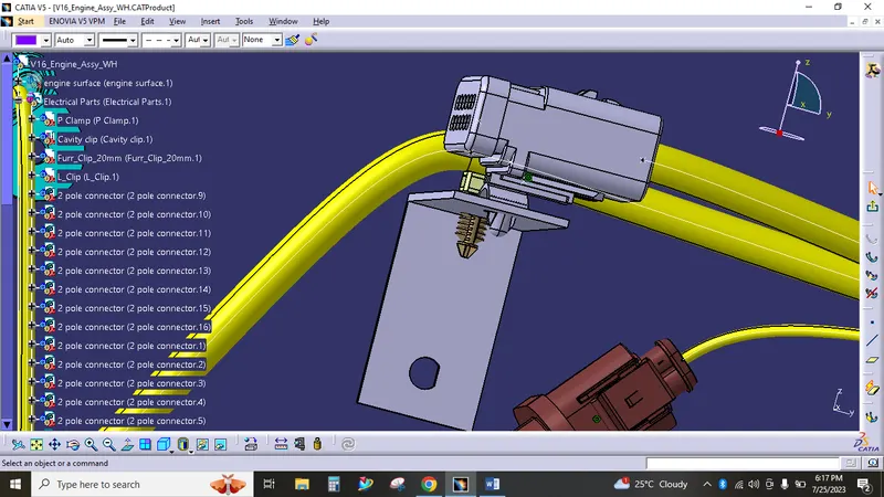
Connection checking,
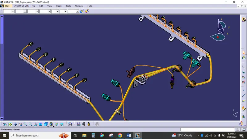
I have maintainted one branch to another branch distance as more or equal to 50mm.
From one branching point only 3 to 4 branches only connected.
Final wiring harness,
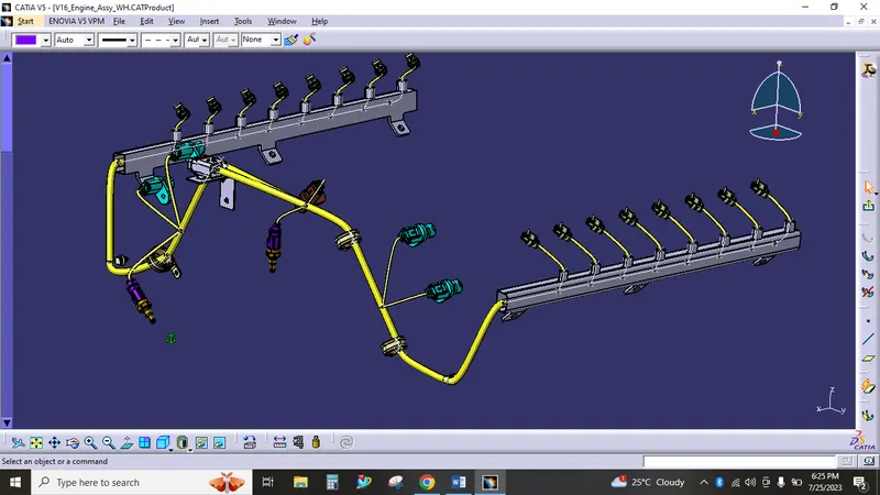
I have maintained the main trunk dia. as 10mm and the branched dia. as 4mm to 6mm. One 12 pole inter connection connector used to start the routing, we can operate the total engine harness on/off by this connector connection.
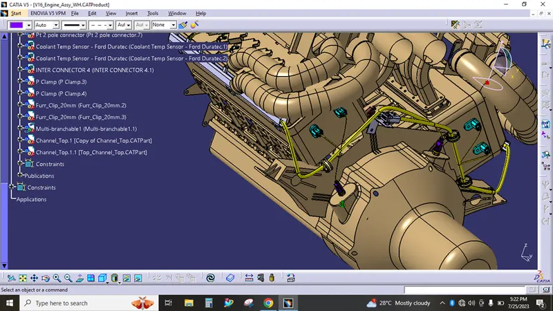
Final assembly,
Harness Flattening,
After the complete connection check the flattening made,
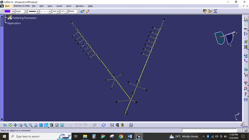
Drawing,
Scaling 1:2
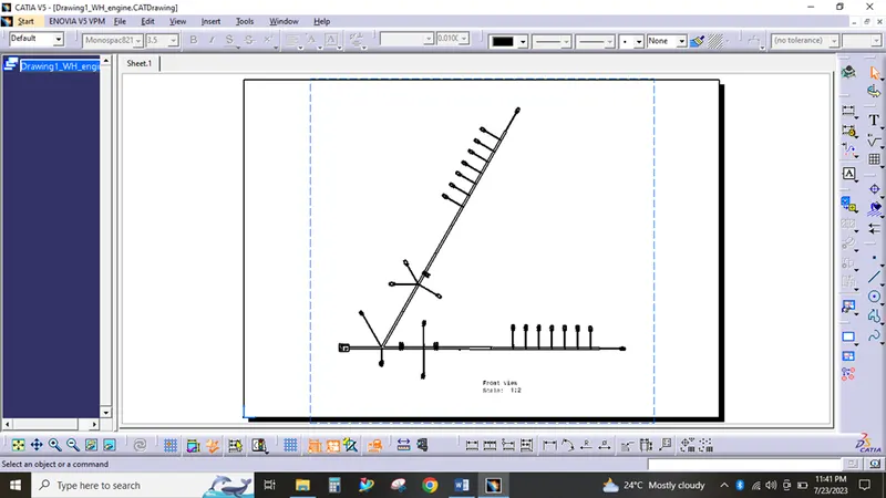
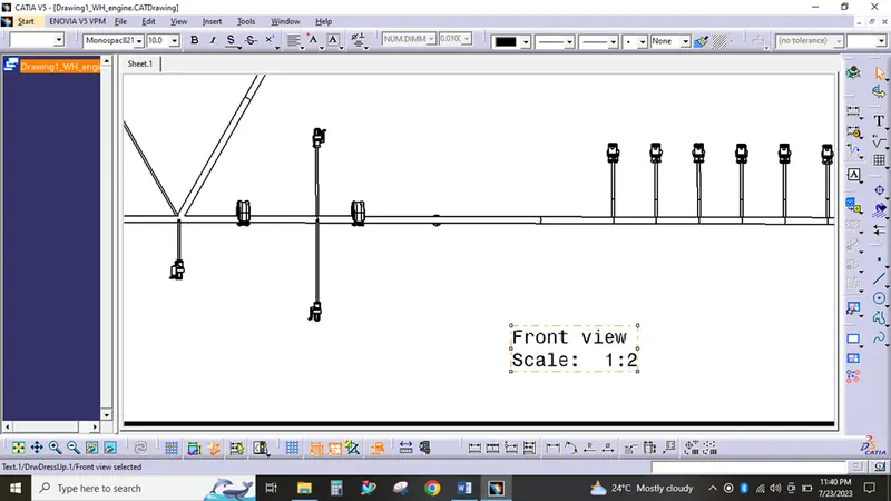
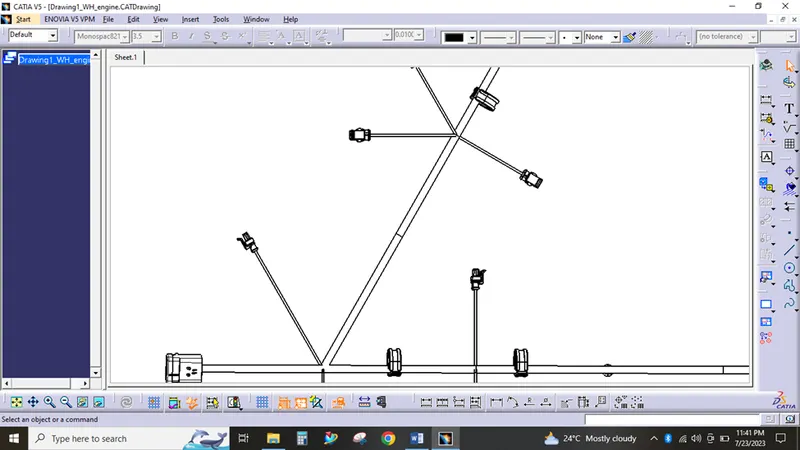
Thus the engine WH has routed with real time considerations. And i have attached the assembly files, part files, and multibranchable files, catalogues as a single zip file.