Project 1
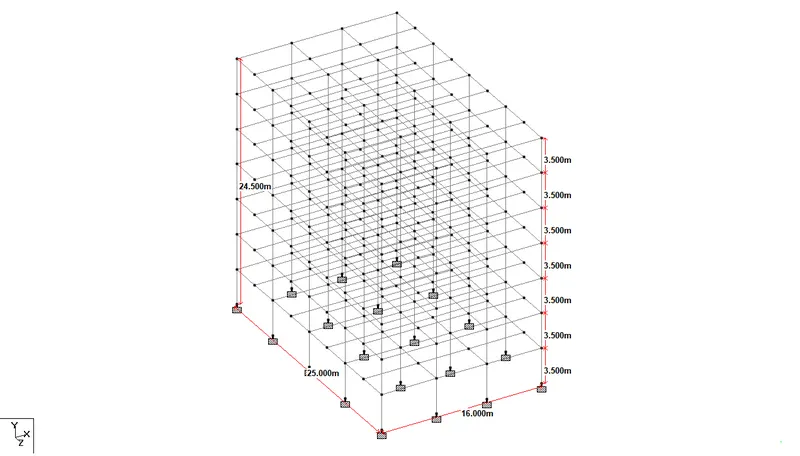
1. Design a multi-story Residential Building located in Bangalore using STAAD Pro Connect Edition. The specification must be as follows:
|
Building floors |
G + 6 + R |
|
Plan dimension |
B = 25m , L = 16m |
|
Storey Height |
h = 3.5m |
|
Soil |
Hard soil |
|
Use |
Residential Purpose |
|
Safe Bearing Capacity |
180 kN/m2 |
|
Maximum slab thickness |
150mm |
- Assume -suitable sections for structural elements. Follow IS456, IS1893, and IS 875
- Aim:
To design a multi-story Residential Building located in Bangalore using STAAD Pro Connect Edition.
- Procedure:
Unit weight of the materials
Reinforced Cement Concrete = 25k
Plain Cement Concrete = 24k
Cement Concrete Screed = 20k
Cement Masonry Units = 22k
Structural Steel = 78.5k
Soil = 18k
Dead Load
Floor slab
Slab weight = 3.75k
Partitions = 1.5k
Floor Finish = 2.5k
Miscellaneous = 1k
Total Floor Load = 8.75 k
Roof slab
Slab weight = 3.75k
Insulaions and Water Proofing = 0.5k
MEP Services = 0.5k
Miscellaneous = 0.5k
Total Roof Load = 5.25k
Live Load
Floor slab
Common Corridor = 3k
Total Floor Load = 3k
Roof slab
Accessible Roof = 1.5k
Total Roof Load = 1.5k
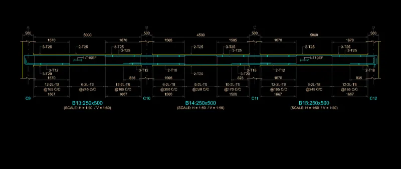
- Design of Slab
Span Shorter Direction (Clear) ly = 3.125.00 m
Span Longer Direction (Clear) lx = 5.500 m
Live Load on the Slab LL= 3.00 kN / m2
Compressive stength of concrete fck = 40 N / mm2
Yield strength of steel fy = 415 N / mm2
Unit weight of concrete Ƴ = 25.00 kN / m3
Unit weight of floor finish 100 mm Ƴ= 22.00 kN / m3
Clear concrete cover =25.00 mm
Bearing of slab B=250.00mm
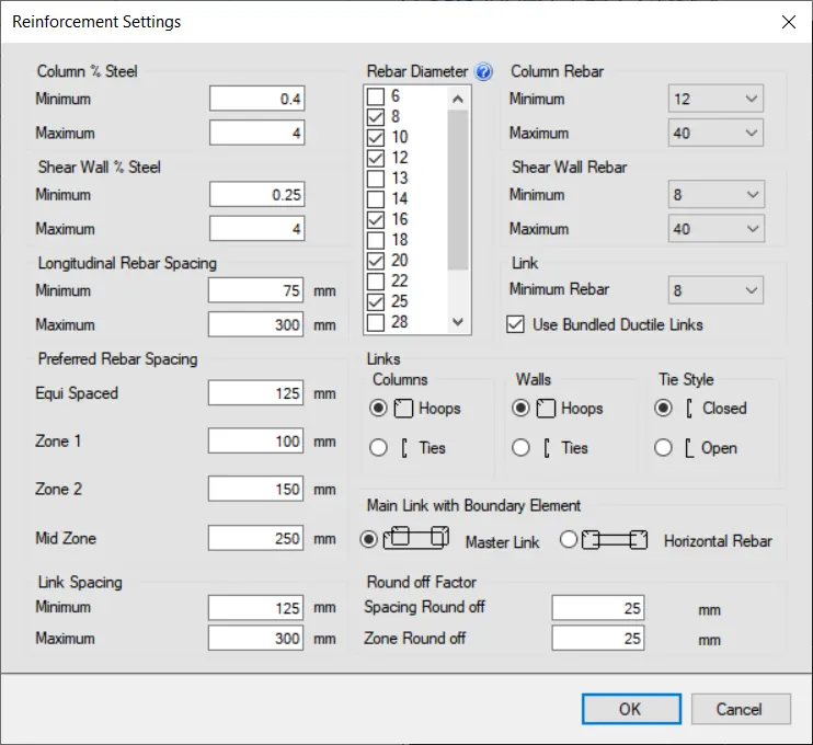
- Step 1
Cl 24.1
Span to effective depth ratio l/d = 32
Minimum effective depth d = 97.66 mm
Overall depth D = 127.66 mm
Provide Overall depth D = 150.00 mm
Dia of bars for short direction Φ=10mm
Dia of bars for long direction Φ = 10 mm
Effective Depth d=120.00mm
Loading on the slab
Dead Load of the slab (DL) 3.75.00kN / m2
Super Dead Load = 5.00 kN / m2
Live Load on the slab=3.00 kN / m2
Total Load on the slab (TL) =12.00kN / m2
Design Load = (Total Load x Load Factor i.e. 1.5) ie 18.00 kN / m2
Effective Span lx = 5.17 m
ly=5.17 m
Ratio ly/lx= 1.000 Two Way
T26/27
1.0 ax 1.10 ay
For negative moments (at top) 0.047 0.047 0.053 0.047
For positive moments (at bottom) 0.035 0.035 0.045 0.035
- Step 2
BM per unit width of slab Mx = ax w lx2 My = ay w lx2
For negative moments (at top) 22.60 22.60KN-m/m
For positive moments (at bottom) 16.83 16.83nKN-m/m
Shear force , V 0.5wlx 46.52kN/m
- Step 3
To check the effective depth of slab
Mu,lim = 0.138fckbd2
d=63.99 mm
- Step 4
Depth of slab for shear force
T20 τc,max =4N/mm2
τc=0.3
Cl 40.2.1 k=1.2D=200mm
τc=0.36 N/mm2
τv=Vu / bd
=0.28N/mm2
0.28 0.36 4
SAFE
Step 5
Determination of areas of steel
Mu = 0.87fyAstd(1-Astfy/fckbd)
For Negative moments Mu Top = 22.60
Ast = 463.99 mm2/m
For Positive moments Mu Bot = 16.83
Ast = 345.52 mm2/m
- Step 5.1
Determination of distribution steel
Astmin =0.12bd
202.8mm2
- Step 5.2
Selection of reinforcing bars
Area of bars (Top steel) =113.04mm2
Spacing =244
=240mm
Provide 12mm bars at a spacing 240mm
Area of bars (Bottom steel=113.04mm2
Spacing =327
=300mm
Provide 12mm bars at a spacing 300mm
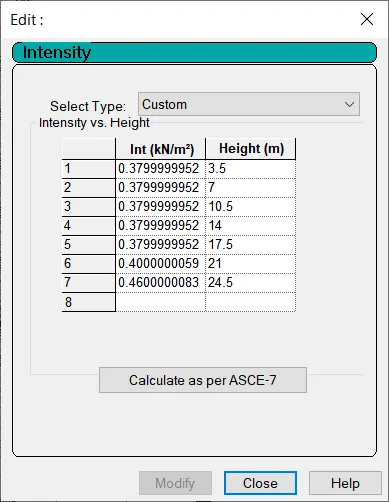
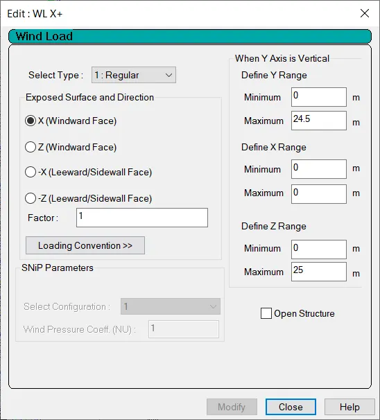
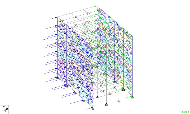
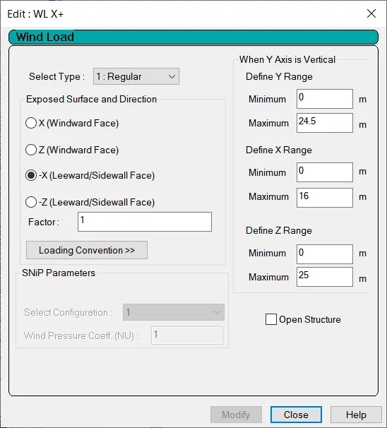
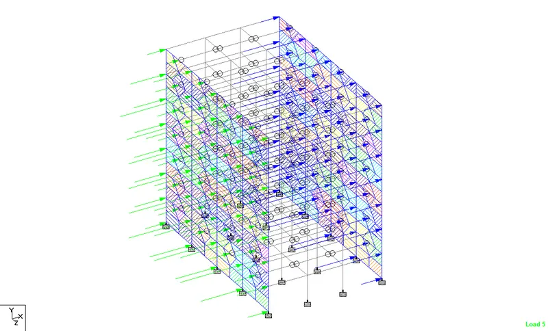
- Calculation of wind load
Design Wind Speed Vz =Vb k1 k2 k3 k4 m/s
Basic Wind Speed (Banglore) Vb =33 m/s
Probability factor k1 = 1
Terrain factor , Category for k2 =Category 4 B
Topography factor k3= 1
Design Wind Pressure Pz=0.6 Vz2
Height k2 Vz Pz Pz in kN
3.5 0.76 25 377.40 0.96
7.0 0.76 25 377.40 0.96
10.5 0.76 25 377.40 0.96
14.0 0.76 25 377.40 0.96
17.5 0.76 25 377.40 0.38
21.0 0.78 26 397.93 0.43
24.5 0.84 28 461.04 0.46
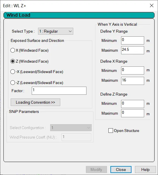
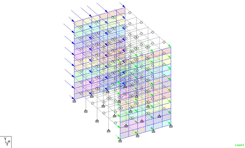
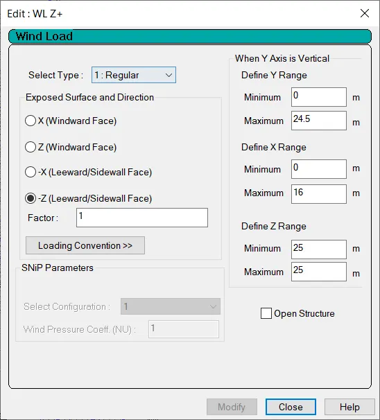
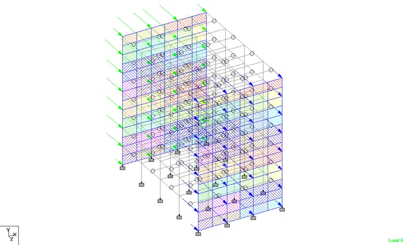
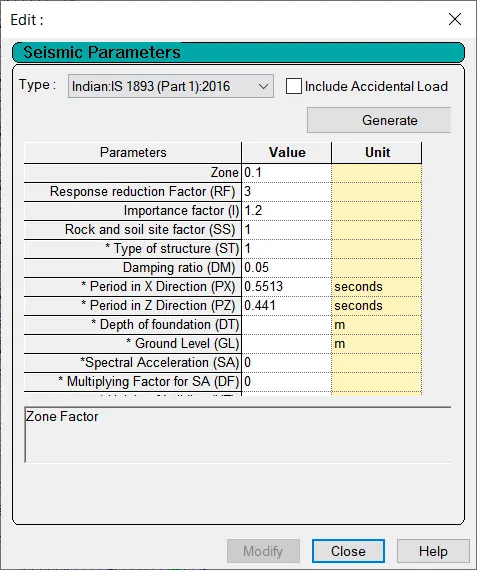
Calculation of seismic load:
Design Base Shear VB = Ah W kN
Design Horizontal Acceleration Coefficient Ah = {(Z/2) x (Sa/g)}/(R/I)
Zone factor Z = 0.1 (Banglore)
Soil Condition factor , Sa / g
T=0.09h/
Height of building h=24.5m
Base dimension of building Along X = 16
Along Z = 25
T along X =0.5513s
T along Z =0.4410s
Sa / g =1.814 Along X
Sa / g =2.268 Along Z
Response Reduction Factor R = 3
Importance Factor I= 1.2
Horizontal Acceleration Coefficient Ah = 0.0363 Along X
Ah =3.68%
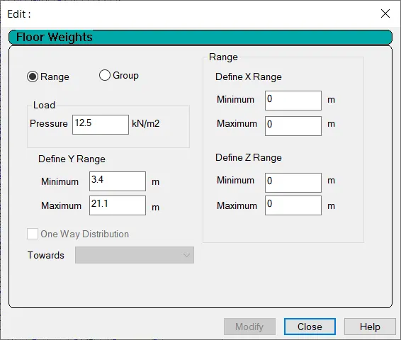
- Seismic Weight
Area of Each floor A = 400m^2
Due to Dead Loads , Typical Floor DL = 12kN/m^2
W DL = 5000kN
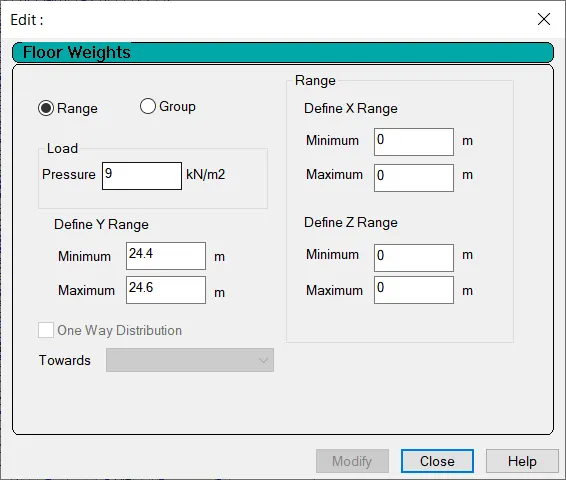
Due to Dead Loads ,Roof DL roof =9kN/m^2
=3600kN
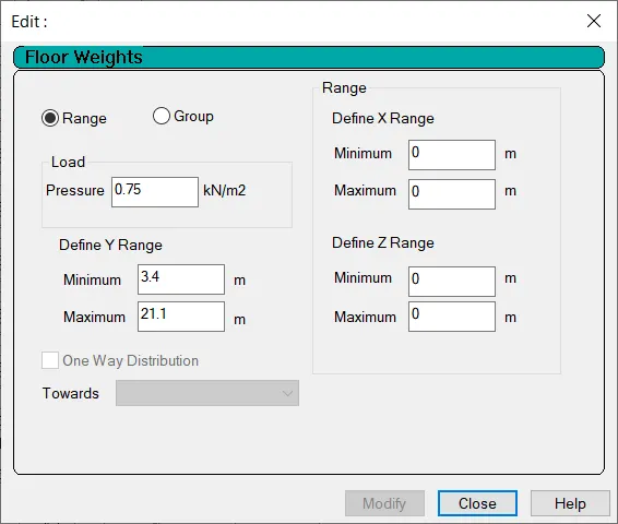
Due to Live Loads , Typical Floor LL = 3kN/m^2
W LL = 300kN
Due to Live Loads , Roof LL = 1.5kN/m^2
W LL =0
Total Seismic Weight W = 35400kN
Design Base Shear VB = 1284.35kN
Horizontal acceleration cofficient Ah= 0.0454 Along Z
=4.54%
- Seismic Weight
Area of Each floor A = 400m^2
Due to Dead Loads , Typical Floor DL = 12.5 kN/m^2
W DL = 5000kN
Due to Dead Loads ,Roof DL roof =9kN/m^2
=3600kN
Due to Live Loads , Typical Floor LL = 3kN/m^2
W LL = 300kN
Due to Live Loads , Roof LL = 1.5kN/m^2
W LL =0
Total Seismic Weight W = 35400kN
Design Base Shear VB = 1605.35kN

- Result & Conclusion
Thus the multi-story Residential Building located in Bangalore has been designed for the given input.
1- Design basis report-
The Basis of Design document includes information on the project and explains the systems, client expectations, and why the systems were selected and designed. The Design Criteria usually only include a list of expected design information in tables that should be met.
- Sections of a design report
- set the problem in context.
- summarise what you have done.
- describe your design solution.
- report on its performance.
- provide key recommendations.
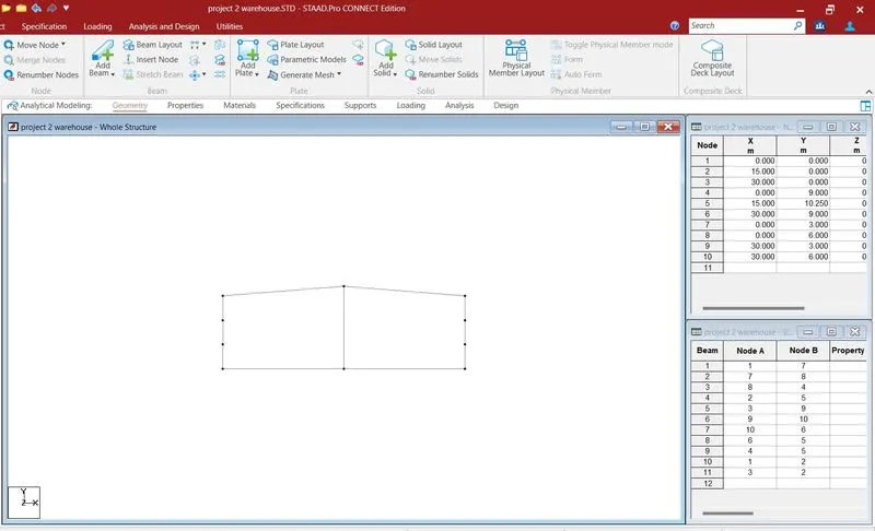
1] Roof Slope Calculation:
Roof Slope = 1 in 12
Width, b = 30 m
X / (b/2) = 1/12
X = (30/2) / 12 = 15/12
X = 1.25 m
Total height =9 +1.25 =10.25
2] Modeling in staad pro:
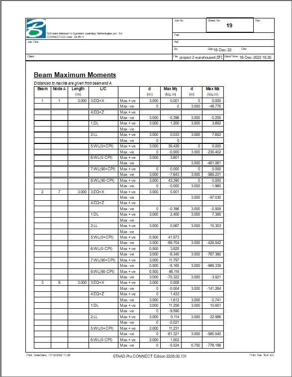
Create structural model using STAAD Pro Connect Edition:
Step 1: Model Creation:
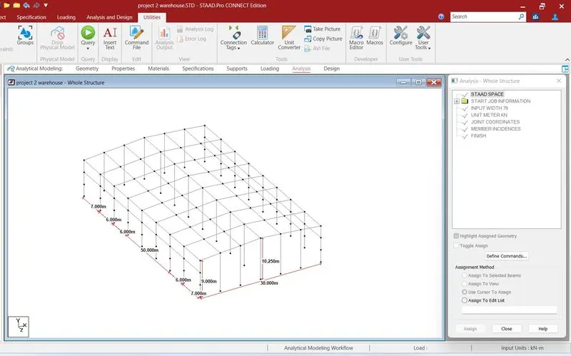
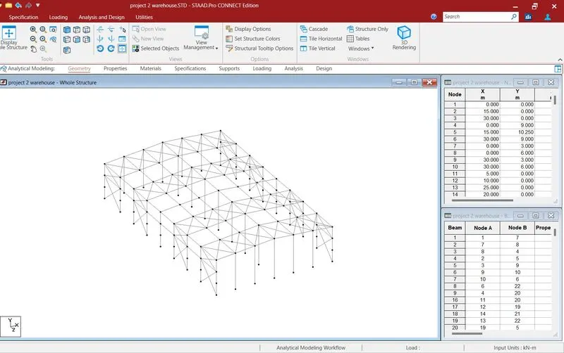
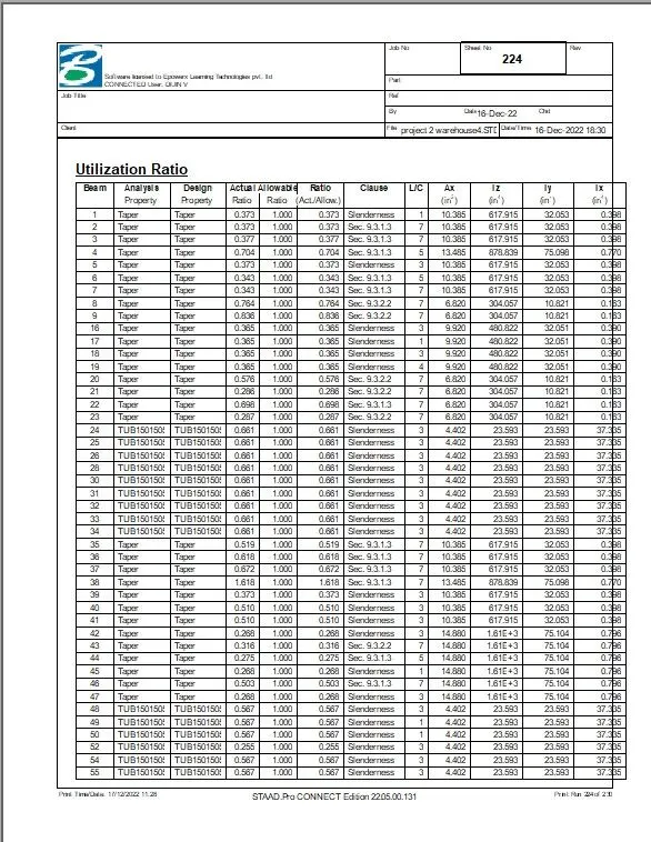
Step 2: Assign Properties:
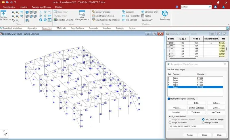
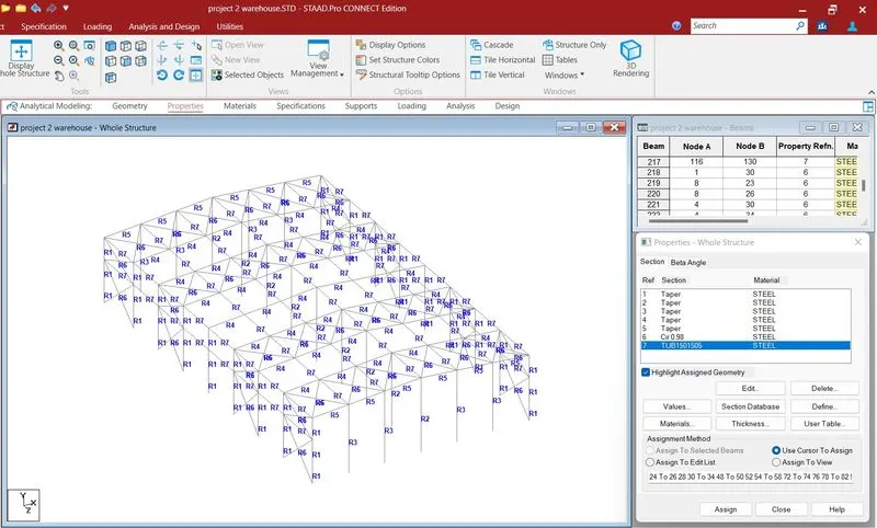
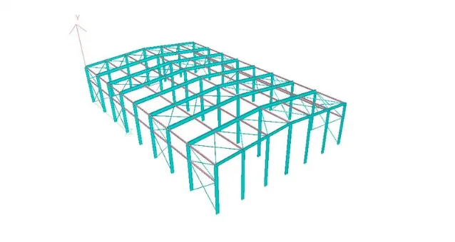
3D View:
Material : Steel
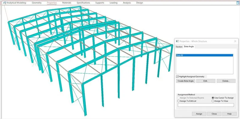
BETA Angle 90 degree for wind / gable columns
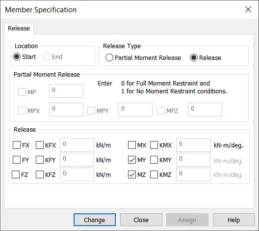
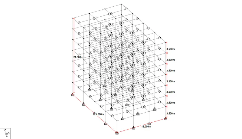
Step 3: Specification:
- Member Tension
- End MY MZ
- Start MY MZ
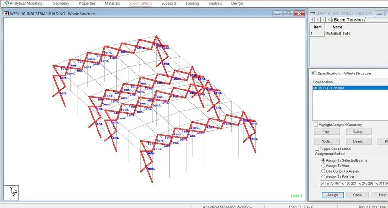
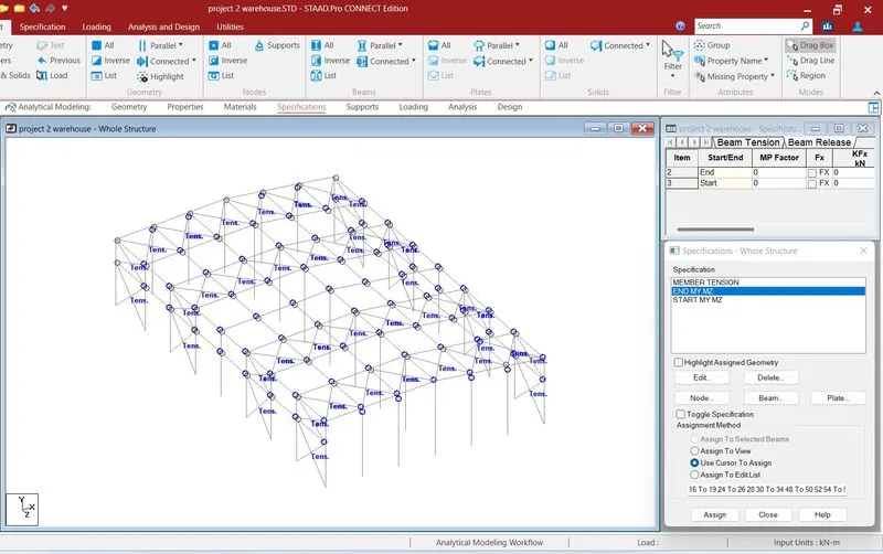
Step 4: Support:
- Pinned
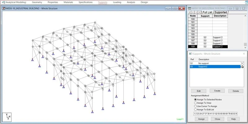
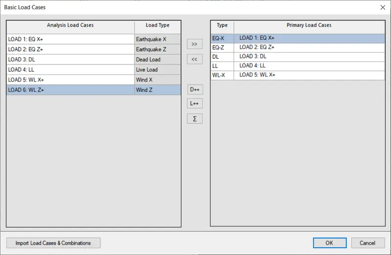
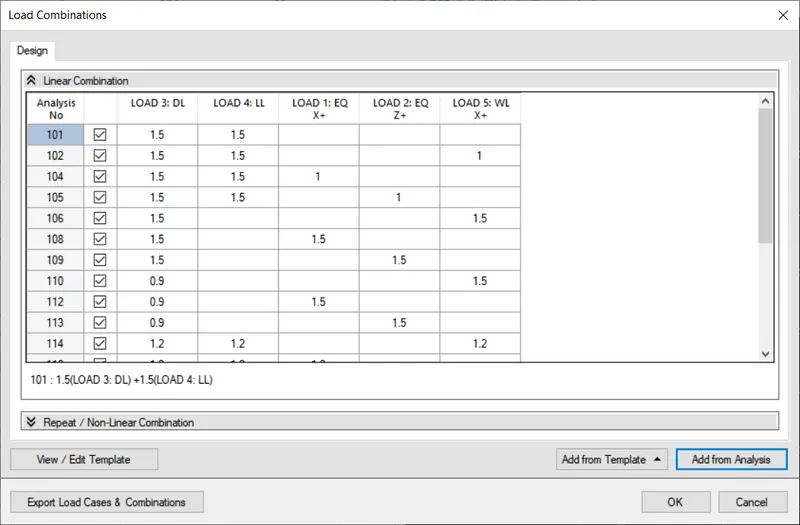
Step 5: Load Case Definition:
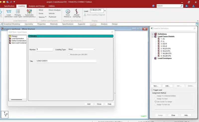
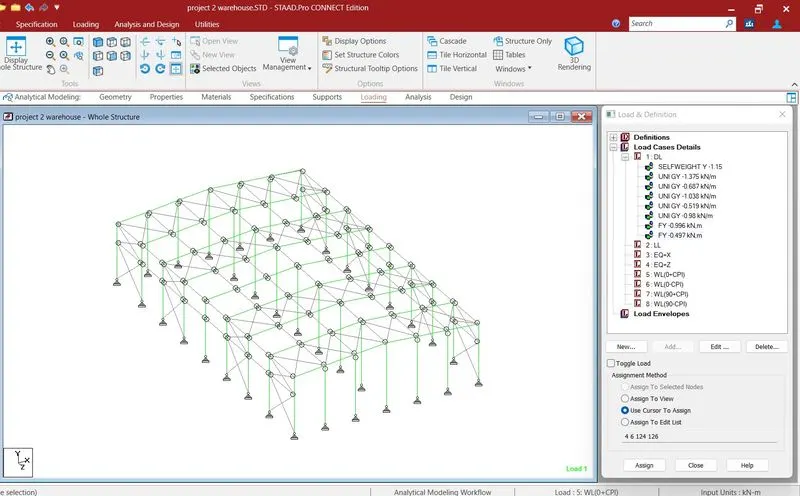
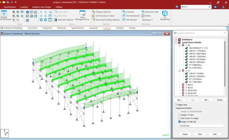
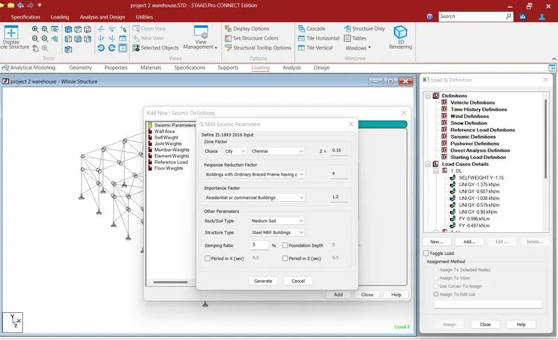
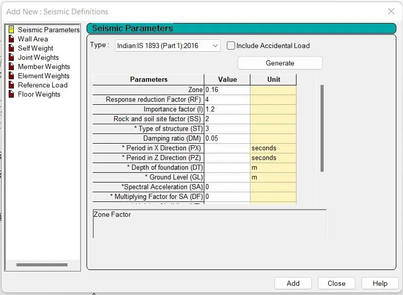
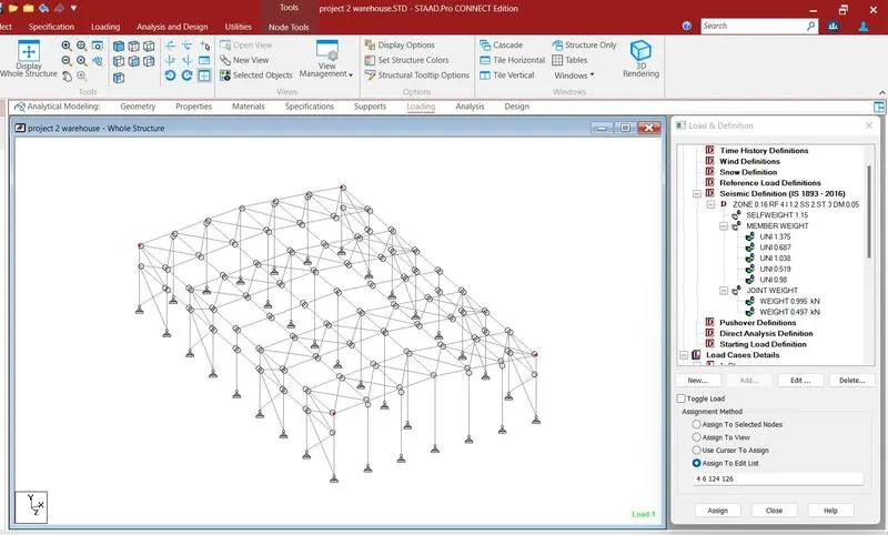
- Seismic Definition:
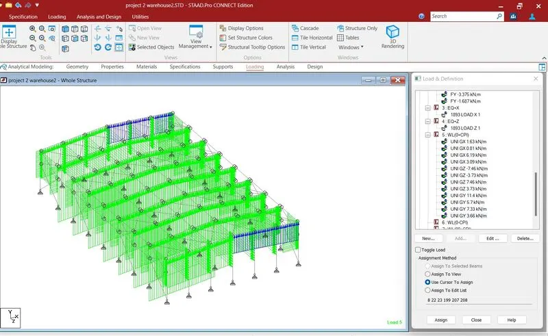
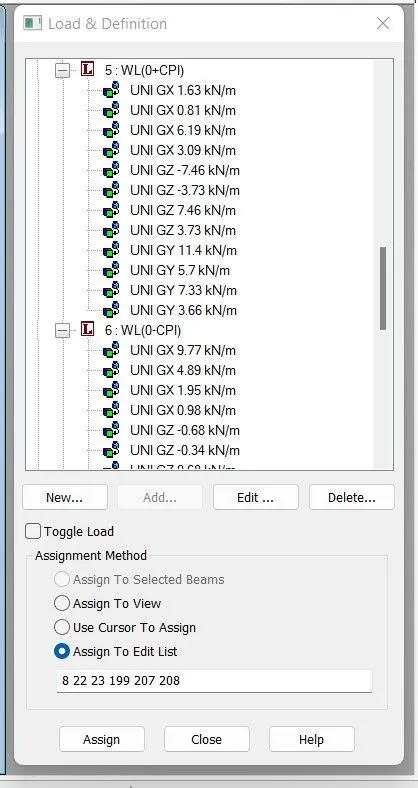
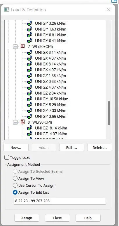
- Wind Load Definition:
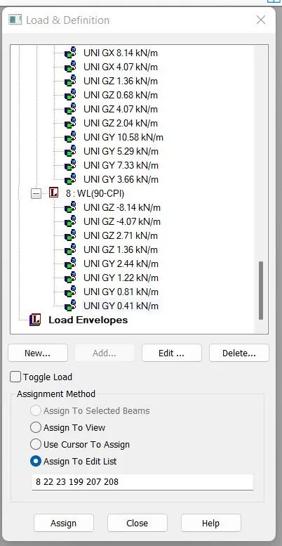
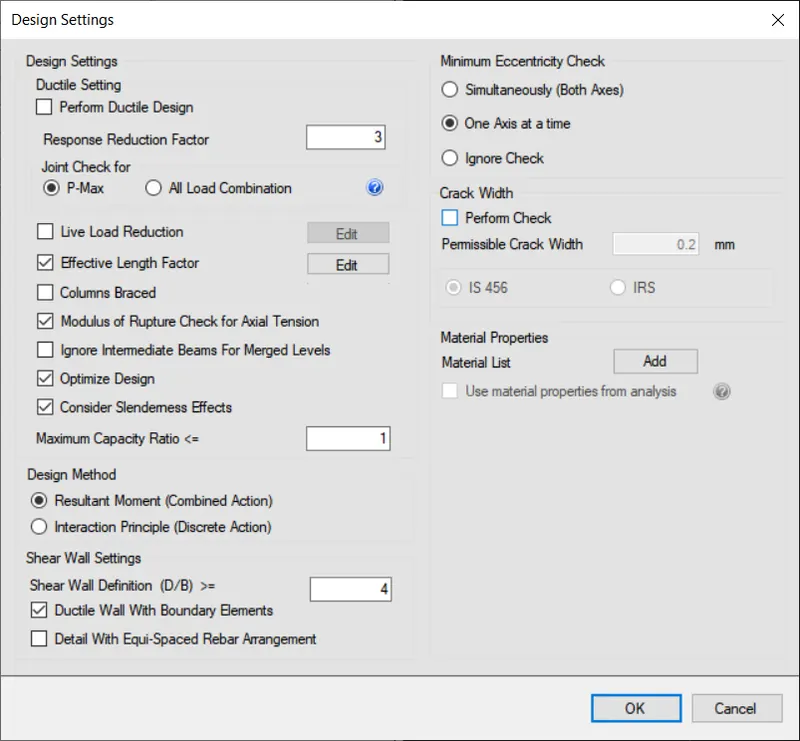
- Step 8:Define parameters:
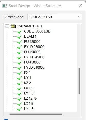
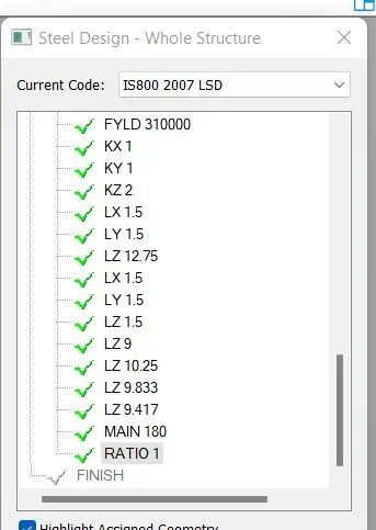
- Step 9:Define commands:
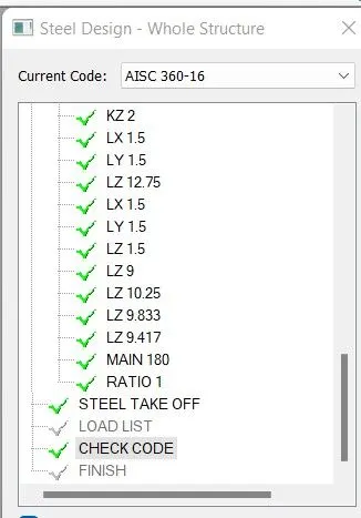
- Step 10:Run analysis:
3] Prepare DL, LL, WL and EQL load calculations as per IS 875 standards
Calculation of Design Loads
1)Calculation of Dead load:
UDL on Rafter (Main frame):
Weight of roof sheeting = 5 Kg/m2
Weight of sag rods and braces = 5 Kg/m2
Collateral load = 10 Kg/m2
Total load = 20 Kg/m2 = 0.2 KN/m2
UDL on Rafters:
Bay spacing = 6m
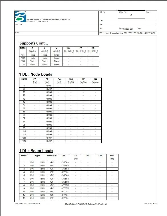
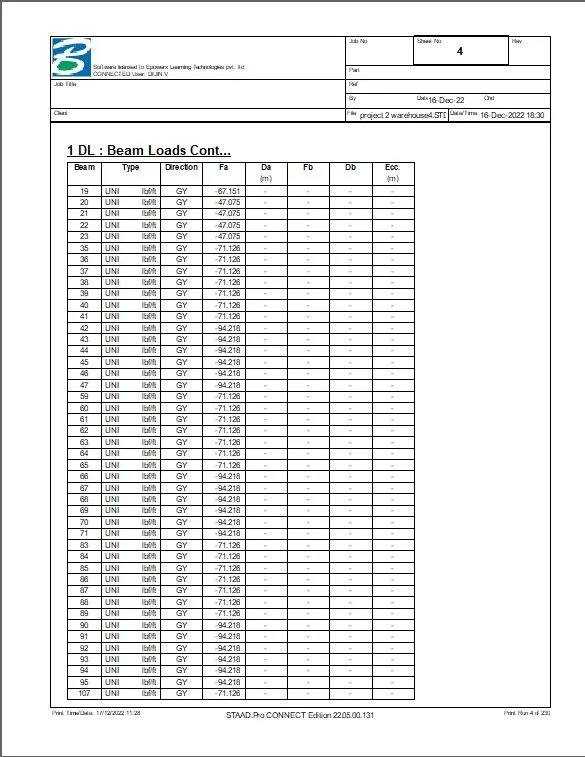
UDL = 0.2 X 6 = 1.2 KN/m
UDL on Rafters from purlin:
Choose suitable purlin section for weight of purlin (IS-811)
Say Z = 270 X 75 X 20 X 2.55 = 8.77 Kg/m
Weight on rafters from purlin = (Number of purlin X Length of purlin)/Length of rafter
= ( 5 X 6 X 8.77)/15
= 17.54 Kg/m = 0.175 KN/m
UDL on main frame = 1.2 + 0.175 = 1.375 KN/m
UDL on gable frame = 1.375/2 = 0.687 KN/m
UDL on Column (Main frame):
Weight of side wall sheeting = 5 Kg/m2
Weight of sag rod and braces = 5 Kg/m2
Load from sag rods & braces = 10 Kg/m2 = 0.1 KN/m2 = 6 X 0.1 = 0.6 KN/m
Weight of grit (270 X 75 X 20 X 2.55) = 8.77 Kg/m
Weight on column = (5 X 6 X 8.77)/6 = 43.85 Kg/m = 0.438 KN/m
Total Load = 0.6 + 0.438 = 1.038 KN/m
UDL on Column (Gable frame):
Total load = 1.038/2 = 0.565 KN/m
Load on wind column:
Load from sheet and sag rods = 0.1 X 6 = 0.6 kN/m
Weight of grits (230 X 75 X 20 X 2) = 6.32 KG/m
Load on wind column = (6X 6.32 X 6)/6 = 37.92 Kg/m = 0.38 KN/m
Total load = 0.6 + 0.38 = 0.98 KN/m
- Dead Load on eave strut & Gutter:
- Point load:-
Weight of Eave strut = CS 270 X 75 X 20 X 3.15 = 10.7 Kg/m
Weight of eave gutter = 0.25 X 0.25 X 0.001 = [0.25 + 0.25 + 0.25] X 0.001 X 7850
=5.89 Kg/m
Load due to eave strut & gutter = 10.7 + 5.89 = 16.59 Kg/m
Load due to eave strut & gutter (Main frame) = 16.59 X 6 = 99.54 Kg
= 0.995 KN
Load due to eave strut & gutter (Gable frame) =0.497 KN
2) Calculation of Live load:
Live load on roof = 0.75 KN/m2 (IS 875- II)
UDL on Rafter:
Main frame rafter = 0.75 X 6 = 4.5 KN/m
Gable frame rafter = 0.5 X 4.5 = 2.25 KN/m
Eave gutter (250 X 250 X 1mm)
Load due to weight of water in gutter:
Main frame = [0.25 X 0.25 X 9 X 6] = 3.375 KN
Gable frame = [0.5 X 3.375] = 1.687 KN
3) Calculation of wind load:
Basic wind speed = 50 m/s for Chennai.
K1 - 1.00
K2 - 1.0
K3 - 1.00
K4 - 1.15
Kd -0.9
Ka (Rafter) - 0.8 or as per tributary area.
Ka (Column) - 0.8245 or as per tributary area.
Ka (Purlin) - 0.9721 or as per tributary area.
Ka (Side Runner) - 0.978 or as per tributary area
Kc -0.9
Design wind pressure = pd = kd x ka x kc x 0.6 x (Vb x k1 x k2 x k3 x k4)^2= 0.652 kN/m2
But should not be less than 0.7 Pz = 0.7 x 1.006 = 0.704 kN/m2
Cpe - As per table 5 & 6 of IS: 875 (Part 3) – 2015
Cpe On wall:
|
Direction |
A |
B |
C |
D |
|
0 deg. |
0.7 |
-0.25 |
-0.6 |
-0.6 |
|
90 deg. |
-0.5 |
-0.5 |
0.7 |
-0.1 |
Cpe On Roof:
Roof angle = 2.86
|
Direction |
EF |
GH |
EG |
FH |
|
0 deg. |
-0.86 |
-0.4 |
||
|
90 deg. |
-0.8 |
-0.4 |
Cpi = 0.2
- Wind Load on Column in (+X)-direction:
Wind Load on Columns = (Cpe – Cpi) x A x Pd
Wind about X Direction + Cpi = (0.7 – 0.2) x 8 x 0.704 = 2.816 kN/m on Wall A
Wind about X Direction + Cpi = (-0.25 – 0.2) x 8 x 0.704 = -2.534 kN/m on Wall B
Wind about X Direction + Cpi = (-0.6 – 0.2) x 6.75 x 0.704 = -3.802 kN/m on Wall C & D
- Wind Load on Column in (-X)-direction:
Wind about X Direction - Cpi = (0.7 + 0.2) x 8 x 0.704 = 5.069 kN/m on Wall A
Wind about X Direction - Cpi = (-0.25 + 0.2) x 8 x 0.704 = -0.282 kN/m on Wall B
Wind about X Direction - Cpi = (-0.6 + 0.2) x 6.75 x 0.704 = -1.9 kN/m on Wall C & D
- Wind Load on Column in (+Z)-direction:
Wind about Z Direction + Cpi = (-0.5 – 0.2) x 8 x 0.704 = -3.942 kN/m on Wall A
Wind about Z Direction + Cpi = (-0.5 – 0.2) x 8 x 0.704 = -3.942 kN/m on Wall B
Wind about Z Direction + Cpi = (0.7 – 0.2) x 6.75 x 0.704 = 2.376 kN/m on Wall C
Wind about Z Direction + Cpi = (-0.1 – 0.2) x 6.75 x 0.704 = -1.425 kN/m on Wall D
Wind Load on Column in (-Z)-direction:
Wind about Z Direction - Cpi = (-0.5 + 0.2) x 8 x 0.704 = -1.689 kN/m on Wall A
Wind about Z Direction - Cpi = (-0.5 + 0.2) x 8 x 0.704 = -1.689 kN/m on Wall B
Wind about Z Direction - Cpi = (0.7 + 0.2) x 6.75 x 0.704 = 4.276 kN/m on Wall C
Wind about Z Direction - Cpi = (-0.1 + 0.2) x 6.75 x 0.704 = 0.475 kN/m on Wall D
- Wind Load on Rafters in (+X)-direction:
Wind Load on Rafters = (Cpe – Cpi) x A x Pd
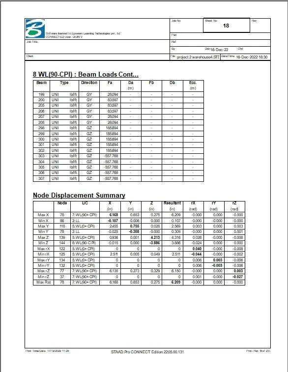
Wind about X Direction + Cpi = (-0.86 – 0.2) x 8 x 0.704 = -5.970 kN/m on Side A Rafter
Wind about X Direction + Cpi = (-0.4 – 0.2) x 8 x 0.704 = -3.378 kN/m on Side B Rafter
- Wind Load on Rafters in (-X)-direction:
Wind about X Direction - Cpi = (-0.86 + 0.2) x 8 x 0.704 = -3.716 kN/m on Side A Rafter
Wind about X Direction - Cpi = (-0.4 + 0.2) x 8 x 0.704 = -1.125 kN/m on Side B Rafter
- Wind Load on Rafters in (+Z)-direction:
Wind about Z Direction + Cpi = (-0.8 - 0.2) x 6.75 x 0.704 = -4.752 kN/m Side C Rafter
Wind about Z Direction + Cpi = (-0.4 - 0.2) x 6.75 x 0.704 = -2.851 kN/m Side D Rafter
- Wind Load on Rafters in (-Z)-direction:
Wind about Z Direction - Cpi = (-0.8 + 0.2) x 6.75 x 0.704 = - 2.851kN/m Side C Rafter
Wind about Z Direction - Cpi = (-0.4 + 0.2) x 6.75 x 0.704 = -0.950 kN/m Side D Rafter
- Wind Load on Canopy:
Cp - As per table 8 of IS: 875 (Part 3) – 2015
Roof Angle 2.86 deg.
Cp -ve = 1.08
Cp +ve = 0.35
Wind Load on Canopy (Upward) = 1.08 x 8 x 0.704 = 6.082 kN/m
Wind Load on Canopy (Downward) = 0.35 x 8 x 0.704 = 1.971 kN/m
- 4) Seismic Load:
As per IS: 1893 - 2016
Seismic zone - III - Z = 0.16
Rf - 4.0
I - 1.0
SS - 3.0
25% of Live Load on roof considered for calculation of seismic forces.
100% of collateral load on roof considered for calculation of seismic forces.
50% of (Live load + Collateral load) on mezzanine floor considered for calculation of seismic forces.
100% of Dead load considered for calculation of seismic force.
4] Design using MS – Excel
- Steel column
- Rafter
- Base plate
- Pedestal
- Z- purlin
1.DESIGN OF STEEL COLUMN:
Flange thickness = T = 12.7 mm.
Overall height of Column ISMB400 = h = 400 mm.
Clear depth between flanges = d = 400 – (12.7 x 2)
= 374.6 mm.
Thickness of web = t = 10.6mm.
Flange width = 2b = bf = 250 mm.
Hence, half Flange Width = b = 125 mm.
Self –weight = w = 0.822 kN/m.
Area of cross-section = A = 10466 mm2.
Radius of gyration about x = rx = 166.1 mm.
Radius of gyration about y = ry = 51.6 mm.
Type of section:
b/T = 125/12.7= 9.8 < 10.5
d/t =374.6/10.6 =35.3 < 42
(Table 3.1 of IS: 800)
Hence, cross-section can be classified as “COMPACT”.
Effective Sectional Area, Ae = 10,466 mm2
(Since there is no hole, (Clause 7.3.2 of IS: 800)
no reduction has been considered)
Effective Length:
As, both ends are pin-jointed effective length, KLx = KLy = 3m
- Slenderness ratios:
KLx/rx = 9000/166.1 =54.1
KLy/ry = 9000/51.6 =174.41
Non-dimensional Effective Slenderness ratio, λ">λ:
λ">λ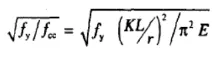
= (sqrt2.5X(174)^2)/(pi^2X2X10^5`= 3.83
Value of ϕ">ϕ from equation:

Hence, α">α = 0.34 for buckling class ‘b’ will be considered.
Hence, ϕ">ϕ= 0.5 x [1+0.34 x (0.654-0.2)+0.6542] = 0.791
Calculation of x:
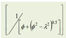 = 0.809
Calculation of fcd from the following equation:
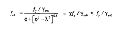
= 0.809 x 250/1.1 = 183.86 N/mm2
Factored axial load in kN.
pd = Ag fcd
= 10466 x 183.86/1000 = 1924.28 kN.
2. DESIGN OF RAFTER:
Span of Rafter = 6 m
Dead load = 18KN/m
Imposed load = 40KN/m
support bearing = 100mm
yield strength = 250N/mm2
- Design load calculation:
Factores load 1.5(DL+LL) =87 KN/m
Factores Bending moment = Wl28">
- Section modulus Required:
Z reqd = (65.25 x106106 x1.1) /250 =287100 mm3 = 287.1 cm3
- Section classification:
ISMB-200
A = 323.3 mm2
D = 200mm
B = 100mm
t = 5.7 mm
T = 10.8 mm
Ixx = 2235.4 cm4
Iyy = 150 cm4
Zp = 375.35 cm3
Moment of resistence of the cross-section:
Md =
= (1 x 375.35 x 250) / ( 1.1)
Md = 85.306 > 65.25 KN/m
3. DESIGN OF BASE PLATE:
Strength of concrete, Fcu = 40 N/mm2
Yield strength of steel, fy = 250 N/mm2
Material factor, γm">γm= 1.1 KN
Factoresl Load = 1500 KN
- Steel column section:
Thickness of flange, T = 12.7 mm
Area required:
Bearing strength of concrete = 0.4fcu = 0.4 x 40 = 16 N/mm2
= (1500x1000) /( 16)
= 93750 mm2
Let size of plate , Bplate = 450 mm
Dplate = 300 mm
Area of plate= 135000 mm2
projection on each side = a=b =25mm
W = (1500x1000) /( 450 x 300)
= 11.11 N/mm2
Therefore, Thickness of Base Plate, clause 7.4.3.1
ts= 7.3 mm < 12.7 mm
Size of Base plate 450 x 350 x 16 mm
4.DESIGN OF PEDESTAL:
Grade of concrete = 40 N/mm2
Load = 200 KN
Moment = 120 KN
Horizontal shear = 20 KN
Yield strength = 250 N/mm2
Length of base plate = 450 mm
Width of base plate = 350 mm
C/C distance of bolt in group-Z = 300 mm
C/C distance of bolt in group-X = 180 mm
Bearing strength of concrete Fc = 16 N/mm2
Depth of Column = 300 mm
Width of Column = 250 mm
- Anchor Bolt Details:
Dia of anchor bolts =24 mm
No:of anchor bolts in each side = 4
Total no. of anchor bolts, n = 8
Gross area of the bolt ;Asb' = 452.16 mm2
Net area of bolt 'Anb' = 352 mm2
Ultimate tensile strength of bolt 'fub' = 400 N/mm2
Fyb (anchor bolts) = 240 N/mm2
- Base plate Details:
Ultimate tensile strength of plate 'fu' = 490 N/mm2
Thickness of plate = 16 mm
Yield stress of plate = 330 N/mm2
- Anchor bolt design:
Area of the plate = 157500 mm2
Stress,
Stress, Maximum pressure =
= 10.6 N/mm2 < 16 Hence OK
Minimum pressure =
= -9.04 N/mm2 < 16 Hence OK
Centroid = = 242.89 mm
a =L/2-C/3 = 144.04 mm
e = (L-Ld) / 2 =75 mm
y = (L - C/3-e) = 294.04 mm
Tension in anchor bolt along the length of plate, FT = (Mz - Fa)/Y
= 364.38
Tension per bolt = 91 KN
Shear per bolt = 1.63 KN
Shear Check:
Factored shear force = Vsb = 1.63 KN
Vd,sb = 81290.9 N
= 81 KN
Factored shear force = 65.03 KN
Tensile Check:
Factored tensile force in bolt, Tb = 91.1 KN
Tensile strength of bolt:
Ts,b = Tn,b /
Td,b = 98.65 KN
Combined Unity Check:
Vsb/Vdb = 0.025
Tb/Tdb = 0.92
Unity check = 0.85 < 1, Hence OK
Anchor Bolt Length:
Bond strength in tension,
Anchor length required = Tb(3.14*
= 863.44 mm
Let Anchor Bolt Length = 900 mm
5.DESIGN OF Z-PURLIN:
Span of the purlin = 6 m
Spacing of purlin = 1.5 m
No. of sag rods = 1
Slope of the roof = 4.76 = 5 degree
Dead load:
Weight of sheeting = 6kg/m2
self weight of purlin = 4.22 kg/m2
Additional load = 10% = 0.42 kg/m2
Total Dead load = 0.106 kg/m2
Live load:
Live load on roof = 75 kg/m2
Wind Load:
Basic wind speed = 50 m/s
Terrain caterogy = 2
Building class = B
K1 = 1
K2 = 1
K3 = 1
Design wind speed, Vz = 57 m/s
Design wind pressure, Pz = 1949.9 m/s = 1.94 KN
Length of building, L = 50 m
Breadth of building, W = 30 m
Height of building, H = 10.25 m
Height of eaves, = 9 m
h/w = 0.34
L/w = 1.667
External Pressure Co-eeficient:
Maximum downward =Cpe = -0.4
Maximum upward =Cpe = -0.7
Internal Pressure Co-eeficient:
Maximum positive =Cpi = 0.5
Maximum negative =Cpi = -0.5
For Maximum upward wind force:
Max upward Cpe = - 0.7
Cpi = - 0.5
Cpe + Cpi = -1.2
Pz = 1.95
Wind Pressure for Purlin Design = - 2.339 KN/m2
For Maximum upward wind force:
Max upward Cpe = - 0.4
Cpi = - 0.5
Cpe+Cpi = -0.1
Pz = 1.95
Wind Pressure for Purlin Design = 0.195 KN/m2
Design Load Calculation:
Spacing of purlin = 1.5 m
Slope of roof = 5 degree
Total dead load = 0.096
DL Normal component = 0.144 KN/m
DL Tangential component = 0.013 KN/m
Total Live load = 0.75
LL Normal component = 1.121 KN/m
LL Tangential component = 0.098 KN/m
Total Wind load = -2.339
WL Normal component = - 3.496 KN/m
WL2 WL load = 0.195 KN/m
WL Normal component = 0.291 KN/m
Maximum Normal component = DL+LL = 1.265 KN/m
Purlin section:
Selected section Z200 x 6 x 2.3
Area = 8.07 cm2
Weight of purlin = 6.335 kg/m.
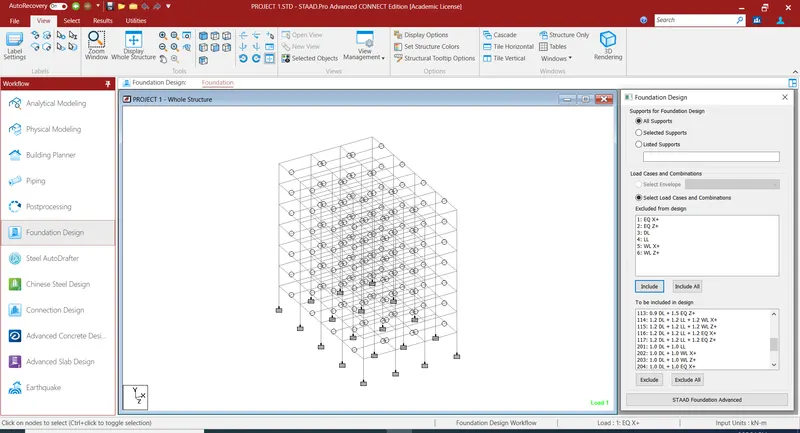
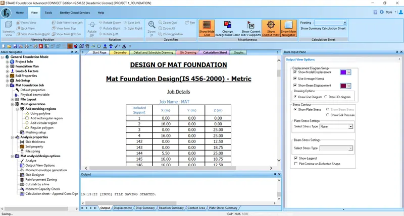
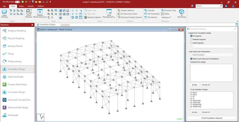
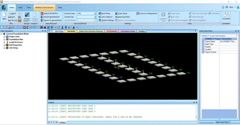
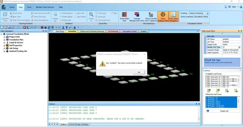
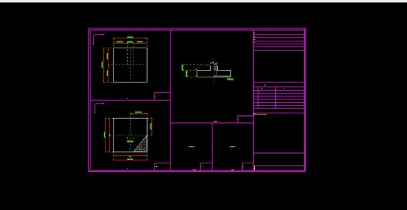
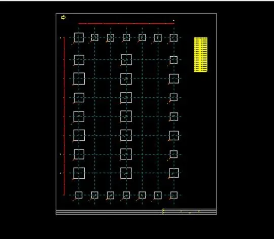
1] Design Foundations using STAAD Foundation.
Click on Staad foundation:
2. Design a simply supported gantry girder to carry electric overhead travelling crane
Given:
Span of gantry girder = 7 m
Span of crane girder = 9 m
Crane capacity = 250 kN
Self-weight of trolley, hook, electric motor etc. = 40 kN
Self-weight of crane girder excluding trolley = 100 kN
Minimum hook approach = 1.0 m
Distance between wheels = 3 m
Self-weight of rails = 0.2 kN/m.
Solution:
Step:-1
Maximum moment due to vertical load
Weight of trollley + Crane capacity = 40 + 250 = 290 kN
Self-weight of crane girder excluding trolley = 100 kN
For maximum reaction on gantry girder, the moving load should be as close the gantry girder as possible.
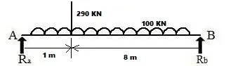
Ra=
This load is transferred to gantry girder, through two wheels, the wheel base being 3m.
So load on gantry girder from each wheel = 307.77/2 = 158.88 KN
Factored load = 158.88 x 1.5 =230.83 KN
Maximum moments due to moving loads occur under a wheel when the c.g of wheel load.
RD= 230.83 x (3-1.5-0.75) + 230.83 x (3+0.75)/7 = 148.40 KN
Max. moment, Me = 148.40 x 2.25 = 333.90 KNm.
Moment due to impact = 0.25 x 333.90 = 83.47 KNm.
Assume self weight of girder = 2KNm.
Dead load due to self weight + rails = 2+0.2= 2.2 KNm.
Factored Dead Load = 2.2 x 1.5 = 3.3 KNm.
Moment due to Dead Load =
Factored moment due to all vertical loads,
Mz = 333.90 + 83.47 + 20.21 = 437.58 KNm.
Step :- 2
Maximum moment due to Lateral force:
Horizontal force transferred to rails = 10% of weight of trolley plus load lifted = (10/100) x (250+40) = 29 KN
This is distributed over 4 wheels.
So, horizontal force on each wheel = 29/4 = 7.25 KN
Factored horizontal force on each wheel = 1.5 x 7.25 = 10.875 KN
For maximum moment in gantry girder the position of loads is same as earlier except that it is horizontal, hence by proportioning we get.
My = (10.875/230.83) x 333.90 = 15.73 KNm.
Step :- 3
Shear force:
Vertical shear due to wheel loads = 230.83 + (230.83 x 3) / 7 = 329.75 KN
Step :- 4
Priliminary Section:
Minimum economic depth, L/12 = 7000/12 = 583.33 mm
Width of the compression flange may be taken as (1/40) to (1/30) of span;
So, flange width can be taken as, L/40 = 7000/40 = 175 mm to L/30 = 7000/30 = 233.33 mm.
Required, Zp = 1.4 x M/fy =
Let us try a ISMB 600 with ISMC 400 on compression flange.
Step :- 5
| ISMB | 600 @1.22 kN/m. |
| A | 15600 sq.mm. |
| h | 600 mm. |
| b | 210 mm. |
| tf | 20.3 mm. |
| tw | 12 mm. |
| Izz | 91800 X |
| Iyy | 2650 X |
| R | 20 mm. |
| ISMC | 400 @0.49 kN/m. |
| A | 6380 sq.mm. |
| h | 400 mm. |
| b | 100 mm. |
| tf | 15.3 mm. |
| tw | 8.8 mm. |
| Izz | 15200 X |
| Iyy | 508 X |
| Cyy | 2.42 mm. |
Step :-6
Let the distance of N>A> from the tension range by y:
388.93 mm.
Izz = 1348.13x10^6mm^4
Zez = 3466240mm^3
For compression flange about y-y axis
I = 16766.7x10^4mm^4
Zey = 838333mm^3
Total area of section = 21980mm^2
Let plastic N>A> be at a distance
Yp = 580.88mm
Zpz = 4410317mm^3
For top flange Zpy = 1078488mm^3
Step :- 7
Section classfication:
For ISMB b/t = 4.90
< 9.4
d/t = 43.28
< 84
For ISMC b/t = 5.96
< 9.4
Hence section is plastic
Step :- 8
Check for local moment capacity:
Local moment capacity for bending in vertical plane
Mdz = fyZp/1.1
= 1002.34kNm
Mdz = 1.2Zefy/1.1
= 945.34kNm
For top flange
Mdy = 245.11kNm
Mdy = 228.64kNm
In the above whichever the minimum value is taken
Mdz = 945.34kNm
Mdy = 228.64kNm
Step : 9
Check for combined local capacity :
(812.99/945.34)+(18.35/228.64)<1
0.947<1
Step : 10
Check for buckling resistance :
Md = βbZpfbd
βb = 1
Lt = 7000mm
E = 200000N/mm^2
hf = 597.5mm
Iy = 17850x10^4mm^4
A = 21980mm^2
ry = 90.12mm
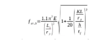
fcr,b = 417.43N/mm^2
λ = 0.744
φ = 0.95
= 0.97N/mm^2
fbd = 166.591
Mdz = 734.72kNm
Mdy = 202.84kNm
Hence 1.20>1
Hence section is unsafe against torsional buckling
Step : 11
Check for shear:
Vz = 714.59kN
Shear capacity = Avfyw/(3^0.5x1.1)
= 944755N
= 944.755kN
> 714.59
Now = 566.853kN
Low shear
Step : 12
Check for web buckling:
b = 175mm
n1 = 232.6mm
d = 519.4mm
t = 12mm
= 104.746
Fcd = 128.6N/mm^2
Buckling resistance = 629008kN > 714.59kN
Step : 13
Check for deflection at working load:
Vertical deflection:
Serviceability vertical wheel load = 251kN
Deflection at mid span a = 2000mm
Izz = 1348.13x10^5mm^4

δ = 25.32mm
Horizontal deflection
I = 16766.65x10^4mm^4
δ = 4.88mm
L/750 = 9.33mm
Unsafe in vertical direction but Safe in lateral direction.