Project 1
AIM
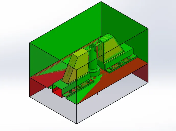
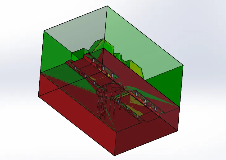
Is to create the core and cavity blocks with proper dimensions for the given model and create ejector pins and sliders.
PROCEDURE
- First analysis the given plastic component by using Draft Analysis option for the correct Tooling direction.
- After analysing if there is no draft give draft for 1 deg by using Draft option.
- After giving draft use Scale option to increase the shrinkage of the component and shrinkage value is given as per the data.
- After scaling use Parting Line option to indentify the line in given plastic component to separate Core and Cavity.
- If there is holes in the component use Shut Off Surface option to close the holes.
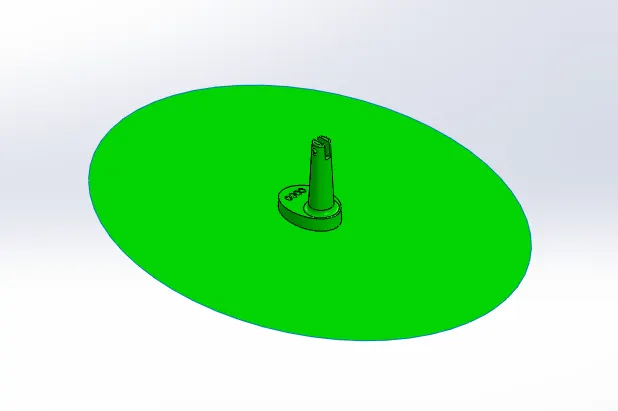
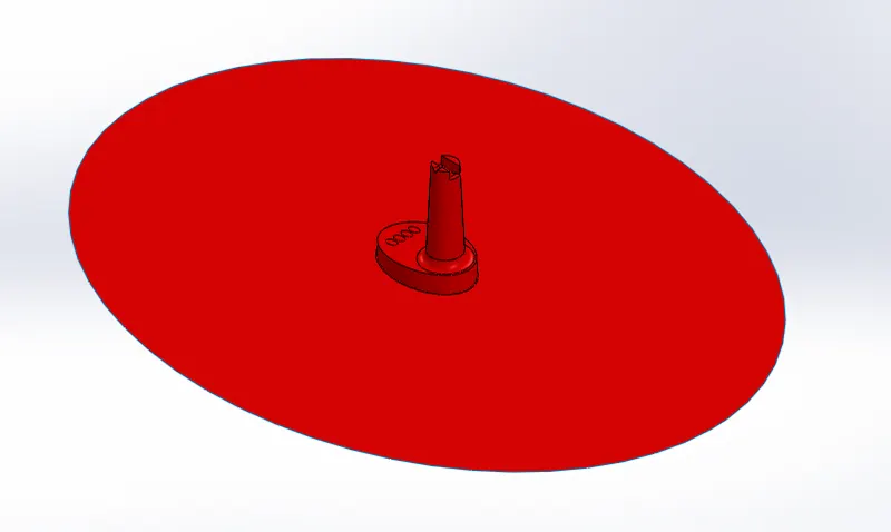
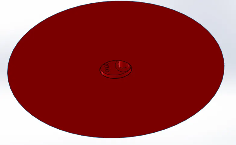
- After separating the core and cavity colour will change Green is Cavity and Red is Core and folder is created in the feature tree.
- Create a Parting Surface by creating a rectangle sketch and use Planer Surface and cut the required surface by using Trim Surface option.
- To make a copy of the parting surface use Move/Copy Bodies option it will be in Direct Editing
- To coimbine core and cavity with the parting surface use Knit Surface option.
- To create a block create a rectangle sketch and use Extruded Boss/Base option for extruding the sketch.
- Again use Move/Copy Bodies option for the block.
- To cut the required position of the block use Cut with Surface option for both core and cavity and give colour to the block and select the required side and change into Transparency.
- For creating Ejection Pin create a sketch using Circle near the ribs and after creating use Circle Pattern in necessary areas.
- After creating use Core option to extend upto the surface and Relief should be given for that create a circle and offset and cut using Cut Extrude option as per the given data.
- Create a plane in the undercut area by using Referance Plane option and create a sketch by using Convert Entities option.
- After creating use Split option to split the cavity and slider after spliting it show as split 1 and 2.
- In slider create remaining sketch and extrude using Extruded Boss/Base option.
- In between split and undercut there will a gap for that again use Extruded Boss/Base option.
- Inside the split 2 there will some surfaces to remove use Cut Extruded option.
- For the slider create a sketch as per the given data as use cut and extrude by using Cut Extruded and Extruded Boss/Base option.
- Slider should be fit in the Core and Cavity mold block for that take a copy of the slider and use Combine option and select subtract option.
- To close the holes and gaps create a rectangle sketch and extrude using Extruded Boss/Base option and for gaps use Move Face option and select offect option.
- In assembly create a New Part and name as Slider and after creating import the slider part in the slider folder by going to insert - feature - imported.
- In Core block slider movement should be available for that create a sketch and cut the area by using Cut Extruded option.
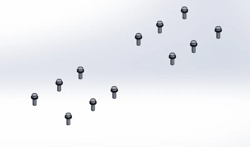
- For washers and bolt create a rectangle sketch as per the data given and extrude it and some position is removed in the slider for that create a sketch and use Cut Exturded option.
- Give fillets to the edges in the core, cavity and the slider by using Fillet option.
- Create a New Part by using Insert Components option for the Washers and Bolts.
- Create a Circle sketch for the washers and bolts and use extrude it as per the given data and mirror for other side by using Mirror option and more cicle use Liner pattern option.
- In cavity create a circle sketch and cut using Cut Extruded option for the Bolt.
- For Locking Mechanism create a sketch in the core as per the given data as create another sketch in the slider as cut using Cut Extruded option.
- Repeat these process for the another side of the core and cavity.
- At the end of the core and cavity block give some relief by using Move option.
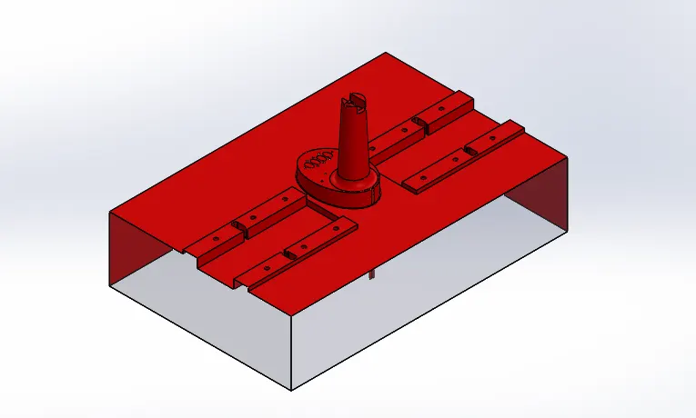
IMAGES OF CAVITY
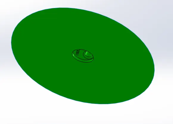
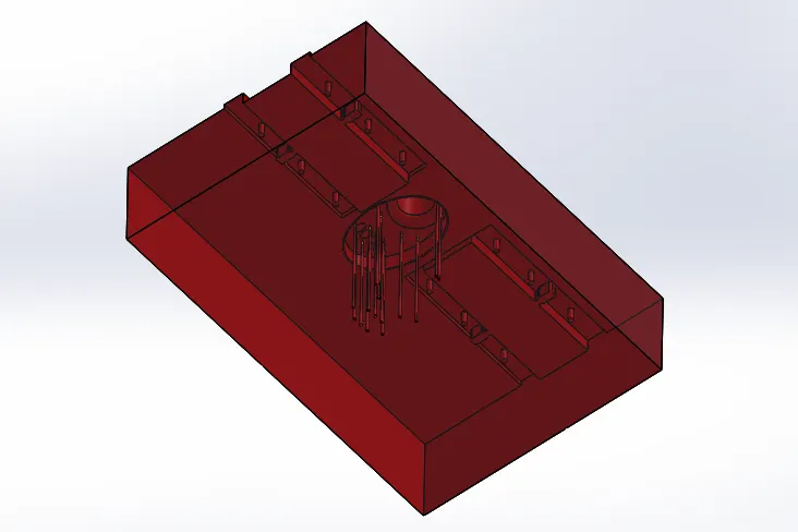
IMAGES OF CORE
FEATURE TREE OF CORE AND CAVITY SURFACE
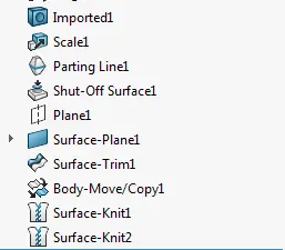
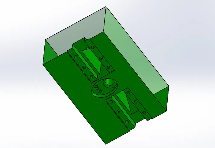
IMAGES OF CAVITY STEEL
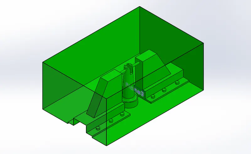
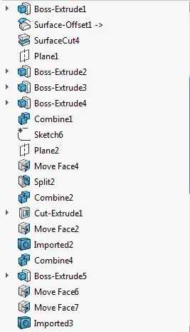
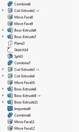
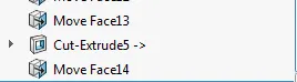
FEATURE TREE
IMAGES OF CORE STEEL
FEATURE TREE
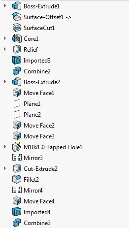
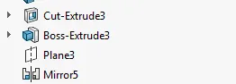
IMAGE OF EJECTOR PIN
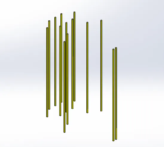
IMAGE OF SLIDERS
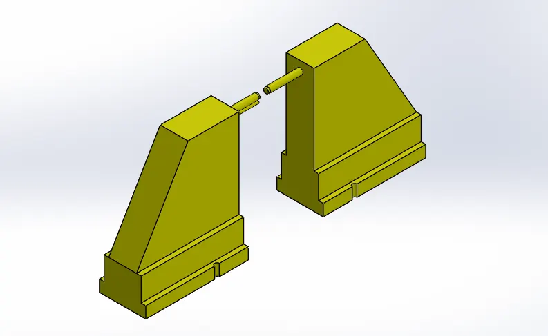
IMAGE OF WASHERS AND BOLTS
OVERALL MOLD DESIGN