Project 1
Project 1 :
Project 1 deals with demonstrating a proof of concept of engine management systems. In this project following design should be implemented using Arduino Uno to have a setup that demonstrates the working model of a typical engine position management system inside an automobile.
a)
- Camshaft arrangement: Design a stand-alone camshaft arrangement with an Arduino Uno. Connect a DC Motor to Arduino Uno. To the shaft of the DC Motor connect an egg-shaped cardboard. This DC motor along with egg shaped cardboard acts as the cam lobe. Place a proximity sensor to sense the movement of the nose of cam lobe. Connect one more DC Motor and egg-shaped cardboard to the same Arduino Uno to represent a dual overhead camshaft setup. Place another proximity sensor to this setup. The proximity sensors in this arrangement will act as camshaft sensor. Connect two LEDs to represent inlet valves and outlet valves. Glowing of LED can be considered as opening of respective valves. Now design a software for this system to represent the working of camshaft arrangement. [HINT: A typical camshaft arrangement will have cam lobes, camshaft sensors and controls the movement of inlet and outlet valves. The two motors in this system should rotate the egg-shaped cardboard continuously. Whenever, the nose of the cam lobe comes near the camshaft sensor it should open the valves. Select one motor, cardboard and proximity sensor setup for inlet valve and the other for outlet valve. Inside an automobile engine, the nose of the cam lobe is used to open the inlet and outlet valves. So, whenever the nose is detected by the proximity sensor the LEDs representing the inlet valve and the outlet valve should glow. The LEDs should stay OFF otherwise.
Solution : DC Motor Interfacing with Arduino UNO
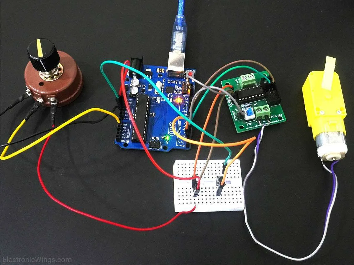
Overview of DC Motor
DC MOTOR :
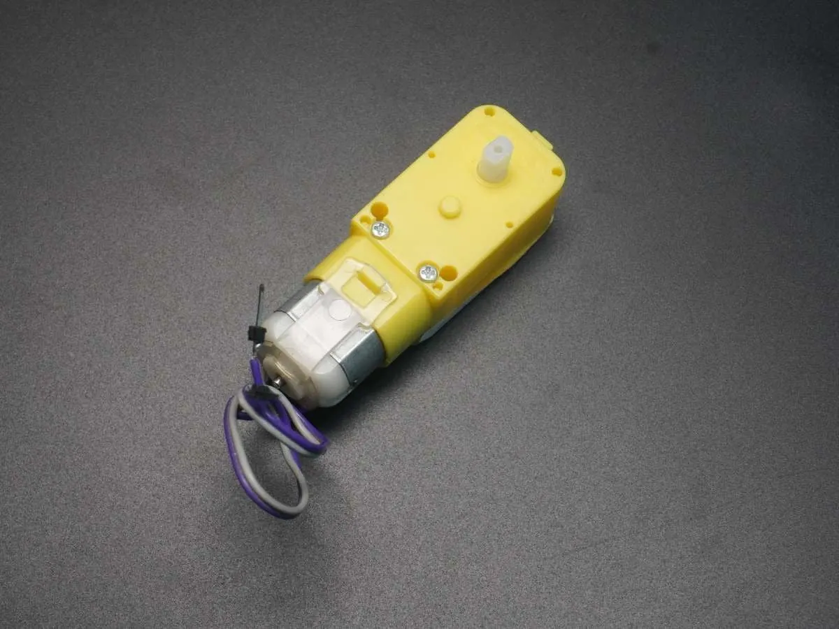
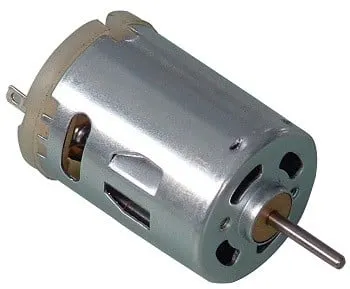
DC motor converts electrical energy in the form of Direct Current into mechanical energy in the form of rotational motion of the motor shaft.
The DC motor speed can be controlled by applying varying DC voltage; whereas the direction of rotation of the motor can be changed by reversing the direction of current through it.
For applying varying voltage, we can make use of PWM technique.
For reversing the current, we can make use of H-Bridge circuit or motor driver ICs that employ the H-Bridge technique.
For more information about DC motors and how to use them, H-Bridge circuit configurations, and PWM technique, refer the topic DC Motors in the sensors and modules section.
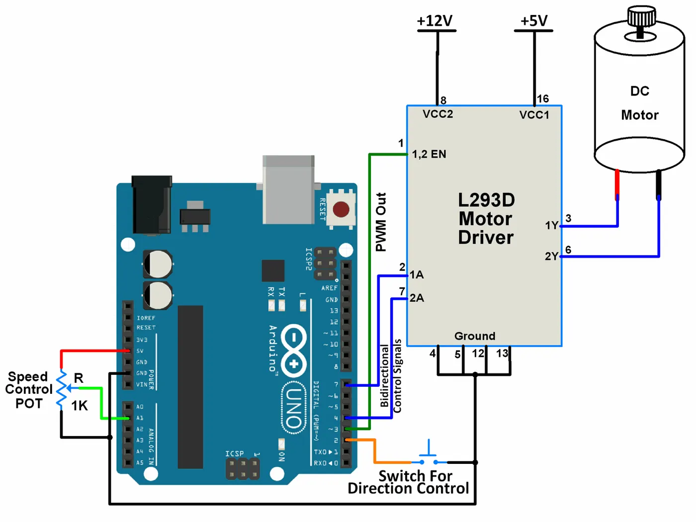
Connection Diagram of DC Motor with Arduino
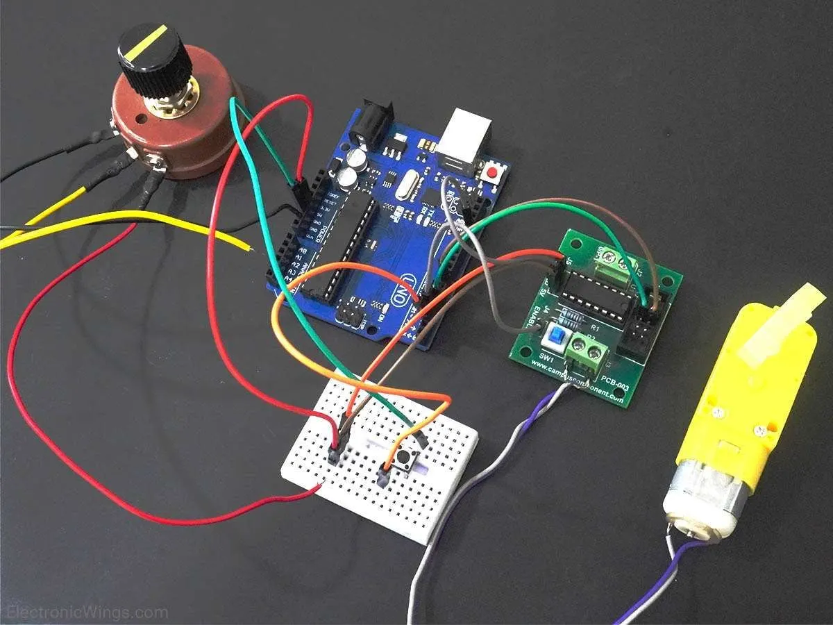
Example
Here, we are going to control the speed and rotational direction of DC motor using Arduino Uno.
Here, a potentiometer is used as a means for speed control and an input from a tactile switch is used to change the direction of the motor.
L293D motor driver IC is used for controlling the direction of the motor.
PWM wave generated on the Arduino UNO is used to provide a variable voltage to the motor through L293D. In Arduino, analogWrite function is used to generate PWM wave.
Direction and Speed Control of DC Motor Code for Arduino
const int POT_input = A1;   /* assign ADC Channel */
bool d1 = HIGH;
bool d2 = LOW;

void setup() {
  pinMode(4, OUTPUT);  /* Motor control pin 1 */
  pinMode(7, OUTPUT);  /* Motor control pin 2 */
  pinMode(3, OUTPUT);  /* PWM pin for Speed Control */
  pinMode(2, INPUT_PULLUP);  /* Interrupt pin for direction control */
  attachInterrupt(digitalPinToInterrupt(2), motor, FALLING);	/* Interrupt on falling edge on pin 2 */
}

void loop() {
  int pwm_adc;
  pwm_adc = analogRead(POT_input); /* Input from Potentiometer for speed control */
  digitalWrite(4,d1);
  digitalWrite(7,d2);
  analogWrite(3, pwm_adc / 4);
}

void motor(){
  d1 = !d1;
  d2 = !d2;
  _delay_ms(200);
}
Functions Used
1. digitalPinToInterrupt(pin)- This function is used to declare the digital pin as an interrupt pin.
- Example:
digitalPinToInterrupt(2)is used to declare digital pin 2 as an interrupt pin. - On UNO board, only pins 2 and 3 can be configured as interrupt pins. Hence, argument to this function can only be pin 2 or pin 3.
2. attachInterrupt(digitalPinToInterrupt(pin), ISR, mode)- This function is used to configure the mode of interrupt event and declare the ISR for that interrupt. The interrupt event and ISR is for the interrupt pin declared by the function digitalPinToInterrupt(pin).
- ISR in this function is the name of the ISR that will be used for this interrupt.
- mode defines when the interrupt will be triggered. There are four modes available to choose from :
-LOW: trigger the interrupt whenever the pin is low.
-CHANGE: trigger the interrupt whenever the pin changes value.
-RISING: trigger when the pin goes from low to high.
-FALLING: trigger when the pin goes from high to low. - Example,
attachInterrupt(digitalPinToInterrupt(2), motor, FALLING)configures digital pin 2 as an interrupt pin with ISR named motor and which generates interrupt for every falling edge event on pin 2.
3. analogWrite(pin,value)- This function is used for generating PWM on PWM digital pins(pins 3,5,6,9,10,11 for Arduino UNO).
- value can be any number between 0 to 255. 0 being 0% duty cycle and 255 being 100% duty cycle.
b)
/*
	L298N Motor Demonstration
	L298N-Motor-Demo.ino
	Demonstrates functions of L298N Motor Controller

	DroneBot Workshop 2017
	http://dronebotworkshop.com
*/


// Motor A

int enA = 9;
int in1 = 8;
int in2 = 7;

// Motor B

int enB = 3;
int in3 = 5;
int in4 = 4;

void setup()

{

  // Set all the motor control pins to outputs

  pinMode(enA, OUTPUT);
  pinMode(enB, OUTPUT);
  pinMode(in1, OUTPUT);
  pinMode(in2, OUTPUT);
  pinMode(in3, OUTPUT);
  pinMode(in4, OUTPUT);

}

void demoOne()

{

  // This function will run the motors in both directions at a fixed speed

  // Turn on motor A

  digitalWrite(in1, HIGH);
  digitalWrite(in2, LOW);

  // Set speed to 200 out of possible range 0~255

  analogWrite(enA, 200);

  // Turn on motor B

  digitalWrite(in3, HIGH);
  digitalWrite(in4, LOW);

  // Set speed to 200 out of possible range 0~255

  analogWrite(enB, 200);

  delay(2000);

  // Now change motor directions

  digitalWrite(in1, LOW);
  digitalWrite(in2, HIGH);
  digitalWrite(in3, LOW);
  digitalWrite(in4, HIGH);

  delay(2000);

  // Now turn off motors

  digitalWrite(in1, LOW);
  digitalWrite(in2, LOW);
  digitalWrite(in3, LOW);
  digitalWrite(in4, LOW);

}

void demoTwo()

{

  // This function will run the motors across the range of possible speeds
  // Note that maximum speed is determined by the motor itself and the operating voltage

  // Turn on motors

  digitalWrite(in1, LOW);
  digitalWrite(in2, HIGH);
  digitalWrite(in3, LOW);
  digitalWrite(in4, HIGH);

  // Accelerate from zero to maximum speed

  for (int i = 0; i < 256; i++)

  {

    analogWrite(enA, i);
    analogWrite(enB, i);

    delay(20);

  }

  // Decelerate from maximum speed to zero

  for (int i = 255; i >= 0; --i)

  {

    analogWrite(enA, i);
    analogWrite(enB, i);

    delay(20);

  }

  // Now turn off motors

  digitalWrite(in1, LOW);
  digitalWrite(in2, LOW);
  digitalWrite(in3, LOW);
  digitalWrite(in4, LOW);

}

void loop()

{

  demoOne();

  delay(1000);

  demoTwo();

  delay(1000);

}
*/

// Motor A

int enA = 9;
int in1 = 8;
int in2 = 7;

// Motor B

int enB = 3;
int in3 = 5;
int in4 = 4;

// Joystick Input

int joyVert = A0; // Vertical
int joyHorz = A1; // Horizontal

// Motor Speed Values - Start at zero

int MotorSpeed1 = 0;
int MotorSpeed2 = 0;

// Joystick Values - Start at 512 (middle position)

int joyposVert = 512;
int joyposHorz = 512;


void setup()

{

  // Set all the motor control pins to outputs

  pinMode(enA, OUTPUT);
  pinMode(enB, OUTPUT);
  pinMode(in1, OUTPUT);
  pinMode(in2, OUTPUT);
  pinMode(in3, OUTPUT);
  pinMode(in4, OUTPUT);

  // Start with motors disabled and direction forward

  // Motor A

  digitalWrite(enA, LOW);
  digitalWrite(in1, HIGH);
  digitalWrite(in2, LOW);

  // Motor B

  digitalWrite(enB, LOW);
  digitalWrite(in3, HIGH);
  digitalWrite(in4, LOW);

}

void loop() {

	// Read the Joystick X and Y positions

	joyposVert = analogRead(joyVert);
	joyposHorz = analogRead(joyHorz);

	// Determine if this is a forward or backward motion
	// Do this by reading the Verticle Value
	// Apply results to MotorSpeed and to Direction

	if (joyposVert < 460)
	{
		// This is Backward

		// Set Motor A backward

		digitalWrite(in1, LOW);
		digitalWrite(in2, HIGH);

		// Set Motor B backward

		digitalWrite(in3, LOW);
		digitalWrite(in4, HIGH);

		//Determine Motor Speeds

		// As we are going backwards we need to reverse readings

		joyposVert = joyposVert - 460; // This produces a negative number
		joyposVert = joyposVert * -1;  // Make the number positive

		MotorSpeed1 = map(joyposVert, 0, 460, 0, 255);
		MotorSpeed2 = map(joyposVert, 0, 460, 0, 255);

	}
	else if (joyposVert > 564)
	{
		// This is Forward

		// Set Motor A forward

		digitalWrite(in1, HIGH);
		digitalWrite(in2, LOW);

		// Set Motor B forward

		digitalWrite(in3, HIGH);
		digitalWrite(in4, LOW);

		//Determine Motor Speeds

		MotorSpeed1 = map(joyposVert, 564, 1023, 0, 255);
		MotorSpeed2 = map(joyposVert, 564, 1023, 0, 255);

	}
	else
	{
		// This is Stopped

		MotorSpeed1 = 0;
		MotorSpeed2 = 0;

	}

	// Now do the steering
	// The Horizontal position will "weigh" the motor speed
	// Values for each motor

	if (joyposHorz < 460)
	{
		// Move Left

		// As we are going left we need to reverse readings

		joyposHorz = joyposHorz - 460; // This produces a negative number
		joyposHorz = joyposHorz * -1;  // Make the number positive

		// Map the number to a value of 255 maximum

		joyposHorz = map(joyposHorz, 0, 460, 0, 255);


		MotorSpeed1 = MotorSpeed1 - joyposHorz;
		MotorSpeed2 = MotorSpeed2 + joyposHorz;

		// Don't exceed range of 0-255 for motor speeds

		if (MotorSpeed1 < 0)MotorSpeed1 = 0;
		if (MotorSpeed2 > 255)MotorSpeed2 = 255;

	}
	else if (joyposHorz > 564)
	{
		// Move Right

		// Map the number to a value of 255 maximum

		joyposHorz = map(joyposHorz, 564, 1023, 0, 255);


		MotorSpeed1 = MotorSpeed1 + joyposHorz;
		MotorSpeed2 = MotorSpeed2 - joyposHorz;

		// Don't exceed range of 0-255 for motor speeds

		if (MotorSpeed1 > 255)MotorSpeed1 = 255;
		if (MotorSpeed2 < 0)MotorSpeed2 = 0;

	}


	// Adjust to prevent "buzzing" at very low speed

	if (MotorSpeed1 < 8)MotorSpeed1 = 0;
	if (MotorSpeed2 < 8)MotorSpeed2 = 0;

	// Set the motor speeds

	analogWrite(enA, MotorSpeed1);
	analogWrite(enB, MotorSpeed2);

}
c)
- Inside Cylinder Arrangement: Design a stand-alone inside of an automobile cylinder arrangement. Design a slider-crank mechanism with the help of cardboard. Connect the circular wheel of the slider-crank arrangement to Arduino Uno with a DC Motor. This setup represents crankshaft-piston arrangement inside an engine. Connect a temperature and pressure sensor to this Arduino Uno to measure the temperature and pressure inside the cylinder. Connect one LED to Arduino Uno representing spark plug or fuel injectors inside an engine for gasoline and diesel engines respectively.
Solution:
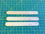
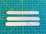
You'll build the slider crank assembly from three craft sticks. The mechanism consists of these key parts:
- Crank shaft
- Connecting rod
- Slider (also known as a piston in some mechanisms)
We'll drive the crank shaft with the servo motor, and the slider will translate back and forth along a guide block made of cardboard.
Start by getting the three craft sticks.
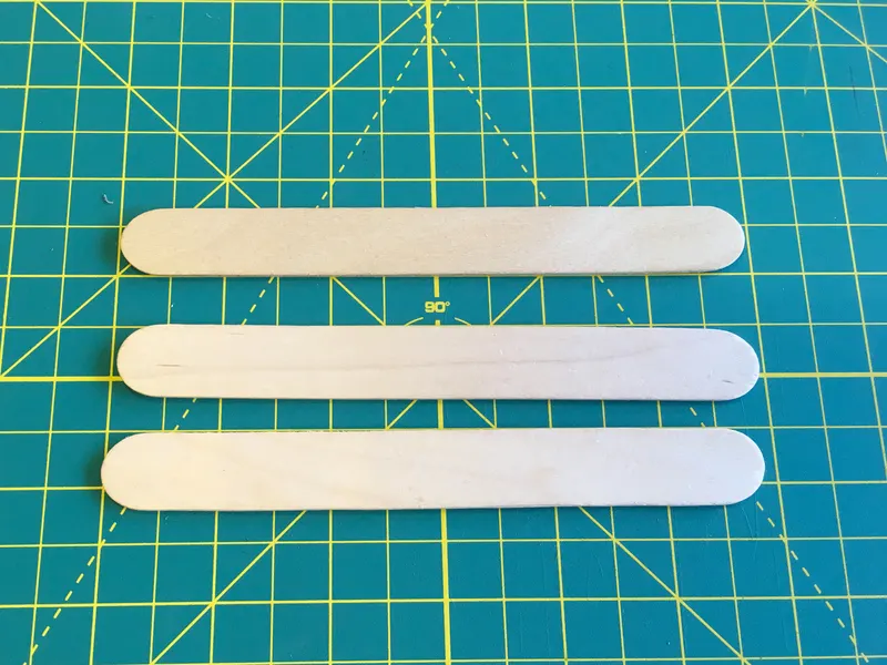
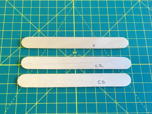
Prep the Linkages
Here, they've been marked 'CS' for crank shaft, 'CR' for connecting rod, and 'P' for piston (this is the same piece as the slider).
- Mark a point 'A' near one end of the crank shaft
- Measure and mark a line 2-1/4" from the A pivot end of the crank shaft
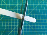
- Cut the crank shaft to length
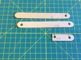
- Punch a hole at each end of the crank shaft
- Punch a hole at each end of the connecting rod
- Punch a hole at one end of the pivot or slider
Next, we'll join the linkages using the brass paper fasteners.
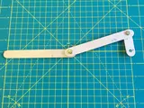
- Fasten the Pivots
- Overlap the connecting rod on top of the B pivot end of the crank shaft, then join them with a paper fastener
- Spread the fastener tabs wide on the other side, then fold them in
- Repeat this process, overlapping the connecting rod D pivot with the E pivot of the piston/slider and then fastening it as shown
Use hot melt glue to adhere the A pivot end of the crank shaft to the large, round servo horn. Once it cools, press it onto the servo's splined shaft.
Use the horn to rotate the servo shaft to the far left and then remove, rotate, and reattach the horn to the shaft so the linkages are in a straight line to the left as shown.
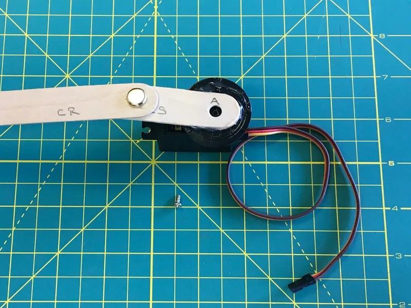
You can secure the servo horn to the servo shaft with the small screw and a screwdriver.
You'll power and control the servo with the Circuit Playground Express. Plug the three alligator clip jumper wires into the servo cable housing:
- Black to Brown
- Red to Orange
- Yellow to Yellow