Project 1
*Objective-
The project's goal is to generate a flat view drawing in CATIA V5 and route the wire harness on a specific Bugatti V16 engine. Routing the harness requires consideration of all packaging regulations. Additionally, design work should show off industry best practises. All the required information, such as clearance and clipping/clamping choice.
1)The 16-valve Bugatti engine is depicted in the above figure with 8 cylinders on the right side and 8 cylinders on the left.
2)There are 16 injectors in all, 8 of which are used for the 8 cylinders on the right side and 8 for the additional 8 cylinders on the left.
3)There are a total of 20 sensors that need to be electrically linked, including 4 camshaft sensors.
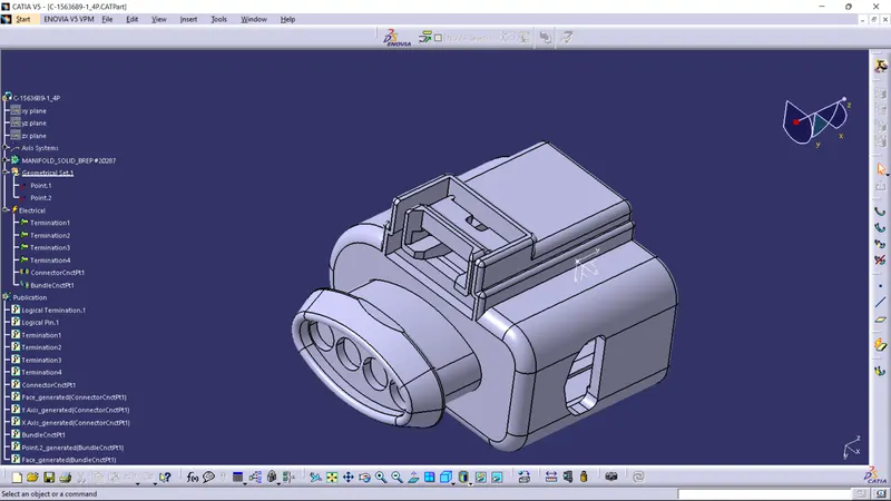
4)The engine's fuel injectors typically employ 4-pole connectors.
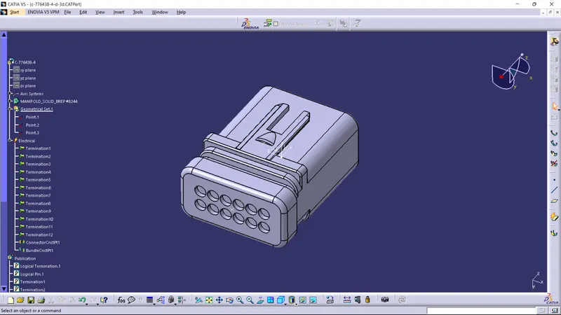
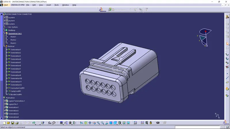
5)The engine will also have a connector for interconnecting it with other components of the vehicle. An interconnection connector will be a 12-pole electrical connector with a mounting clip.
6)The 16 valve Bugatti Engine should have a bend ratio of 1.4 for the entire bundle of segments.

-
Assumptions-
- Give out clips or clamps as needed.
- When constructing the wire harness, make sure there are no flaws. To prevent a failing casing, more clips or clamps may be employed.
- Give more room if necessary. A 5–15% slack is adequate.
- Avoid routing around jagged edges, or else cover the harness with protection.
- Observe the clearance distance and keep the harness away from components that produce heat.
- Depending on the temperature outside, protection should be given as needed.
- Avoid directly supporting the harness on the engine's fuel lines.
- If necessary, use plastic guiding channels.
- Branch length needs to be at least 50mm.
- Two branch points should be spaced apart by at least 50mm.
- Clip and branch point should be spaced apart by at least 25mm.
- Avoid too many sheet metal brackets on the engine.
- The wire harness need to be simple to access and put together.
- Make sure the positions you are defining while utilising dummy connectors are useful. For the wire harness routing, bundle sizes and other placements can be appropriately described.
*Step 1- Creating Context Assembly
- The primary assembly, as depicted in the above figure, is a Context Assembly for Engine Harness.
Engine assembly information for the Bugatti V16 engine and the engine harness geometrical bundle assembly will be included in a context assembly.
When necessary, sheet metal brackets are added to the context assembly.
*12POLE CONNECTOR-
*4 POLE CONNECTOR-
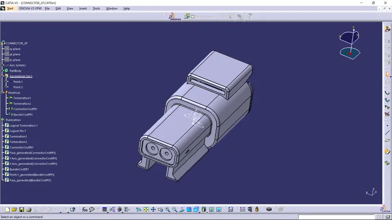
*2 POLE CONNECTOR-
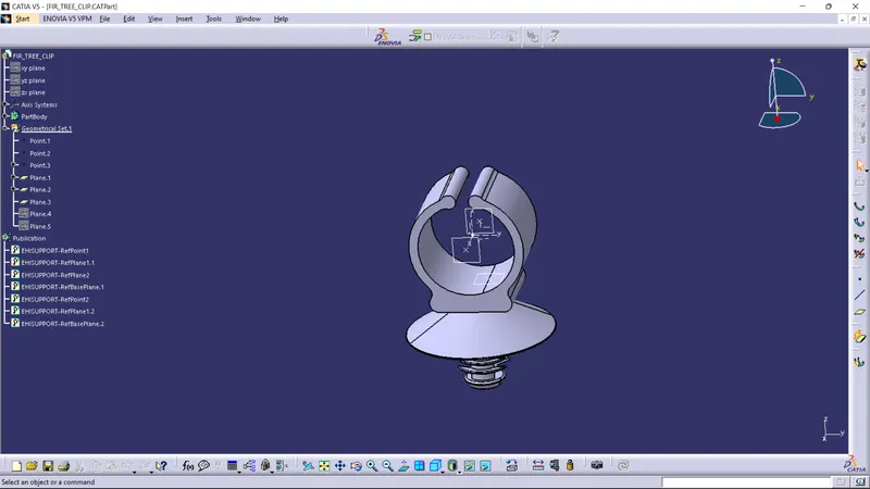
*FIR TREE CLIP-
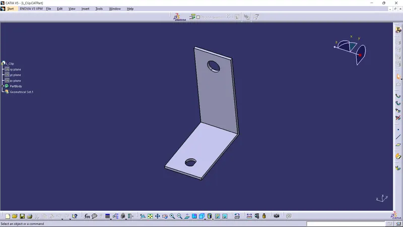
*L_CLIP-
*Step 2 To define 4-pole connector electrically
All connectors, including those with two, three, four, and twelve poles, must be classified as electrical components with connector connection points and bundle connection points.
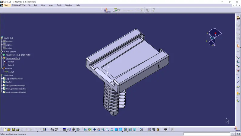
Define the necessary electrical parts, such as the clip and channels.
*Step 3-Adding connectors to the 4 cam-shaft sensors and the 16 fuel injector sensors
Connectors for the cam-shaft and fuel injector sensors are installed in this phase. Thus, the Engine Harness Geometrical Bundle Assembly will require a total of 20 connectors. In order to place each of the 20 connectors where we want them, we must combine manipulation tools with the compass, snap, and smart move functions.
*Step 4- Adding sheet metal bracket.
*Step 5- Installing the wire harness p-clamps and interface connector on the sheet metal bracket.
*Step 6- Mounting of a plastic guiding channel.
*Step 7-Bundle routing to three P-clamps from an interconnection connector.
*Step 8- Bundle routing from Interconnection connector to 3 P-clamps.
*Step 9- Routing to the plastic guiding channel.
*Step 10- Adding branch points to bundle segment inside the guiding channel.
*Step 11- Top shell to harness bundle by adding protective coverings and guiding passages.
*Step 12- Checking bundle continuity.
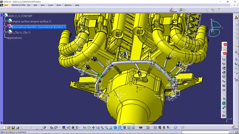
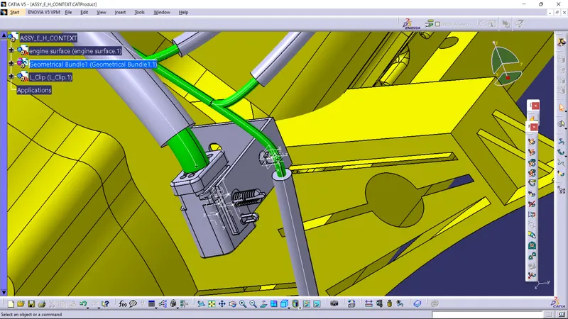
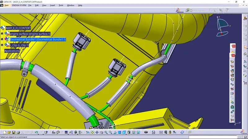
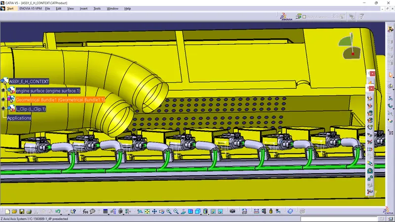
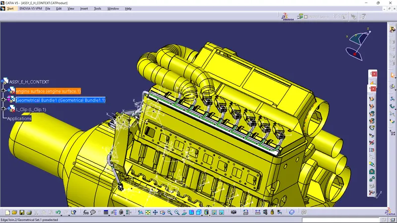
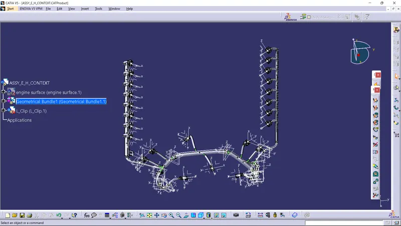
-Making sure multi-branchable is selected before moving on to the next step requires going to Edit>Search>Advanced>Workbench-Electrical>Type-Bundle Segment>Attribute-Fully Connected.
*The 'True' option will display all linked bundle segments, whereas the 'False' option will display all disconnected bundle segments.
*In this case, we chose the 'True' option and ran a search. The fact that every bundle segment is highlighted indicates that they are all electrically connected.