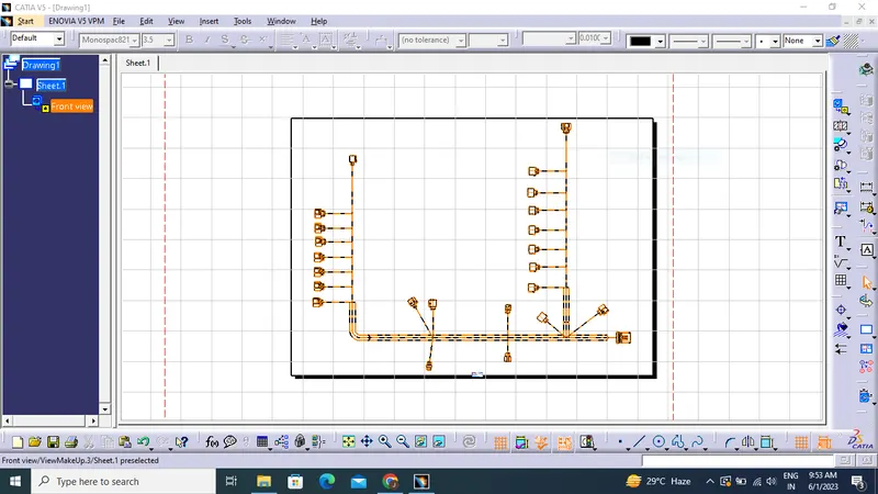
Project 1
PROJECT 1
Route the Wiring harness on Given Engine and Prepare flatten view drawing in CATIA V5. Application of all Packaging rules, Industry best practices studied in this course shall be demonstrated in design. Apply Protection coverings as required.
Prepare & Submit all necessary reports like clearance, Clipping/Clamping selection, Harness fixing requirements, Harness continuity, Assumptions if any along with CATIA 3D data.
DESIGN METHODOLOGY:
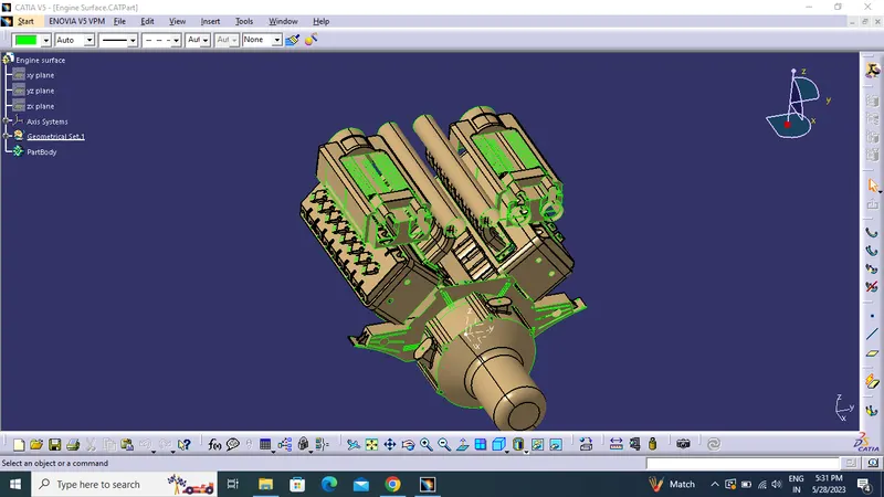
- Download the engine CAD data and required connectors CAD data from the given source.
Using the geometrical parameters created:
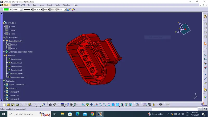
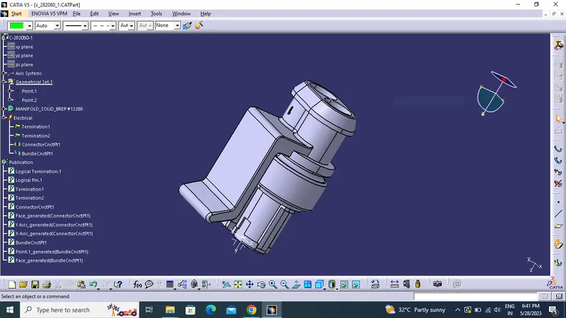
- Define part as electrical connector.
- Define bundle connection point.
- Define connector connection point.
- Define cavity connection point.
C-1563689-1:
C-282080-1:
C-173090-2:
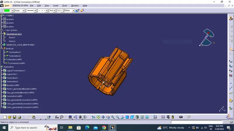
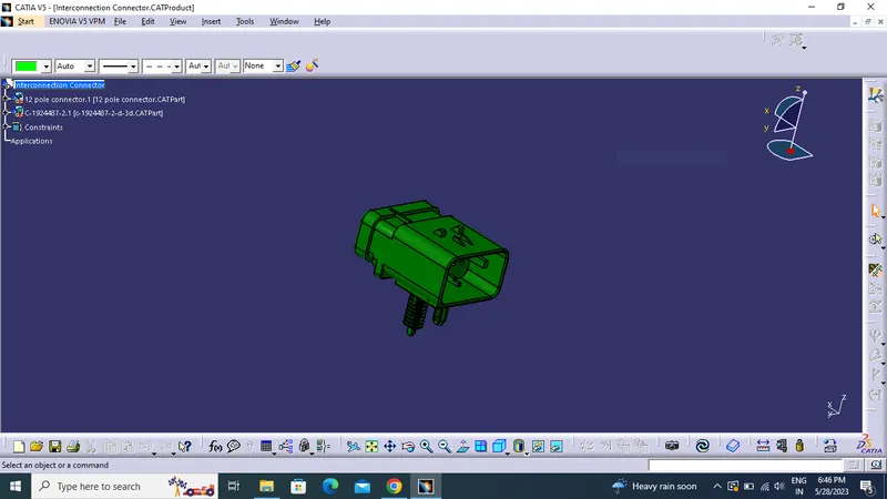
TO CREATE INTERCONNECTION CONNECTOR:
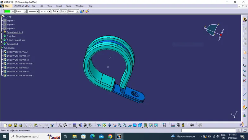
P CLAMP:
CHANNEL:
- Define channel for electrically defining the Channel.
- Create bundle entry point and exit point.
- Create a line curve between the main entry using point on direction .
- Using the geometrical parameters, define the channel electrical using the define mounting equipment option.
- Create define bundle entry points using the define bundle connection point option.
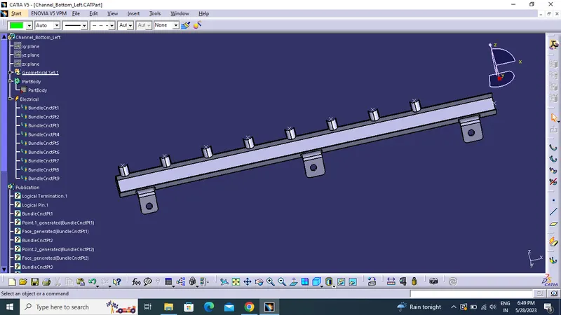
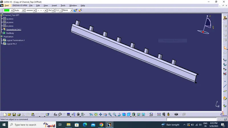
- Same procedure done for the right side channel also.
CREATING ASSEMBLY:
- Create a product file and add the geometrical bundle .
- Define above connector are placed repectively .
- Place the p clamp for guiding bundle.
- Assemble the channel for both right and left side of engine.
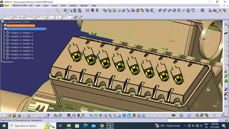
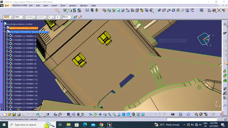
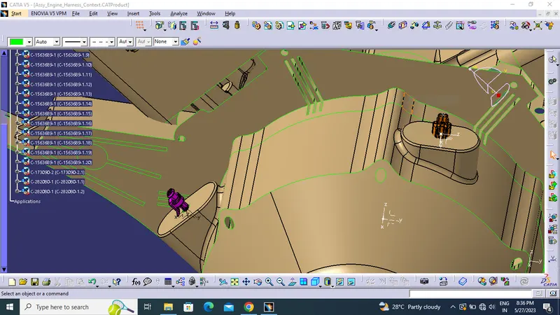
BUNDLE CREATION:
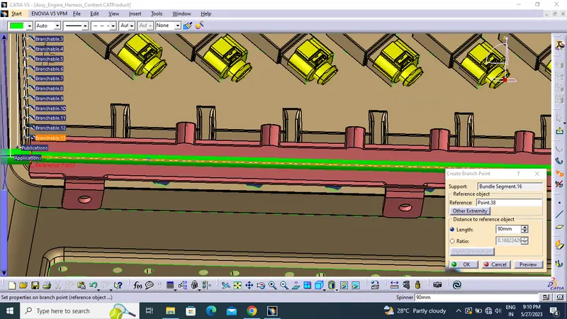
- First, we will locate all the connectors at their desired position, add branch points required.
- Switch electrical harness assembly ,define the product file into electical using geometrical bundle icon.
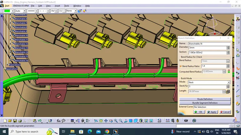
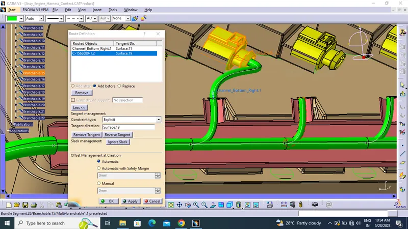
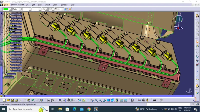
- Then create bundle and sub bundle as a break point.
- Following bundle creation are shown beloe image.
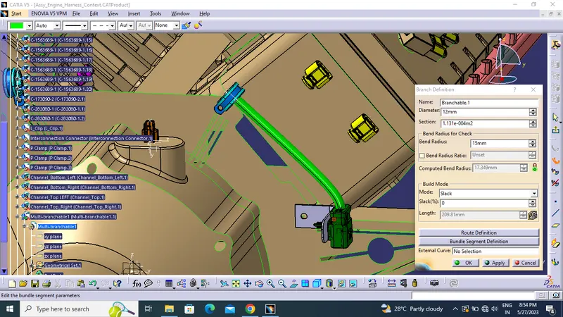
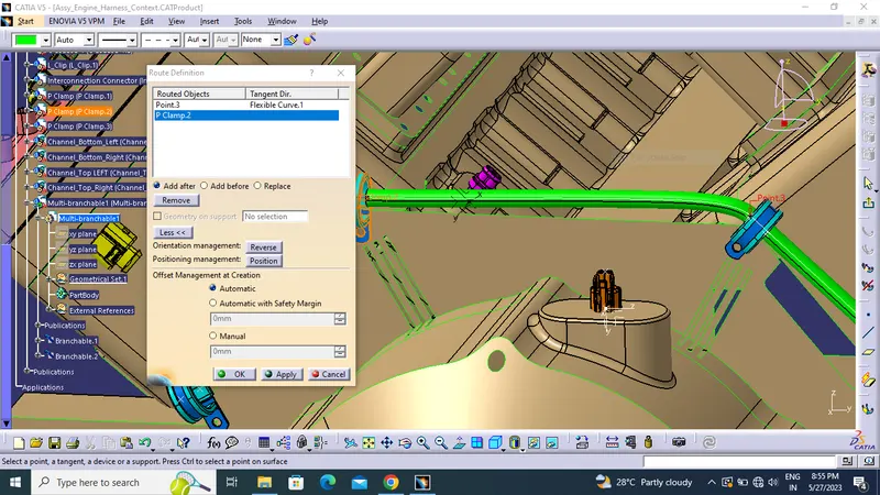
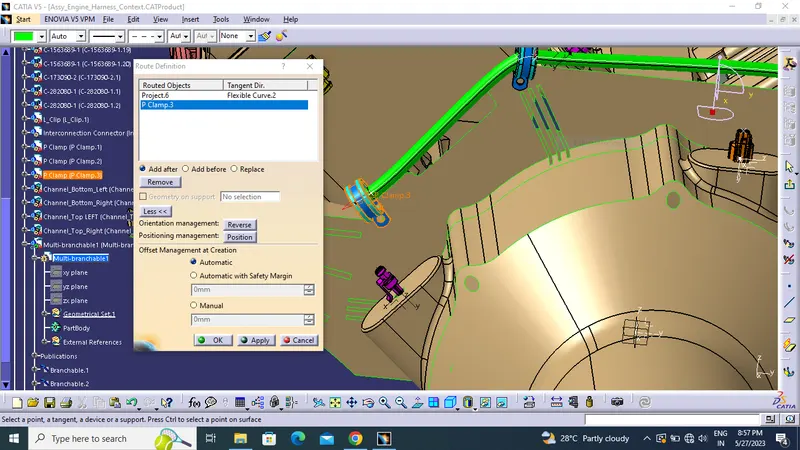
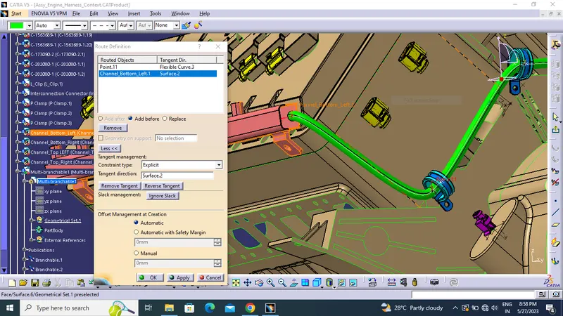
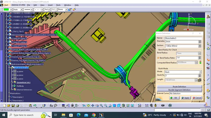
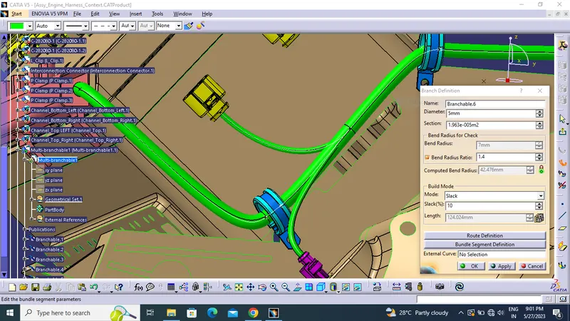
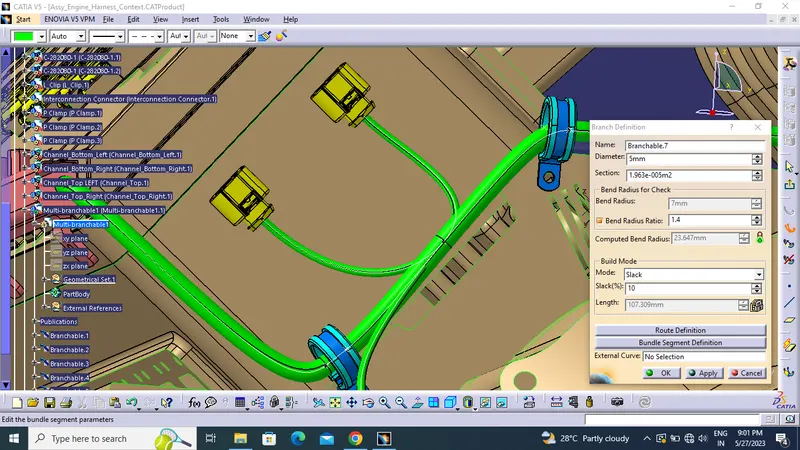
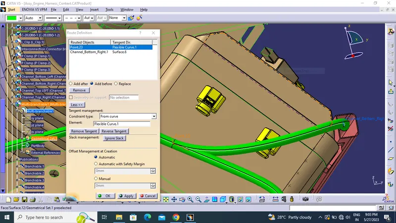
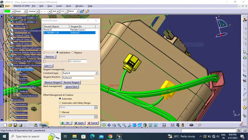
- Create the branch using breaking bundle .
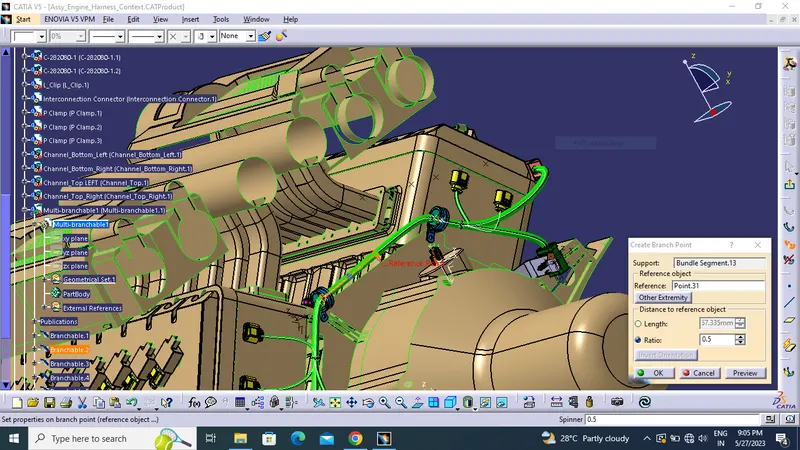
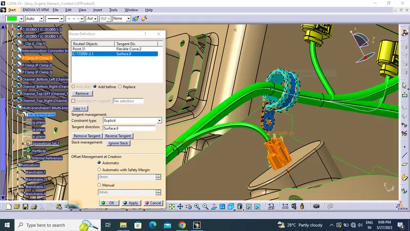
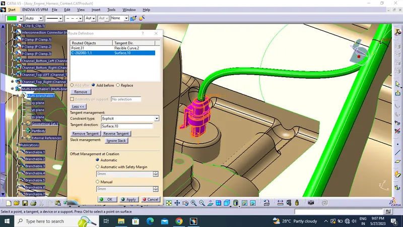
- Create thr bundle in channel using external curve .
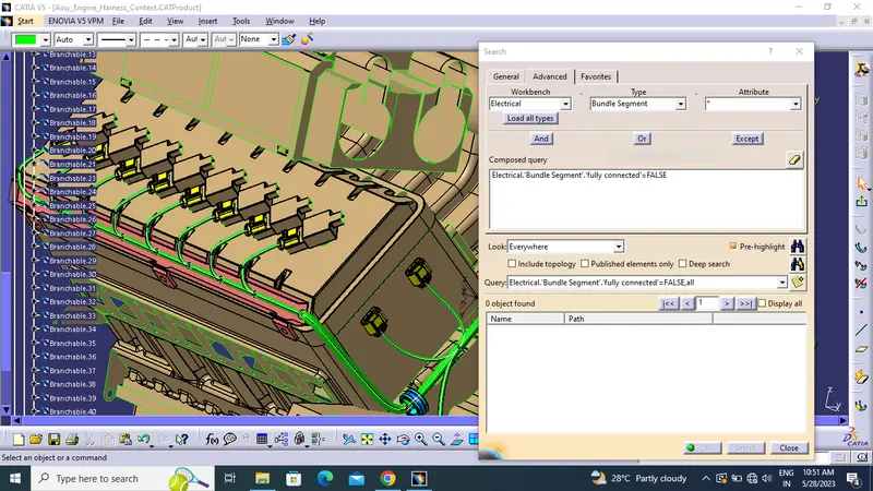
CHECK BUNDLE CONTINUNITY:
- Check bundle continuity .
- Edit>Search>Workbench-Electrical>Type-Bundle segment>Attribute-fully connected.
- In case window appear, that selecting True option will show all the connected bundle segments
- While selecting False option will show all the non-connected bundle segments.
- Now, we will check for True condition and search for result.
- All the bundle segments are showing connected. So there is bundle continuityas shown in below images.
Checking condition as False.
- To check the false coondition
CREATING FLATENING PARAMETER:
- Create the new product file rename it.
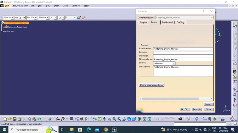
- First we create the new product file and add flatening parameter setting as required.
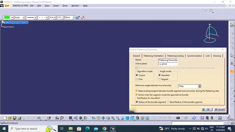
- Drawing setting for drafting.
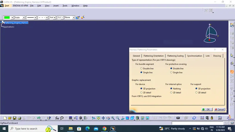
- Bring the harness assembly into the newly created Flattening Product by using the "Extract" feature.
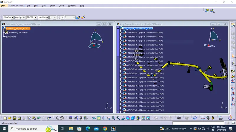
- Using flattening icon create proper assembly.
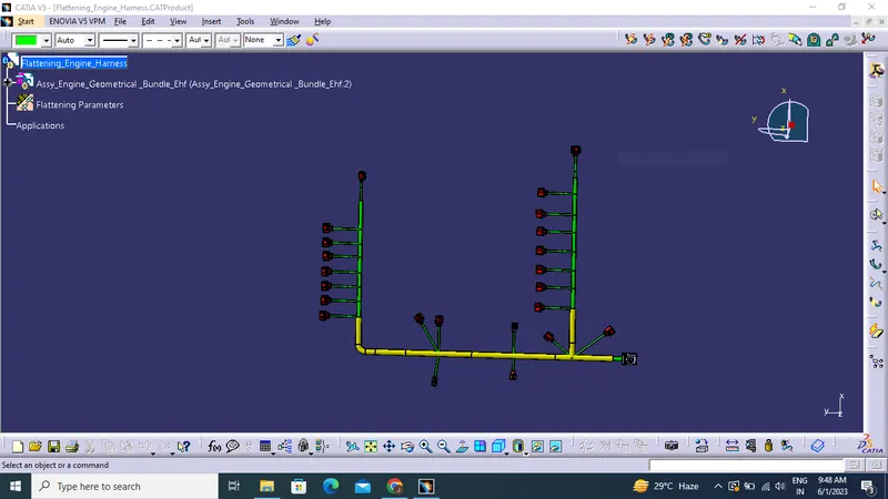
CREATING DRAFTING:
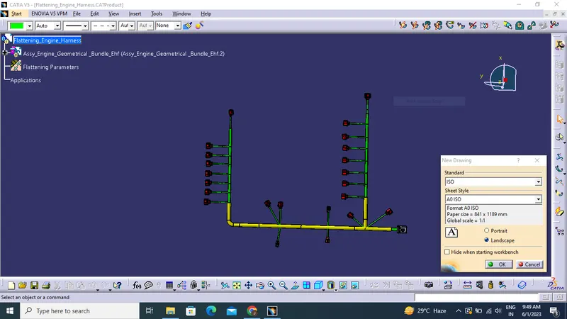
- Creating new drawing file and rename the sheet.
- Click front view icon and select the any face that taken as front view
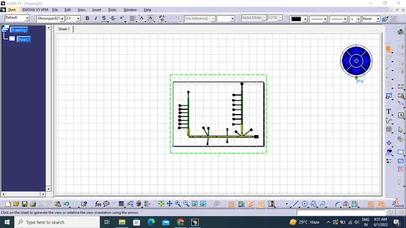
- Define drawing properties.
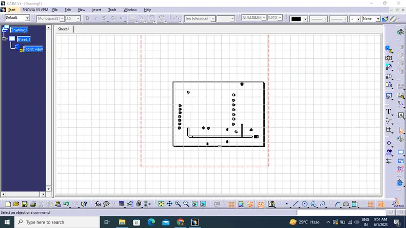
- Click "dress-up" settings 3D wireframe in always "ON". If this setting is not selected the bundle segments will not be visible on the drawing view.
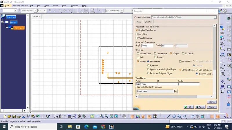
- Final flattened drawing was produced for the wiring harness.