Project 1
1. Design a battery pack for a car roughly 150 Kw with 120 V. Use 3500 mAh 3.6V nominal NMC chemistry cell.
a. Design the battery pack configuration.
Answer :
Given data :
Power(P)=150 Kw
Voltage(V)=120 V
Nominal Current(I)=3.5A
Nominal Voltage(V)=3.6 V
To find the Number of cell in series = Rated Voltage / Nominal Voltage
Number of cell in Series = 120 / 3.6
Number of cell in Series = 33.33 =34
Number of cell in Parallel = Continous Current / Nominal Current
To find the Continous Current = ?
P= VI
I=P/V
I=150/120 = 1.25 A
Number of cell in Parallel = Continous Current / Nominal Current
Number of cell in Parallel = 1.25/3.5
Number of cell in Parallel = 0.35=1
b. Draw the BMS topology for this battery pack.

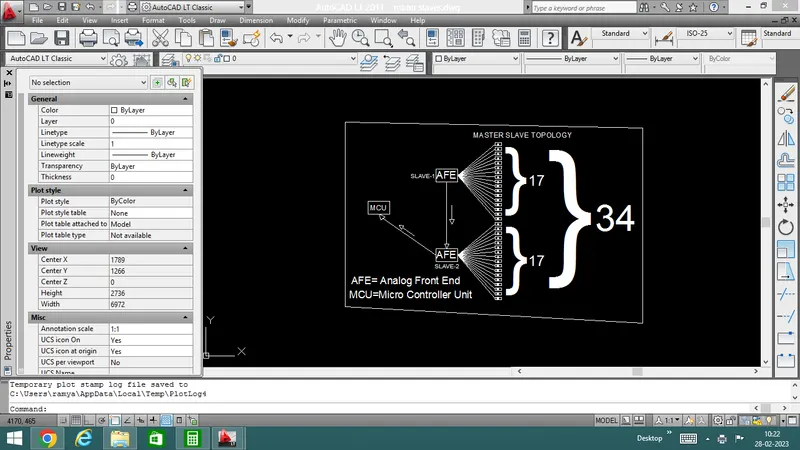
Master Topology : Battery pack which more 18 number cell in series were used in mater slave topology.
Working: when serieslly convert energy storage battery cent to the AFE(slave-1) first connected ES cell data sent to the slave-2 totally connected first and second slaves data trafer to MCU
--------------------------------------------------------------------------------------------------------------
2. Build a 3S2P battery pack configuration with generic battery block using Matlab/Simulink.
Answer : 3S2P Battery Pack Configuration using Simulink Model:
The objective of this article is to connect batteries in 33S2P configuration in Matlab/Simulink. That is 3 cells should be connected in series and 2 cells should be connected in parallel.
Total number of cells in battery pack = No. of cells in series No. of cells in parallel
= 3 X 2 = 6 cells
Step:1 Arrangement of 6 cells
The figure I shows the arrangement of 6 cells. We have to place total number of cells in battery pack (6 cell) in simulink,
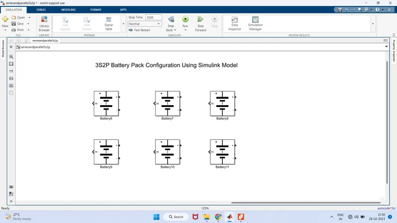
Figure 1: Arrangement of 6 cells
Step: 2 Parallel connection
The figure 2 shows the batteries connected in parallel. For parallel connection, batteries are connected from terminals to same terminals of other batteries that is positive terminal (+) of other battery is connected in positive(+) terminal of the other battery and negative terminal (-) of one battery with negative terminal (-) of the other battery
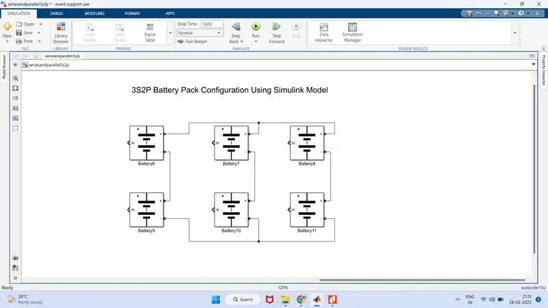
Figure 2: Battery connected in Parallel
Step: 3 Series connection
The figure 3 shows the battery connected in series and parallel combination. Batteries are connected from terminal to terminal in a way that the positive (+) terminal of one battery is connected with the negative (一) terminal of the other battery and negative terminal (-) af one battery is connected with the positive terminal (+) of the other battery.
Figure 3: Battery connected in series and parallel combination
Model Explanation:
The figure 4 shows the 3S2P Battery pack simulink model. The voltage measurement block is connected across the battery pack to measure the battery pack voltage. The scope output used for the battery pack consists of SOC (State of Charge), Current and voltage. The controlled current signal is given as the load to the battery pack. The constant block is determined with battery capacity and it is given to the controlled current block.
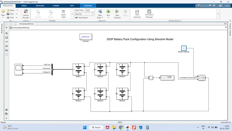
The figure 4 shows the 3S2P Battery pack simulink model.
Parameters given inside the battery is given below
S.no Battery Parameters Value
1. Nominal voltage of the cell 7.2V
2. Rated capacity of a cell 6mAh
3. Maximum voltage of a cell 8.3V
Nominal voltage of the battery pack no of coll in series nominal voltage of a cell
=3 X 7.2v = 21.6V
Rated copocity of the battery packno.of cell in parallel rated capacity of a cell
= 2 X 6 Ah = 12 Ah
The model is for on 21.6V 12Ah battery.
The figure 5 shows the single battery output for SOC, voltage and current
Plot -1 : The SOC (szote of charge) is started to reduce from 100% to 50% corresponding to the load given.
Plot-2 : The current signal is determined by the lood and the decrease in current is due to regenerative braking
Plot-3: The voltage is around 8.4 V The increasing and decreasing voltage in with respect to the regenerative braking.
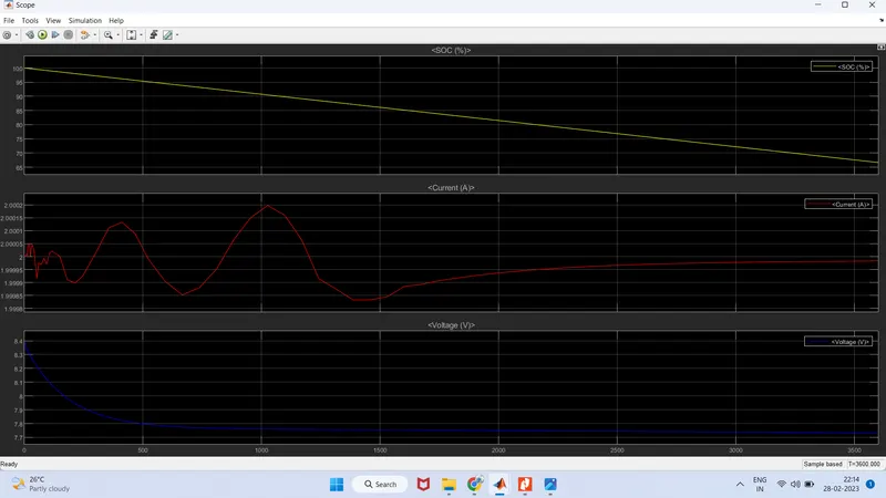
Figure 5: Single battery output for SOC, voltage and current
The figure 6 shows the overall output voltage of the bottery pack. The calculation for the overall output voltage of the battery pack is given below.
Overall voltage of the battery pack maximum voltage of the battery no. of cells in series
= 8.4 x 3 = 25.2 V
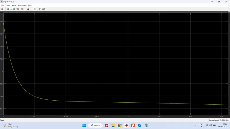
Figure 6: Overall output Voltage of battery pack